US973381A - Vise. - Google Patents
Vise. Download PDFInfo
- Publication number
- US973381A US973381A US50603709A US1909506037A US973381A US 973381 A US973381 A US 973381A US 50603709 A US50603709 A US 50603709A US 1909506037 A US1909506037 A US 1909506037A US 973381 A US973381 A US 973381A
- Authority
- US
- United States
- Prior art keywords
- jaws
- ways
- vise
- base
- cradle
- Prior art date
- Legal status (The legal status is an assumption and is not a legal conclusion. Google has not performed a legal analysis and makes no representation as to the accuracy of the status listed.)
- Expired - Lifetime
Links
Images
Classifications
-
- B—PERFORMING OPERATIONS; TRANSPORTING
- B25—HAND TOOLS; PORTABLE POWER-DRIVEN TOOLS; MANIPULATORS
- B25B—TOOLS OR BENCH DEVICES NOT OTHERWISE PROVIDED FOR, FOR FASTENING, CONNECTING, DISENGAGING, OR HOLDING
- B25B1/00—Vices
- B25B1/06—Arrangements for positively actuating jaws
- B25B1/08—Arrangements for positively actuating jaws using cams
Definitions
- This invention relates to an automatically operating vise intended more especially for use in connection with boring implements, such as drills, but being useful in various applications where a body is to be gripped and held stationary while being operated upon.
- FIG. 1 is a view in side elevation of my improved vise, certain parts of a drill being shown in dotted lines to illustrate the method of use of the device.
- Fig. 2 is a top plan view of the vise on an enlarged scale.
- Fig. 3 is substantially a transverse sectional view taken onv a line at one side of the device, jaws of the vise being shown .in elevation, and certain guide pins being shown in section, and
- Fig. 4 is a sectional view on'the line 4-4 of Fig. 3.
- the device comprises a base 1, having on opposite sides elongated or other apertures 2, by means of which it may be suitably secured on a suitable support, such as the bed 3 of a drill press.
- a suitable support such as the bed 3 of a drill press.
- Each of the side members 4 has in its upper side a large V- shaped recess which extends from opposite ends of each side to the middle of the side member, and thus provides two inclined ways 5 on which the jaws (3 of the vise are adapted to slide.
- Each of the side members 4 is provided near the edge of each of the ways 5 with a lixed stud 7 which projects inward a short distance beyond the inner face of the side members as shown in Fig. 4.
- Each of the jaws 6 is preferably provided with a series of stepped and interdental recesses 8 to accommodate, and form gripping surfaces for, various sizes of objects.
- the jaws rest upon the inclined ways 5, and have a central reduced portion forming a rib 9 which fits snugly, but so as not to bind, in the space between the side members 4.
- Each of these ribs is provided on opposite sides with a longitudinally-disposed groove 10, each of which receives a stud 7 by means of bases 1T of the cradle.
- the said studs preferably having straight parallel sides to better perform the guiding function, as will be understood.
- I indicates a member which I term a cradle, which consists of two semicircular sides 12 united at their upper ends by crosspieces 13.
- the pivot 16 is located centrally of the cradle 11, as respects distance from its ends, and by raising or lowering the lever 14 the cradle 11 may be raised or lowered.
- Each of the sides 12 of the cradle is recessed in its upper portion in a manner to provide a flat base 17 extending parallel with the base 1.
- Each of the jaws f3 is provided at its lower end with a flat surface 18 which normally rests upon the Projecting rearwardly and centrally from each of the jaws 6 is an arm 19, which arms project between the sides 12 of the cradle and are adapted to be engaged on their upper sides by the cross-pieces 13 of the cradle. Then the cradle 11 is elevated by raising-the lever 14 thejaws G will likewise be raised and also caused to diverge.
- the operator may increase the grip ofthe jaws by pressing down on the lever 14, in which operation the cross-pieces 13 will engage the upper sides of the arms 19, and thereby press the jaws more firmly toward each other as will be understood.
- the parts of the vise are of metal.
- base and side members, the cradle, and each of the jaws, are respectively made as integral structures.
- a vise comprising a base, a frameA thereon affording oppositely-disposed inclined ways converging toward said base, and a jaw mounted to slide on each of said ways, said jaws, when raised, being free to slide down said ways under the action of gravity, and being provided with corresponding stepped recesses affording horizontal supporting, and vertical gripping surfaces.
- a vise comprising a base, a frame thereon affording oppositely-inclined ways converging toward said base, a aw mounted to slide on each of said ways, means for simultaneously raising said jaws, the latter, when raised, being free to slide down said ways under the action of gravity.
- a vise comprising a base, a frame thereon affording oppositely-inclined ways converging toward said base, a jaw mounted to slide on each of said ways, said jaws, when raised, being free to slide down said ways under the action of gravity, and means for simultaneously raising or lowering said jaws.
- a vise comprising a base, a frame thereon affording oppositelydnclined ways converging toward said base, a jaw mounted to slide on each of said ways, guides for each of said jaws, said jaws, when raised, being free to slide down said ways under the action of gravity, and means for simultaneously raising said aws.
- a vise comprising a base, a frame thereon affording oppositely-inclined ways, a jaw mounted to slide on each of. said ways, guides for each of said jaws, said aws, when raised, being free to slide down said ways under the action of gravity, and means pivj otally mounted on the vise and associated, but unconnected, with said jaws, for simultaneously raising the same.
- a vise comprising a base having parallel side members extending upward therefrom, each of which is provided on its upper side with oppositely-inclined ways, jaws mounted to slide on said ways, each of said jaws being provided with longitudinallyw disposed grooves, studs in said side members engaging in said grooves, and means for raising said aws.
- a vise comprising a base, a frame thereon affording oppositely-inclined ways, a pair of jaws mounted to slide on said ways, said jaws, when raised, being free to slide down said ways under the action of gravity, guides for said jaws, a cradle supporting said jaws at their lower ends, but independent thereof, and means for raising and lowering said cradle.
- a vise comprising a frame affording oppositely-inclined ways, a pair of self-closing jaws slidably mounted on said ways, guides for said jaws, each of said jaws hav ing on its upper side gripping surfaces and on its under side an outwardly-projecting arm, a cradle mounted to support said aws at their lower end and having its opposite ends extending over said arms, and means for raising and lowering said cradle.
- a vise comprising a frame affording oppositely-inclined ways, jaws mounted to slide on said ways,and having gripping surfaces on their upper sides, guides for said jaws, arms projecting outwardly from the under side of each of said jaws, a lever pivotally mounted at one end in said frame, acradle pivotally mounted on said lever intermediate the ends of the latter, said cradle being adapted to engage the lower ends of said jaws and the upper sides of said arms, whereby when said lever is raised or lowered the jaws may be made to diverge or approach each other respectively.
Landscapes
- Engineering & Computer Science (AREA)
- Mechanical Engineering (AREA)
- Gripping Jigs, Holding Jigs, And Positioning Jigs (AREA)
Description
Patented Oct. 18,1910.
Y .oo/mbf DENNIS PARKS, OF ST. LOUIS, MISSOURI.
VISE.
massi.
Specification of Letters Patent.
Patented Got. 18, 1910.
Application filed July 6, 1909. Serial No. 506,037.
To all whom 'it may concern:
Be it known that I, DENNIS PARKS, a citi- Zen of the United States, residing in the city of St. Louis and State of Missouri, have invent-ed new and useful Improvements in Vises, of which the following is a specification.
This invention relates to an automatically operating vise intended more especially for use in connection with boring implements, such as drills, but being useful in various applications where a body is to be gripped and held stationary while being operated upon.
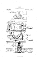
In the accompanying drawing Figure 1 is a view in side elevation of my improved vise, certain parts of a drill being shown in dotted lines to illustrate the method of use of the device. Fig. 2 is a top plan view of the vise on an enlarged scale. Fig. 3 is substantially a transverse sectional view taken onv a line at one side of the device, jaws of the vise being shown .in elevation, and certain guide pins being shown in section, and Fig. 4 is a sectional view on'the line 4-4 of Fig. 3.
The device comprises a base 1, having on opposite sides elongated or other apertures 2, by means of which it may be suitably secured on a suitable support, such as the bed 3 of a drill press. Rising from the base 1, and preferably, though not necessarily, formed integra-l therewith, are two side members 4, which with the base form the frame of the machine. Each of the side members 4 has in its upper side a large V- shaped recess which extends from opposite ends of each side to the middle of the side member, and thus provides two inclined ways 5 on which the jaws (3 of the vise are adapted to slide. Each of the side members 4 is provided near the edge of each of the ways 5 with a lixed stud 7 which projects inward a short distance beyond the inner face of the side members as shown in Fig. 4. Each of the jaws 6 is preferably provided with a series of stepped and interdental recesses 8 to accommodate, and form gripping surfaces for, various sizes of objects. The jaws rest upon the inclined ways 5, and have a central reduced portion forming a rib 9 which fits snugly, but so as not to bind, in the space between the side members 4. Each of these ribs is provided on opposite sides with a longitudinally-disposed groove 10, each of which receives a stud 7 by means of bases 1T of the cradle.
edected by the force of gravity.
which the jaws are guided to move in right lines, the said studs preferably having straight parallel sides to better perform the guiding function, as will be understood.
11 indicates a member which I term a cradle, which consists of two semicircular sides 12 united at their upper ends by crosspieces 13.
14 indicates a lever which is pivoted at its inner end, as indicated at 15, between the side members 4, and intermediate its ends between the sides 12 of the cradle 11, indicated at 1G. The pivot 16 is located centrally of the cradle 11, as respects distance from its ends, and by raising or lowering the lever 14 the cradle 11 may be raised or lowered. Each of the sides 12 of the cradle is recessed in its upper portion in a manner to provide a flat base 17 extending parallel with the base 1. Each of the jaws f3 is provided at its lower end with a flat surface 18 which normally rests upon the Projecting rearwardly and centrally from each of the jaws 6 is an arm 19, which arms project between the sides 12 of the cradle and are adapted to be engaged on their upper sides by the cross-pieces 13 of the cradle. Then the cradle 11 is elevated by raising-the lever 14 thejaws G will likewise be raised and also caused to diverge. As soon as the lever 14 is released the will tend to slide down the ways 5 and consequently to approach each other, this action being automatic and A body, such as indicated in dotted lines by 20, having been placed between the `jaws at a proper height thereon, according to its size, when 'the lever 14 is released the jaws will aut-omatically grip the object and the harder the object is pressed upon, as in being bored by a drill 21, the firmer the jaws will grip the body. If, however, from the nature or shape of the body to be gripped by the vise, or from lack of pressure upon the body, as when the drill 21 has passed through it, or when the drill is being withdrawn, the jaws do not grip the body with sufficient firmness to hold it from turning or other movement, the operator may increase the grip ofthe jaws by pressing down on the lever 14, in which operation the cross-pieces 13 will engage the upper sides of the arms 19, and thereby press the jaws more firmly toward each other as will be understood.
The parts of the vise are of metal. The
base and side members, the cradle, and each of the jaws, are respectively made as integral structures.
I claim:
l. A vise comprising a base, a frameA thereon affording oppositely-disposed inclined ways converging toward said base, and a jaw mounted to slide on each of said ways, said jaws, when raised, being free to slide down said ways under the action of gravity, and being provided with corresponding stepped recesses affording horizontal supporting, and vertical gripping surfaces.
2. A vise comprising a base, a frame thereon affording oppositely-inclined ways converging toward said base, a aw mounted to slide on each of said ways, means for simultaneously raising said jaws, the latter, when raised, being free to slide down said ways under the action of gravity.
3. A vise comprising a base, a frame thereon affording oppositely-inclined ways converging toward said base, a jaw mounted to slide on each of said ways, said jaws, when raised, being free to slide down said ways under the action of gravity, and means for simultaneously raising or lowering said jaws.
l. A vise comprising a base, a frame thereon affording oppositelydnclined ways converging toward said base, a jaw mounted to slide on each of said ways, guides for each of said jaws, said jaws, when raised, being free to slide down said ways under the action of gravity, and means for simultaneously raising said aws.
5. A vise comprising a base, a frame thereon affording oppositely-inclined ways, a jaw mounted to slide on each of. said ways, guides for each of said jaws, said aws, when raised, being free to slide down said ways under the action of gravity, and means pivj otally mounted on the vise and associated, but unconnected, with said jaws, for simultaneously raising the same.
G. A vise comprising a base having parallel side members extending upward therefrom, each of which is provided on its upper side with oppositely-inclined ways, jaws mounted to slide on said ways, each of said jaws being provided with longitudinallyw disposed grooves, studs in said side members engaging in said grooves, and means for raising said aws.
'7. A vise comprising a base, a frame thereon affording oppositely-inclined ways, a pair of jaws mounted to slide on said ways, said jaws, when raised, being free to slide down said ways under the action of gravity, guides for said jaws, a cradle supporting said jaws at their lower ends, but independent thereof, and means for raising and lowering said cradle.
S. A vise comprising a frame affording oppositely-inclined ways, a pair of self-closing jaws slidably mounted on said ways, guides for said jaws, each of said jaws hav ing on its upper side gripping surfaces and on its under side an outwardly-projecting arm, a cradle mounted to support said aws at their lower end and having its opposite ends extending over said arms, and means for raising and lowering said cradle.
9. A vise comprising a frame affording oppositely-inclined ways, jaws mounted to slide on said ways,and having gripping surfaces on their upper sides, guides for said jaws, arms projecting outwardly from the under side of each of said jaws, a lever pivotally mounted at one end in said frame, acradle pivotally mounted on said lever intermediate the ends of the latter, said cradle being adapted to engage the lower ends of said jaws and the upper sides of said arms, whereby when said lever is raised or lowered the jaws may be made to diverge or approach each other respectively.
In testimony whereof I have hereunto set my hand in presence of two subscribing witnesses.
DENNIS PARKS.
lVitnesses BRUCE S. ELLIOTT, STELLA HILL.
Priority Applications (1)
| Application Number | Priority Date | Filing Date | Title |
|---|---|---|---|
| US50603709A US973381A (en) | 1909-07-06 | 1909-07-06 | Vise. |
Applications Claiming Priority (1)
| Application Number | Priority Date | Filing Date | Title |
|---|---|---|---|
| US50603709A US973381A (en) | 1909-07-06 | 1909-07-06 | Vise. |
Publications (1)
| Publication Number | Publication Date |
|---|---|
| US973381A true US973381A (en) | 1910-10-18 |
Family
ID=3041760
Family Applications (1)
| Application Number | Title | Priority Date | Filing Date |
|---|---|---|---|
| US50603709A Expired - Lifetime US973381A (en) | 1909-07-06 | 1909-07-06 | Vise. |
Country Status (1)
| Country | Link |
|---|---|
| US (1) | US973381A (en) |
-
1909
- 1909-07-06 US US50603709A patent/US973381A/en not_active Expired - Lifetime
Similar Documents
| Publication | Publication Date | Title |
|---|---|---|
| US1050919A (en) | Vise. | |
| US557453A (en) | thompson | |
| US1541715A (en) | Vise | |
| US999979A (en) | Vise. | |
| US762070A (en) | Vise. | |
| US999978A (en) | Vise. | |
| US1070049A (en) | Vise. | |
| US638378A (en) | Tongs. | |
| US690438A (en) | Wire-grip. | |
| US816917A (en) | Cornice-brake. | |
| US348818A (en) | Pipe and rod vise | |
| US1150397A (en) | Vise. | |
| US1385268A (en) | Anvil-vise | |
| US895404A (en) | Device for applying and removing cotter-pins. | |
| US771097A (en) | Vise. | |
| US1756851A (en) | Woodworker's tool | |
| US1043070A (en) | Lifting-jack. | |
| US1320230A (en) | Wrench | |
| US923323A (en) | Bench clamp or vise. | |
| US984638A (en) | Tie-spacer. | |
| US1080338A (en) | Machine for upsetting vehicle-axles. | |
| US928275A (en) | Tool for holding disks for drilling. | |
| US685057A (en) | Work-holder. | |
| US875786A (en) | Bench-dog. | |
| US1412821A (en) | Wrench |