US9731597B2 - Disconnectable driveline with brake system - Google Patents
Disconnectable driveline with brake system Download PDFInfo
- Publication number
- US9731597B2 US9731597B2 US14/967,406 US201514967406A US9731597B2 US 9731597 B2 US9731597 B2 US 9731597B2 US 201514967406 A US201514967406 A US 201514967406A US 9731597 B2 US9731597 B2 US 9731597B2
- Authority
- US
- United States
- Prior art keywords
- gear
- coupling portion
- vehicle
- coupling
- coupled
- Prior art date
- Legal status (The legal status is an assumption and is not a legal conclusion. Google has not performed a legal analysis and makes no representation as to the accuracy of the status listed.)
- Active, expires
Links
Images


Classifications
-
- B—PERFORMING OPERATIONS; TRANSPORTING
- B60—VEHICLES IN GENERAL
- B60K—ARRANGEMENT OR MOUNTING OF PROPULSION UNITS OR OF TRANSMISSIONS IN VEHICLES; ARRANGEMENT OR MOUNTING OF PLURAL DIVERSE PRIME-MOVERS IN VEHICLES; AUXILIARY DRIVES FOR VEHICLES; INSTRUMENTATION OR DASHBOARDS FOR VEHICLES; ARRANGEMENTS IN CONNECTION WITH COOLING, AIR INTAKE, GAS EXHAUST OR FUEL SUPPLY OF PROPULSION UNITS IN VEHICLES
- B60K17/00—Arrangement or mounting of transmissions in vehicles
- B60K17/04—Arrangement or mounting of transmissions in vehicles characterised by arrangement, location, or kind of gearing
- B60K17/16—Arrangement or mounting of transmissions in vehicles characterised by arrangement, location, or kind of gearing of differential gearing
- B60K17/165—Arrangement or mounting of transmissions in vehicles characterised by arrangement, location, or kind of gearing of differential gearing provided between independent half axles
-
- B—PERFORMING OPERATIONS; TRANSPORTING
- B60—VEHICLES IN GENERAL
- B60K—ARRANGEMENT OR MOUNTING OF PROPULSION UNITS OR OF TRANSMISSIONS IN VEHICLES; ARRANGEMENT OR MOUNTING OF PLURAL DIVERSE PRIME-MOVERS IN VEHICLES; AUXILIARY DRIVES FOR VEHICLES; INSTRUMENTATION OR DASHBOARDS FOR VEHICLES; ARRANGEMENTS IN CONNECTION WITH COOLING, AIR INTAKE, GAS EXHAUST OR FUEL SUPPLY OF PROPULSION UNITS IN VEHICLES
- B60K17/00—Arrangement or mounting of transmissions in vehicles
- B60K17/04—Arrangement or mounting of transmissions in vehicles characterised by arrangement, location, or kind of gearing
- B60K17/16—Arrangement or mounting of transmissions in vehicles characterised by arrangement, location, or kind of gearing of differential gearing
-
- B—PERFORMING OPERATIONS; TRANSPORTING
- B60—VEHICLES IN GENERAL
- B60K—ARRANGEMENT OR MOUNTING OF PROPULSION UNITS OR OF TRANSMISSIONS IN VEHICLES; ARRANGEMENT OR MOUNTING OF PLURAL DIVERSE PRIME-MOVERS IN VEHICLES; AUXILIARY DRIVES FOR VEHICLES; INSTRUMENTATION OR DASHBOARDS FOR VEHICLES; ARRANGEMENTS IN CONNECTION WITH COOLING, AIR INTAKE, GAS EXHAUST OR FUEL SUPPLY OF PROPULSION UNITS IN VEHICLES
- B60K17/00—Arrangement or mounting of transmissions in vehicles
- B60K17/28—Arrangement or mounting of transmissions in vehicles characterised by arrangement, location, or type of power take-off
-
- B—PERFORMING OPERATIONS; TRANSPORTING
- B60—VEHICLES IN GENERAL
- B60K—ARRANGEMENT OR MOUNTING OF PROPULSION UNITS OR OF TRANSMISSIONS IN VEHICLES; ARRANGEMENT OR MOUNTING OF PLURAL DIVERSE PRIME-MOVERS IN VEHICLES; AUXILIARY DRIVES FOR VEHICLES; INSTRUMENTATION OR DASHBOARDS FOR VEHICLES; ARRANGEMENTS IN CONNECTION WITH COOLING, AIR INTAKE, GAS EXHAUST OR FUEL SUPPLY OF PROPULSION UNITS IN VEHICLES
- B60K17/00—Arrangement or mounting of transmissions in vehicles
- B60K17/34—Arrangement or mounting of transmissions in vehicles for driving both front and rear wheels, e.g. four wheel drive vehicles
- B60K17/344—Arrangement or mounting of transmissions in vehicles for driving both front and rear wheels, e.g. four wheel drive vehicles having a transfer gear
-
- B—PERFORMING OPERATIONS; TRANSPORTING
- B60—VEHICLES IN GENERAL
- B60K—ARRANGEMENT OR MOUNTING OF PROPULSION UNITS OR OF TRANSMISSIONS IN VEHICLES; ARRANGEMENT OR MOUNTING OF PLURAL DIVERSE PRIME-MOVERS IN VEHICLES; AUXILIARY DRIVES FOR VEHICLES; INSTRUMENTATION OR DASHBOARDS FOR VEHICLES; ARRANGEMENTS IN CONNECTION WITH COOLING, AIR INTAKE, GAS EXHAUST OR FUEL SUPPLY OF PROPULSION UNITS IN VEHICLES
- B60K17/00—Arrangement or mounting of transmissions in vehicles
- B60K17/34—Arrangement or mounting of transmissions in vehicles for driving both front and rear wheels, e.g. four wheel drive vehicles
- B60K17/348—Arrangement or mounting of transmissions in vehicles for driving both front and rear wheels, e.g. four wheel drive vehicles having differential means for driving one set of wheels, e.g. the front, at one speed and the other set, e.g. the rear, at a different speed
- B60K17/35—Arrangement or mounting of transmissions in vehicles for driving both front and rear wheels, e.g. four wheel drive vehicles having differential means for driving one set of wheels, e.g. the front, at one speed and the other set, e.g. the rear, at a different speed including arrangements for suppressing or influencing the power transfer, e.g. viscous clutches
-
- B—PERFORMING OPERATIONS; TRANSPORTING
- B60—VEHICLES IN GENERAL
- B60K—ARRANGEMENT OR MOUNTING OF PROPULSION UNITS OR OF TRANSMISSIONS IN VEHICLES; ARRANGEMENT OR MOUNTING OF PLURAL DIVERSE PRIME-MOVERS IN VEHICLES; AUXILIARY DRIVES FOR VEHICLES; INSTRUMENTATION OR DASHBOARDS FOR VEHICLES; ARRANGEMENTS IN CONNECTION WITH COOLING, AIR INTAKE, GAS EXHAUST OR FUEL SUPPLY OF PROPULSION UNITS IN VEHICLES
- B60K17/00—Arrangement or mounting of transmissions in vehicles
- B60K17/34—Arrangement or mounting of transmissions in vehicles for driving both front and rear wheels, e.g. four wheel drive vehicles
- B60K17/354—Arrangement or mounting of transmissions in vehicles for driving both front and rear wheels, e.g. four wheel drive vehicles having separate mechanical assemblies for transmitting drive to the front or to the rear wheels or set of wheels
-
- B—PERFORMING OPERATIONS; TRANSPORTING
- B60—VEHICLES IN GENERAL
- B60K—ARRANGEMENT OR MOUNTING OF PROPULSION UNITS OR OF TRANSMISSIONS IN VEHICLES; ARRANGEMENT OR MOUNTING OF PLURAL DIVERSE PRIME-MOVERS IN VEHICLES; AUXILIARY DRIVES FOR VEHICLES; INSTRUMENTATION OR DASHBOARDS FOR VEHICLES; ARRANGEMENTS IN CONNECTION WITH COOLING, AIR INTAKE, GAS EXHAUST OR FUEL SUPPLY OF PROPULSION UNITS IN VEHICLES
- B60K23/00—Arrangement or mounting of control devices for vehicle transmissions, or parts thereof, not otherwise provided for
- B60K23/08—Arrangement or mounting of control devices for vehicle transmissions, or parts thereof, not otherwise provided for for changing number of driven wheels, for switching from driving one axle to driving two or more axles
- B60K23/0808—Arrangement or mounting of control devices for vehicle transmissions, or parts thereof, not otherwise provided for for changing number of driven wheels, for switching from driving one axle to driving two or more axles for varying torque distribution between driven axles, e.g. by transfer clutch
-
- F—MECHANICAL ENGINEERING; LIGHTING; HEATING; WEAPONS; BLASTING
- F16—ENGINEERING ELEMENTS AND UNITS; GENERAL MEASURES FOR PRODUCING AND MAINTAINING EFFECTIVE FUNCTIONING OF MACHINES OR INSTALLATIONS; THERMAL INSULATION IN GENERAL
- F16H—GEARING
- F16H37/00—Combinations of mechanical gearings, not provided for in groups F16H1/00 - F16H35/00
- F16H37/02—Combinations of mechanical gearings, not provided for in groups F16H1/00 - F16H35/00 comprising essentially only toothed or friction gearings
- F16H37/06—Combinations of mechanical gearings, not provided for in groups F16H1/00 - F16H35/00 comprising essentially only toothed or friction gearings with a plurality of driving or driven shafts; with arrangements for dividing torque between two or more intermediate shafts
- F16H37/08—Combinations of mechanical gearings, not provided for in groups F16H1/00 - F16H35/00 comprising essentially only toothed or friction gearings with a plurality of driving or driven shafts; with arrangements for dividing torque between two or more intermediate shafts with differential gearing
- F16H37/0806—Combinations of mechanical gearings, not provided for in groups F16H1/00 - F16H35/00 comprising essentially only toothed or friction gearings with a plurality of driving or driven shafts; with arrangements for dividing torque between two or more intermediate shafts with differential gearing with a plurality of driving or driven shafts
- F16H37/0813—Combinations of mechanical gearings, not provided for in groups F16H1/00 - F16H35/00 comprising essentially only toothed or friction gearings with a plurality of driving or driven shafts; with arrangements for dividing torque between two or more intermediate shafts with differential gearing with a plurality of driving or driven shafts with only one input shaft
-
- B—PERFORMING OPERATIONS; TRANSPORTING
- B60—VEHICLES IN GENERAL
- B60Y—INDEXING SCHEME RELATING TO ASPECTS CROSS-CUTTING VEHICLE TECHNOLOGY
- B60Y2400/00—Special features of vehicle units
- B60Y2400/42—Clutches or brakes
- B60Y2400/421—Dog type clutches or brakes
-
- B—PERFORMING OPERATIONS; TRANSPORTING
- B60—VEHICLES IN GENERAL
- B60Y—INDEXING SCHEME RELATING TO ASPECTS CROSS-CUTTING VEHICLE TECHNOLOGY
- B60Y2400/00—Special features of vehicle units
- B60Y2400/42—Clutches or brakes
- B60Y2400/424—Friction clutches
-
- B—PERFORMING OPERATIONS; TRANSPORTING
- B60—VEHICLES IN GENERAL
- B60Y—INDEXING SCHEME RELATING TO ASPECTS CROSS-CUTTING VEHICLE TECHNOLOGY
- B60Y2410/00—Constructional features of vehicle sub-units
- B60Y2410/10—Housings
Definitions
- the present disclosure relates to a disconnectable driveline having a brake system.
- AWD all-wheel drive
- FWD front-wheel drive
- This optional drivetrain arrangement permits drive torque to be selectively and/or automatically transferred from the powertrain to both the primary (i.e., front) driveline and the secondary (i.e., rear) driveline to provide better traction when the vehicle is operated in inclement weather and on off-highway road conditions.
- AWD vehicles necessarily are equipped with a much more complex drivetrain which, in addition to the primary driveline, must include the additional components associated with the secondary driveline such as a power take-off unit and a propshaft.
- the present teachings provide a vehicle driveline that includes a housing, an input shaft mounted in the housing for rotation about a first axis, a differential case coupled to the input shaft for rotation about the first axis, a differential gearset received in the differential case, a first gear received in the housing and rotatable about the first axis, a coupling, a brake element and an output shaft.
- the coupling has a first coupling portion, which is coupled to the input shaft for rotation therewith, and a second coupling portion that is axially slidably but non-rotatably coupled to the first gear.
- the second coupling portion is movable along the first axis between a first coupling position, in which rotary power is transmittable between the input shaft and the first gear, and a second coupling position in which rotary power is not transmittable between the input shaft and the first gear.
- the brake element is coupled to the housing and is engagable to the second coupling portion when the second coupling portion is in the second coupling position to resist rotation of the second coupling portion relative to the housing.
- the output shaft is drivingly coupled to the first gear and is rotatable about a second axis that is not parallel to the first axis.
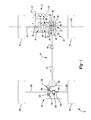
- FIG. 1 is a schematic illustration of an exemplary vehicle constructed in accordance with the teachings of the present disclosure.
- FIG. 2 is a section view of a portion of the vehicle of FIG. 1 illustrating a portion of a power take-off unit in more detail.
- an exemplary vehicle constructed in accordance with the teachings of the present disclosure is generally indicated by reference numeral 10 .
- the vehicle 10 can have a power train 12 and a drive train or driveline 14 .
- the power train 12 can be conventionally constructed and can comprise a power source 16 and a transmission 18 .
- the power source 16 can be configured to provide propulsive power and can comprise an internal combustion engine and/or an electric motor, for example.
- the transmission 18 can receive propulsive power from the power source 16 and can output power to the driveline 14 .
- the transmission 18 can have a plurality of automatically or manually-selected gear ratios.
- the driveline 14 can include a front axle assembly 20 , a power take-off unit (PTU) 22 , a propshaft 24 and a rear axle assembly 26 .
- An output of the transmission 18 can be drivingly coupled to an input 30 of the front axle assembly 20 .
- the front axle assembly 20 can include a front or first differential assembly 34 that can include a front or first differential case 36 and a front or first differential gearset 38 .
- the first differential case 36 is rotatable about a first rotary axis 40 .
- the first differential assembly 34 is configured to distribute rotary power from the first differential case 36 to a pair of front or first axle shafts 42 on a full-time basis to drive an associated pair of front or first wheels 44 .
- the PTU 22 can comprise a housing 50 , an input shaft 52 , a first gear 54 , a coupling 56 , a brake element 58 and an output shaft 60 .
- the housing 50 can be configured to house the other components of the PTU 22 and optionally can be configured to house all or a portion of the front axle assembly 20 . Accordingly, it will be appreciated that the housing 50 can comprise a plurality of discrete housing components (not specifically shown) that can be assembled together to form the housing 50 .
- the input shaft 52 can be fixedly coupled to the first differential case 36 for common rotation about the first rotary axis 40 .
- the first gear 54 can be rotatable about the first rotary axis 40 .
- the first gear 54 is a type of bevel gear, such as a straight bevel gear, a spiral bevel gear or a hypoid gear, and is configured to cooperate with another gear (i.e., a pinion gear 64 that is fixedly coupled to the output shaft 60 ) to direct rotary power along a generally perpendicular power transmission path.
- the first gear 54 could be a spur or helical gear (not shown) that is configured to transmit rotary power along a transmission path that employs one or more pairs of gears having parallel rotational axes.
- An example of this latter type of PTU is shown in commonly assigned U.S. Pat. No.
- the first gear 54 is mounted on a hollow spool 66 that is supported for rotation relative to the housing 50 by a pair of bearings 68 ( FIG. 2 ), which can comprise one or more angular ball bearings and/or one or more tapered roller bearings and/or a four-point angular contact bearing.
- bearings 68 FIG. 2
- One of the first axle shafts 42 can be received through the spool 66 and the first gear 54 .
- the coupling 56 can be any type of device that can be employed to selectively transmit rotary power between the input shaft 52 and the first gear 54 , such as a friction clutch (not shown) or a toothed collar (not shown) that can be slid axially along the first rotary axis 40 to selectively engage a toothed member (not shown) that is coupled for rotation with the input shaft 52 .
- a friction clutch (not shown) or a toothed collar (not shown) that can be slid axially along the first rotary axis 40 to selectively engage a toothed member (not shown) that is coupled for rotation with the input shaft 52 .
- the coupling 56 in the particular example provided is a claw or dog clutch.
- the coupling 56 can generically include a first coupling portion 70 (e.g., a first clutch dog), which can be coupled to the input shaft 52 for common rotation, and a second coupling portion 72 (e.g., a second clutch dog) that can be non-rotatably coupled to the first gear 54 for common rotation but axially slidable along the first rotary axis 40 relative to the first gear 54 .
- a cantilevered portion 66 a of the spool 66 extends along the first axis from the first gear 54 in a direction toward the first coupling portion 70 and includes a plurality of male or external spline teeth 76 that are engaged by a plurality of female or internal splined teeth 78 formed in the second coupling portion 72 .
- any type of actuator can be employed to translate the second coupling portion 72 between a first coupling position, in which the second coupling portion 72 is drivingly coupled to the first coupling portion 70 to permit the transmission of rotary power between the input shaft 52 and the first gear 54 , and a second coupling position in which the second coupling portion 72 is disengaged from the first coupling portion 70 to thereby inhibit the transmission of rotary power between the input shaft 52 and the first gear 54 .
- the second coupling portion 72 defines a clutch fork groove 80 that is configured to receive a conventional clutch fork 82 ( FIG. 1 ) that can be translated by any appropriate mechanism, such as a linear motor 84 ( FIG. 1 ).
- the brake element 58 can be non-rotatably coupled to the housing 50 and engagable to the second coupling portion 72 when the second coupling portion 72 is decoupled from the first coupling portion 70 and moved toward the second coupling position.
- the brake element 58 is mounted to the housing 50 for sliding movement along the first rotary axis 40 and is biased by a spring 90 in a direction along the first rotary axis 40 toward the second coupling portion 72 .
- first stop element 84 which could be integrally formed with the housing 50
- the brake element 58 can limit movement of the brake element 58 in the direction along the first rotary axis 40 toward the second coupling portion 72 so that the brake element 58 cannot engage the second coupling portion 72 when the second coupling portion 72 is in the first coupling position.
- Contact between a second stop element 86 which can comprise a snap ring that is received into a groove 88 in the housing 50 , can restrain an end of the spring 90 on a side opposite the brake element 58 .
- the second coupling portion 72 can include a first friction surface 100 that can engage a second friction surface 102 formed on the brake element 58 when the brake element 58 and the second coupling portion 72 are engaged to one another.
- the first and second friction surfaces 100 and 102 have a frusto-conical shape, but it will be appreciated that the first and second friction surfaces 100 and 102 can be shaped differently.
- the first friction surface 100 and/or the second friction surface 102 can be configured with a desired set of tribological properties to control friction, lubrication and wear between the first and second friction surfaces 100 and 102 when the brake element 58 and the second coupling portion 72 are engaged to one another.
- the material from which the first friction surface 100 and/or second friction surface 102 is formed (including base materials and any subsequent coatings), the heat treatment and surface finish of the first and second friction surfaces 100 and 102 , and/or the use of a friction material or layer with one or both of the first and second friction surfaces 100 and 102 can be employed to provide a desired level of friction, wear resistance and lubrication control.
- the output shaft 60 is rotatable about a second rotary axis (coincident with the output shaft 60 that is schematically shown in FIG. 1 ) that can be generally perpendicular to the first rotary axis 40 .
- the output shaft 60 can be drivingly coupled to a first end of the propshaft 24 .
- the propshaft 24 is configured to transmit rotary power between the output shaft 60 of the PTU 22 and an input pinion 120 associated with the rear axle assembly 26 .
- the rear axle assembly 26 can further include a ring gear 122 , a rear or second differential assembly 124 , a pair of rear or second axle shafts 126 , and a disconnect system 128 .
- the ring gear 122 can be meshingly engaged with the input pinion 120 .
- the second differential assembly 124 can include a second differential case 130 and a pair of differential output members 138 . Each of the differential output members 138 is configured to drive an associated one of the second axle shafts 126 .
- the disconnect system 128 can comprise one or more couplings that is selectively operable to inhibit the transmission of vehicle propulsive power from the propshaft 24 to at least one of the second axle shafts 126 .
- the disconnect system 128 comprises a friction clutch 134 that is employed to selectively couple the ring gear 122 to the second differential case 130 , but it will be appreciated that the disconnect system 128 could be configured differently.
- the friction clutch 134 could be disposed between the propshaft 24 and the input pinion 120 , or between one of the differential output members 138 and its associated second axle shaft 126 .
- the disconnect system 128 could additionally or alternatively employ another type of coupling, such as a dog or claw clutch.
- the disconnect system 128 could be an integral part of the second differential assemblyl 24 (e.g., the second differential assembly 124 could comprise a pair of friction clutches, with each friction clutch being configured to control the transmission of rotary power to an associated one of the second axle shafts 126 ).
Landscapes
- Engineering & Computer Science (AREA)
- Mechanical Engineering (AREA)
- Chemical & Material Sciences (AREA)
- Combustion & Propulsion (AREA)
- Transportation (AREA)
- General Engineering & Computer Science (AREA)
- Retarders (AREA)
- Arrangement And Driving Of Transmission Devices (AREA)
Priority Applications (3)
| Application Number | Priority Date | Filing Date | Title |
|---|---|---|---|
| US14/967,406 US9731597B2 (en) | 2015-12-14 | 2015-12-14 | Disconnectable driveline with brake system |
| DE102016124231.4A DE102016124231A1 (de) | 2015-12-14 | 2016-12-13 | Trennbarer antriebsaufbau mit bremssystem |
| CN201611151756.1A CN106882038B (zh) | 2015-12-14 | 2016-12-14 | 具有制动系统的可断开传动系 |
Applications Claiming Priority (1)
| Application Number | Priority Date | Filing Date | Title |
|---|---|---|---|
| US14/967,406 US9731597B2 (en) | 2015-12-14 | 2015-12-14 | Disconnectable driveline with brake system |
Publications (2)
| Publication Number | Publication Date |
|---|---|
| US20170166050A1 US20170166050A1 (en) | 2017-06-15 |
| US9731597B2 true US9731597B2 (en) | 2017-08-15 |
Family
ID=58773196
Family Applications (1)
| Application Number | Title | Priority Date | Filing Date |
|---|---|---|---|
| US14/967,406 Active 2036-02-15 US9731597B2 (en) | 2015-12-14 | 2015-12-14 | Disconnectable driveline with brake system |
Country Status (3)
| Country | Link |
|---|---|
| US (1) | US9731597B2 (de) |
| CN (1) | CN106882038B (de) |
| DE (1) | DE102016124231A1 (de) |
Cited By (4)
| Publication number | Priority date | Publication date | Assignee | Title |
|---|---|---|---|---|
| US10160314B2 (en) * | 2008-08-14 | 2018-12-25 | American Axle & Manufacturing, Inc. | Motor vehicle with disconnectable all-wheel drive system |
| US10704663B2 (en) | 2018-09-06 | 2020-07-07 | American Axle & Manufacturing, Inc. | Modular disconnecting drive module with torque vectoring augmentation |
| US10927937B2 (en) | 2018-09-06 | 2021-02-23 | American Axle & Manufacturing, Inc. | Modular disconnecting drive module with torque vectoring augmentation |
| US11898609B1 (en) | 2022-08-25 | 2024-02-13 | Schaeffler Technologies AG & Co. KG | Wheel end disconnect |
Families Citing this family (3)
| Publication number | Priority date | Publication date | Assignee | Title |
|---|---|---|---|---|
| US10145461B2 (en) | 2017-02-01 | 2018-12-04 | American Axle & Manufacturing, Inc. | Disconnecting power take-off with input shaft having pressed-on seal journal |
| CN109296726A (zh) * | 2018-12-06 | 2019-02-01 | 台州基凯孚汽车部件有限公司 | 断开式齿轮箱 |
| JP7401354B2 (ja) * | 2020-03-10 | 2023-12-19 | 株式会社クボタ | 作業車 |
Citations (7)
| Publication number | Priority date | Publication date | Assignee | Title |
|---|---|---|---|---|
| US4269293A (en) | 1979-03-05 | 1981-05-26 | The Garrett Corporation | Engine accessory disconnect |
| US20080047798A1 (en) | 2006-08-22 | 2008-02-28 | Gm Global Technology Operations, Inc. | One-Way Clutch with Dog-Clutch and Synchronizer |
| US7562753B2 (en) * | 2004-08-12 | 2009-07-21 | Kanzaki Kokyukoki Mfg. Co., Ltd. | Transaxle of multi-wheel drive vehicle |
| US8596436B2 (en) | 2008-12-16 | 2013-12-03 | Eaton Corporation | Idle-able auxiliary drive system |
| US8608611B2 (en) * | 2009-01-21 | 2013-12-17 | Magna Powertrain Of America, Inc. | AWD vehicle with disconnect system |
| US9371869B2 (en) * | 2011-03-15 | 2016-06-21 | GKN Driveline Japan Ltd. | Power transmission apparatus |
| US9376014B2 (en) * | 2013-10-07 | 2016-06-28 | Toyota Jidosha Kabushiki Kaisha | Control system for four-wheel-drive vehicle |
Family Cites Families (2)
| Publication number | Priority date | Publication date | Assignee | Title |
|---|---|---|---|---|
| US8047323B2 (en) | 2008-08-14 | 2011-11-01 | American Axle & Manufacturing, Inc. | Motor vehicle with disconnectable all-wheel drive system |
| US8795126B2 (en) * | 2012-05-14 | 2014-08-05 | American Axle & Manufacturing, Inc. | Disconnectable driveline for all-wheel drive vehicle |
-
2015
- 2015-12-14 US US14/967,406 patent/US9731597B2/en active Active
-
2016
- 2016-12-13 DE DE102016124231.4A patent/DE102016124231A1/de active Pending
- 2016-12-14 CN CN201611151756.1A patent/CN106882038B/zh active Active
Patent Citations (7)
| Publication number | Priority date | Publication date | Assignee | Title |
|---|---|---|---|---|
| US4269293A (en) | 1979-03-05 | 1981-05-26 | The Garrett Corporation | Engine accessory disconnect |
| US7562753B2 (en) * | 2004-08-12 | 2009-07-21 | Kanzaki Kokyukoki Mfg. Co., Ltd. | Transaxle of multi-wheel drive vehicle |
| US20080047798A1 (en) | 2006-08-22 | 2008-02-28 | Gm Global Technology Operations, Inc. | One-Way Clutch with Dog-Clutch and Synchronizer |
| US8596436B2 (en) | 2008-12-16 | 2013-12-03 | Eaton Corporation | Idle-able auxiliary drive system |
| US8608611B2 (en) * | 2009-01-21 | 2013-12-17 | Magna Powertrain Of America, Inc. | AWD vehicle with disconnect system |
| US9371869B2 (en) * | 2011-03-15 | 2016-06-21 | GKN Driveline Japan Ltd. | Power transmission apparatus |
| US9376014B2 (en) * | 2013-10-07 | 2016-06-28 | Toyota Jidosha Kabushiki Kaisha | Control system for four-wheel-drive vehicle |
Cited By (4)
| Publication number | Priority date | Publication date | Assignee | Title |
|---|---|---|---|---|
| US10160314B2 (en) * | 2008-08-14 | 2018-12-25 | American Axle & Manufacturing, Inc. | Motor vehicle with disconnectable all-wheel drive system |
| US10704663B2 (en) | 2018-09-06 | 2020-07-07 | American Axle & Manufacturing, Inc. | Modular disconnecting drive module with torque vectoring augmentation |
| US10927937B2 (en) | 2018-09-06 | 2021-02-23 | American Axle & Manufacturing, Inc. | Modular disconnecting drive module with torque vectoring augmentation |
| US11898609B1 (en) | 2022-08-25 | 2024-02-13 | Schaeffler Technologies AG & Co. KG | Wheel end disconnect |
Also Published As
| Publication number | Publication date |
|---|---|
| DE102016124231A1 (de) | 2017-06-14 |
| CN106882038A (zh) | 2017-06-23 |
| US20170166050A1 (en) | 2017-06-15 |
| CN106882038B (zh) | 2019-11-08 |
Similar Documents
| Publication | Publication Date | Title |
|---|---|---|
| US9731597B2 (en) | Disconnectable driveline with brake system | |
| US8961353B2 (en) | Two-speed disconnecting driveline with one reduction gearset | |
| US7694598B2 (en) | Two-speed transfer case with adaptive torque transfer clutch | |
| US8986151B2 (en) | Disconnecting rear drive axle for longitudinally arranged powertrains | |
| US10112482B2 (en) | Power transmitting component with fork actuator | |
| US8047323B2 (en) | Motor vehicle with disconnectable all-wheel drive system | |
| US9346354B2 (en) | Disconnecting driveline component | |
| US10323693B2 (en) | Disconnect system for an axle | |
| US9784355B1 (en) | Axle disconnect and differential lock combination | |
| US20160138695A1 (en) | Disconnecting awd driveline with torque-vectoring capabilities | |
| US20110256976A1 (en) | Drive train for a motor vehicle | |
| US11168743B2 (en) | Shift isolation lever system for power-actuated coupling device | |
| GB2560855A (en) | Disconnectable driveline for all-wheel drive vehicle | |
| US8234955B2 (en) | Power transfer unit with disconnecting input shaft | |
| US20160312887A1 (en) | Gear shift mechanism | |
| US10479198B2 (en) | Transfer case with active clutch on front output and pass-thru rear output | |
| US20140335992A1 (en) | Rotary power transfer disconnect device | |
| CN110857728B (zh) | 具有带有双断开式差速器的车辆传动系部件的车辆传动系 | |
| US9108511B2 (en) | Transfer case | |
| WO2011097247A2 (en) | Tow mode transfer case with layshaft gear reduction | |
| US20140174253A1 (en) | Power transfer unit for awd vehicles having integrated joint assembly | |
| WO2016018203A1 (en) | Vehicle final drive unit | |
| US20090032354A1 (en) | Torque transfer device with torque limiting mechanism | |
| US20100192724A1 (en) | Power transmission device with internal actuator | |
| US20140121056A1 (en) | Differential with tailored torque bias ratios |
Legal Events
| Date | Code | Title | Description |
|---|---|---|---|
| AS | Assignment |
Owner name: AMERICAN AXLE & MANUFACTURING, INC., MICHIGAN Free format text: ASSIGNMENT OF ASSIGNORS INTEREST;ASSIGNOR:ZINK, FREDERICK E.;REEL/FRAME:037868/0510 Effective date: 20160301 |
|
| AS | Assignment |
Owner name: JPMORGAN CHASE BANK, N.A., AS COLLATERAL AGENT, NE Free format text: SECURITY INTEREST;ASSIGNORS:AMERICAN AXLE & MANUFACTURING, INC.;CLOYES GEAR AND PRODUCTS, INC.;GREDE LLC;AND OTHERS;REEL/FRAME:042734/0001 Effective date: 20170605 Owner name: JPMORGAN CHASE BANK, N.A., AS COLLATERAL AGENT, NEW YORK Free format text: SECURITY INTEREST;ASSIGNORS:AMERICAN AXLE & MANUFACTURING, INC.;CLOYES GEAR AND PRODUCTS, INC.;GREDE LLC;AND OTHERS;REEL/FRAME:042734/0001 Effective date: 20170605 |
|
| STCF | Information on status: patent grant |
Free format text: PATENTED CASE |
|
| MAFP | Maintenance fee payment |
Free format text: PAYMENT OF MAINTENANCE FEE, 4TH YEAR, LARGE ENTITY (ORIGINAL EVENT CODE: M1551); ENTITY STATUS OF PATENT OWNER: LARGE ENTITY Year of fee payment: 4 |
|
| AS | Assignment |
Owner name: JPMORGAN CHASE BANK, N.A., AS COLLATERAL AGENT, NEW YORK Free format text: SECURITY INTEREST;ASSIGNOR:AMERICAN AXLE & MANUFACTURING, INC.;REEL/FRAME:060244/0001 Effective date: 20220525 |