US9728820B2 - Margin-based battery charge balancing - Google Patents
Margin-based battery charge balancing Download PDFInfo
- Publication number
- US9728820B2 US9728820B2 US13/434,678 US201213434678A US9728820B2 US 9728820 B2 US9728820 B2 US 9728820B2 US 201213434678 A US201213434678 A US 201213434678A US 9728820 B2 US9728820 B2 US 9728820B2
- Authority
- US
- United States
- Prior art keywords
- battery
- anomalous
- voltages
- block
- blocks
- Prior art date
- Legal status (The legal status is an assumption and is not a legal conclusion. Google has not performed a legal analysis and makes no representation as to the accuracy of the status listed.)
- Active, expires
Links
Images


Classifications
-
- B—PERFORMING OPERATIONS; TRANSPORTING
- B60—VEHICLES IN GENERAL
- B60L—PROPULSION OF ELECTRICALLY-PROPELLED VEHICLES; SUPPLYING ELECTRIC POWER FOR AUXILIARY EQUIPMENT OF ELECTRICALLY-PROPELLED VEHICLES; ELECTRODYNAMIC BRAKE SYSTEMS FOR VEHICLES IN GENERAL; MAGNETIC SUSPENSION OR LEVITATION FOR VEHICLES; MONITORING OPERATING VARIABLES OF ELECTRICALLY-PROPELLED VEHICLES; ELECTRIC SAFETY DEVICES FOR ELECTRICALLY-PROPELLED VEHICLES
- B60L3/00—Electric devices on electrically-propelled vehicles for safety purposes; Monitoring operating variables, e.g. speed, deceleration or energy consumption
- B60L3/0023—Detecting, eliminating, remedying or compensating for drive train abnormalities, e.g. failures within the drive train
- B60L3/0046—Detecting, eliminating, remedying or compensating for drive train abnormalities, e.g. failures within the drive train relating to electric energy storage systems, e.g. batteries or capacitors
-
- B60L11/1857—
-
- B60L11/1861—
-
- B60L11/1868—
-
- B—PERFORMING OPERATIONS; TRANSPORTING
- B60—VEHICLES IN GENERAL
- B60L—PROPULSION OF ELECTRICALLY-PROPELLED VEHICLES; SUPPLYING ELECTRIC POWER FOR AUXILIARY EQUIPMENT OF ELECTRICALLY-PROPELLED VEHICLES; ELECTRODYNAMIC BRAKE SYSTEMS FOR VEHICLES IN GENERAL; MAGNETIC SUSPENSION OR LEVITATION FOR VEHICLES; MONITORING OPERATING VARIABLES OF ELECTRICALLY-PROPELLED VEHICLES; ELECTRIC SAFETY DEVICES FOR ELECTRICALLY-PROPELLED VEHICLES
- B60L3/00—Electric devices on electrically-propelled vehicles for safety purposes; Monitoring operating variables, e.g. speed, deceleration or energy consumption
- B60L3/04—Cutting off the power supply under fault conditions
-
- B—PERFORMING OPERATIONS; TRANSPORTING
- B60—VEHICLES IN GENERAL
- B60L—PROPULSION OF ELECTRICALLY-PROPELLED VEHICLES; SUPPLYING ELECTRIC POWER FOR AUXILIARY EQUIPMENT OF ELECTRICALLY-PROPELLED VEHICLES; ELECTRODYNAMIC BRAKE SYSTEMS FOR VEHICLES IN GENERAL; MAGNETIC SUSPENSION OR LEVITATION FOR VEHICLES; MONITORING OPERATING VARIABLES OF ELECTRICALLY-PROPELLED VEHICLES; ELECTRIC SAFETY DEVICES FOR ELECTRICALLY-PROPELLED VEHICLES
- B60L3/00—Electric devices on electrically-propelled vehicles for safety purposes; Monitoring operating variables, e.g. speed, deceleration or energy consumption
- B60L3/12—Recording operating variables ; Monitoring of operating variables
-
- B—PERFORMING OPERATIONS; TRANSPORTING
- B60—VEHICLES IN GENERAL
- B60L—PROPULSION OF ELECTRICALLY-PROPELLED VEHICLES; SUPPLYING ELECTRIC POWER FOR AUXILIARY EQUIPMENT OF ELECTRICALLY-PROPELLED VEHICLES; ELECTRODYNAMIC BRAKE SYSTEMS FOR VEHICLES IN GENERAL; MAGNETIC SUSPENSION OR LEVITATION FOR VEHICLES; MONITORING OPERATING VARIABLES OF ELECTRICALLY-PROPELLED VEHICLES; ELECTRIC SAFETY DEVICES FOR ELECTRICALLY-PROPELLED VEHICLES
- B60L58/00—Methods or circuit arrangements for monitoring or controlling batteries or fuel cells, specially adapted for electric vehicles
- B60L58/10—Methods or circuit arrangements for monitoring or controlling batteries or fuel cells, specially adapted for electric vehicles for monitoring or controlling batteries
- B60L58/12—Methods or circuit arrangements for monitoring or controlling batteries or fuel cells, specially adapted for electric vehicles for monitoring or controlling batteries responding to state of charge [SoC]
-
- B—PERFORMING OPERATIONS; TRANSPORTING
- B60—VEHICLES IN GENERAL
- B60L—PROPULSION OF ELECTRICALLY-PROPELLED VEHICLES; SUPPLYING ELECTRIC POWER FOR AUXILIARY EQUIPMENT OF ELECTRICALLY-PROPELLED VEHICLES; ELECTRODYNAMIC BRAKE SYSTEMS FOR VEHICLES IN GENERAL; MAGNETIC SUSPENSION OR LEVITATION FOR VEHICLES; MONITORING OPERATING VARIABLES OF ELECTRICALLY-PROPELLED VEHICLES; ELECTRIC SAFETY DEVICES FOR ELECTRICALLY-PROPELLED VEHICLES
- B60L58/00—Methods or circuit arrangements for monitoring or controlling batteries or fuel cells, specially adapted for electric vehicles
- B60L58/10—Methods or circuit arrangements for monitoring or controlling batteries or fuel cells, specially adapted for electric vehicles for monitoring or controlling batteries
- B60L58/16—Methods or circuit arrangements for monitoring or controlling batteries or fuel cells, specially adapted for electric vehicles for monitoring or controlling batteries responding to battery ageing, e.g. to the number of charging cycles or the state of health [SoH]
-
- B—PERFORMING OPERATIONS; TRANSPORTING
- B60—VEHICLES IN GENERAL
- B60L—PROPULSION OF ELECTRICALLY-PROPELLED VEHICLES; SUPPLYING ELECTRIC POWER FOR AUXILIARY EQUIPMENT OF ELECTRICALLY-PROPELLED VEHICLES; ELECTRODYNAMIC BRAKE SYSTEMS FOR VEHICLES IN GENERAL; MAGNETIC SUSPENSION OR LEVITATION FOR VEHICLES; MONITORING OPERATING VARIABLES OF ELECTRICALLY-PROPELLED VEHICLES; ELECTRIC SAFETY DEVICES FOR ELECTRICALLY-PROPELLED VEHICLES
- B60L58/00—Methods or circuit arrangements for monitoring or controlling batteries or fuel cells, specially adapted for electric vehicles
- B60L58/10—Methods or circuit arrangements for monitoring or controlling batteries or fuel cells, specially adapted for electric vehicles for monitoring or controlling batteries
- B60L58/18—Methods or circuit arrangements for monitoring or controlling batteries or fuel cells, specially adapted for electric vehicles for monitoring or controlling batteries of two or more battery modules
- B60L58/20—Methods or circuit arrangements for monitoring or controlling batteries or fuel cells, specially adapted for electric vehicles for monitoring or controlling batteries of two or more battery modules having different nominal voltages
-
- B—PERFORMING OPERATIONS; TRANSPORTING
- B60—VEHICLES IN GENERAL
- B60L—PROPULSION OF ELECTRICALLY-PROPELLED VEHICLES; SUPPLYING ELECTRIC POWER FOR AUXILIARY EQUIPMENT OF ELECTRICALLY-PROPELLED VEHICLES; ELECTRODYNAMIC BRAKE SYSTEMS FOR VEHICLES IN GENERAL; MAGNETIC SUSPENSION OR LEVITATION FOR VEHICLES; MONITORING OPERATING VARIABLES OF ELECTRICALLY-PROPELLED VEHICLES; ELECTRIC SAFETY DEVICES FOR ELECTRICALLY-PROPELLED VEHICLES
- B60L58/00—Methods or circuit arrangements for monitoring or controlling batteries or fuel cells, specially adapted for electric vehicles
- B60L58/10—Methods or circuit arrangements for monitoring or controlling batteries or fuel cells, specially adapted for electric vehicles for monitoring or controlling batteries
- B60L58/18—Methods or circuit arrangements for monitoring or controlling batteries or fuel cells, specially adapted for electric vehicles for monitoring or controlling batteries of two or more battery modules
- B60L58/22—Balancing the charge of battery modules
-
- H—ELECTRICITY
- H01—ELECTRIC ELEMENTS
- H01M—PROCESSES OR MEANS, e.g. BATTERIES, FOR THE DIRECT CONVERSION OF CHEMICAL ENERGY INTO ELECTRICAL ENERGY
- H01M10/00—Secondary cells; Manufacture thereof
- H01M10/42—Methods or arrangements for servicing or maintenance of secondary cells or secondary half-cells
- H01M10/44—Methods for charging or discharging
- H01M10/441—Methods for charging or discharging for several batteries or cells simultaneously or sequentially
-
- H—ELECTRICITY
- H01—ELECTRIC ELEMENTS
- H01M—PROCESSES OR MEANS, e.g. BATTERIES, FOR THE DIRECT CONVERSION OF CHEMICAL ENERGY INTO ELECTRICAL ENERGY
- H01M10/00—Secondary cells; Manufacture thereof
- H01M10/42—Methods or arrangements for servicing or maintenance of secondary cells or secondary half-cells
- H01M10/48—Accumulators combined with arrangements for measuring, testing or indicating the condition of cells, e.g. the level or density of the electrolyte
- H01M10/482—Accumulators combined with arrangements for measuring, testing or indicating the condition of cells, e.g. the level or density of the electrolyte for several batteries or cells simultaneously or sequentially
-
- B—PERFORMING OPERATIONS; TRANSPORTING
- B60—VEHICLES IN GENERAL
- B60L—PROPULSION OF ELECTRICALLY-PROPELLED VEHICLES; SUPPLYING ELECTRIC POWER FOR AUXILIARY EQUIPMENT OF ELECTRICALLY-PROPELLED VEHICLES; ELECTRODYNAMIC BRAKE SYSTEMS FOR VEHICLES IN GENERAL; MAGNETIC SUSPENSION OR LEVITATION FOR VEHICLES; MONITORING OPERATING VARIABLES OF ELECTRICALLY-PROPELLED VEHICLES; ELECTRIC SAFETY DEVICES FOR ELECTRICALLY-PROPELLED VEHICLES
- B60L2240/00—Control parameters of input or output; Target parameters
- B60L2240/40—Drive Train control parameters
- B60L2240/54—Drive Train control parameters related to batteries
- B60L2240/545—Temperature
-
- B—PERFORMING OPERATIONS; TRANSPORTING
- B60—VEHICLES IN GENERAL
- B60L—PROPULSION OF ELECTRICALLY-PROPELLED VEHICLES; SUPPLYING ELECTRIC POWER FOR AUXILIARY EQUIPMENT OF ELECTRICALLY-PROPELLED VEHICLES; ELECTRODYNAMIC BRAKE SYSTEMS FOR VEHICLES IN GENERAL; MAGNETIC SUSPENSION OR LEVITATION FOR VEHICLES; MONITORING OPERATING VARIABLES OF ELECTRICALLY-PROPELLED VEHICLES; ELECTRIC SAFETY DEVICES FOR ELECTRICALLY-PROPELLED VEHICLES
- B60L2240/00—Control parameters of input or output; Target parameters
- B60L2240/40—Drive Train control parameters
- B60L2240/54—Drive Train control parameters related to batteries
- B60L2240/547—Voltage
-
- B—PERFORMING OPERATIONS; TRANSPORTING
- B60—VEHICLES IN GENERAL
- B60L—PROPULSION OF ELECTRICALLY-PROPELLED VEHICLES; SUPPLYING ELECTRIC POWER FOR AUXILIARY EQUIPMENT OF ELECTRICALLY-PROPELLED VEHICLES; ELECTRODYNAMIC BRAKE SYSTEMS FOR VEHICLES IN GENERAL; MAGNETIC SUSPENSION OR LEVITATION FOR VEHICLES; MONITORING OPERATING VARIABLES OF ELECTRICALLY-PROPELLED VEHICLES; ELECTRIC SAFETY DEVICES FOR ELECTRICALLY-PROPELLED VEHICLES
- B60L2240/00—Control parameters of input or output; Target parameters
- B60L2240/40—Drive Train control parameters
- B60L2240/54—Drive Train control parameters related to batteries
- B60L2240/549—Current
-
- B—PERFORMING OPERATIONS; TRANSPORTING
- B60—VEHICLES IN GENERAL
- B60L—PROPULSION OF ELECTRICALLY-PROPELLED VEHICLES; SUPPLYING ELECTRIC POWER FOR AUXILIARY EQUIPMENT OF ELECTRICALLY-PROPELLED VEHICLES; ELECTRODYNAMIC BRAKE SYSTEMS FOR VEHICLES IN GENERAL; MAGNETIC SUSPENSION OR LEVITATION FOR VEHICLES; MONITORING OPERATING VARIABLES OF ELECTRICALLY-PROPELLED VEHICLES; ELECTRIC SAFETY DEVICES FOR ELECTRICALLY-PROPELLED VEHICLES
- B60L2240/00—Control parameters of input or output; Target parameters
- B60L2240/80—Time limits
-
- B—PERFORMING OPERATIONS; TRANSPORTING
- B60—VEHICLES IN GENERAL
- B60L—PROPULSION OF ELECTRICALLY-PROPELLED VEHICLES; SUPPLYING ELECTRIC POWER FOR AUXILIARY EQUIPMENT OF ELECTRICALLY-PROPELLED VEHICLES; ELECTRODYNAMIC BRAKE SYSTEMS FOR VEHICLES IN GENERAL; MAGNETIC SUSPENSION OR LEVITATION FOR VEHICLES; MONITORING OPERATING VARIABLES OF ELECTRICALLY-PROPELLED VEHICLES; ELECTRIC SAFETY DEVICES FOR ELECTRICALLY-PROPELLED VEHICLES
- B60L2250/00—Driver interactions
- B60L2250/10—Driver interactions by alarm
-
- B—PERFORMING OPERATIONS; TRANSPORTING
- B60—VEHICLES IN GENERAL
- B60L—PROPULSION OF ELECTRICALLY-PROPELLED VEHICLES; SUPPLYING ELECTRIC POWER FOR AUXILIARY EQUIPMENT OF ELECTRICALLY-PROPELLED VEHICLES; ELECTRODYNAMIC BRAKE SYSTEMS FOR VEHICLES IN GENERAL; MAGNETIC SUSPENSION OR LEVITATION FOR VEHICLES; MONITORING OPERATING VARIABLES OF ELECTRICALLY-PROPELLED VEHICLES; ELECTRIC SAFETY DEVICES FOR ELECTRICALLY-PROPELLED VEHICLES
- B60L2250/00—Driver interactions
- B60L2250/12—Driver interactions by confirmation, e.g. of the input
-
- B—PERFORMING OPERATIONS; TRANSPORTING
- B60—VEHICLES IN GENERAL
- B60L—PROPULSION OF ELECTRICALLY-PROPELLED VEHICLES; SUPPLYING ELECTRIC POWER FOR AUXILIARY EQUIPMENT OF ELECTRICALLY-PROPELLED VEHICLES; ELECTRODYNAMIC BRAKE SYSTEMS FOR VEHICLES IN GENERAL; MAGNETIC SUSPENSION OR LEVITATION FOR VEHICLES; MONITORING OPERATING VARIABLES OF ELECTRICALLY-PROPELLED VEHICLES; ELECTRIC SAFETY DEVICES FOR ELECTRICALLY-PROPELLED VEHICLES
- B60L2250/00—Driver interactions
- B60L2250/16—Driver interactions by display
-
- B—PERFORMING OPERATIONS; TRANSPORTING
- B60—VEHICLES IN GENERAL
- B60L—PROPULSION OF ELECTRICALLY-PROPELLED VEHICLES; SUPPLYING ELECTRIC POWER FOR AUXILIARY EQUIPMENT OF ELECTRICALLY-PROPELLED VEHICLES; ELECTRODYNAMIC BRAKE SYSTEMS FOR VEHICLES IN GENERAL; MAGNETIC SUSPENSION OR LEVITATION FOR VEHICLES; MONITORING OPERATING VARIABLES OF ELECTRICALLY-PROPELLED VEHICLES; ELECTRIC SAFETY DEVICES FOR ELECTRICALLY-PROPELLED VEHICLES
- B60L2260/00—Operating Modes
- B60L2260/40—Control modes
- B60L2260/44—Control modes by parameter estimation
-
- H—ELECTRICITY
- H01—ELECTRIC ELEMENTS
- H01M—PROCESSES OR MEANS, e.g. BATTERIES, FOR THE DIRECT CONVERSION OF CHEMICAL ENERGY INTO ELECTRICAL ENERGY
- H01M2220/00—Batteries for particular applications
- H01M2220/20—Batteries in motive systems, e.g. vehicle, ship, plane
-
- Y—GENERAL TAGGING OF NEW TECHNOLOGICAL DEVELOPMENTS; GENERAL TAGGING OF CROSS-SECTIONAL TECHNOLOGIES SPANNING OVER SEVERAL SECTIONS OF THE IPC; TECHNICAL SUBJECTS COVERED BY FORMER USPC CROSS-REFERENCE ART COLLECTIONS [XRACs] AND DIGESTS
- Y02—TECHNOLOGIES OR APPLICATIONS FOR MITIGATION OR ADAPTATION AGAINST CLIMATE CHANGE
- Y02E—REDUCTION OF GREENHOUSE GAS [GHG] EMISSIONS, RELATED TO ENERGY GENERATION, TRANSMISSION OR DISTRIBUTION
- Y02E60/00—Enabling technologies; Technologies with a potential or indirect contribution to GHG emissions mitigation
- Y02E60/10—Energy storage using batteries
-
- Y—GENERAL TAGGING OF NEW TECHNOLOGICAL DEVELOPMENTS; GENERAL TAGGING OF CROSS-SECTIONAL TECHNOLOGIES SPANNING OVER SEVERAL SECTIONS OF THE IPC; TECHNICAL SUBJECTS COVERED BY FORMER USPC CROSS-REFERENCE ART COLLECTIONS [XRACs] AND DIGESTS
- Y02—TECHNOLOGIES OR APPLICATIONS FOR MITIGATION OR ADAPTATION AGAINST CLIMATE CHANGE
- Y02T—CLIMATE CHANGE MITIGATION TECHNOLOGIES RELATED TO TRANSPORTATION
- Y02T10/00—Road transport of goods or passengers
- Y02T10/60—Other road transportation technologies with climate change mitigation effect
- Y02T10/70—Energy storage systems for electromobility, e.g. batteries
-
- Y02T10/7005—
-
- Y02T10/7044—
-
- Y02T10/7066—
Definitions
- the present invention relates to rechargeable battery systems.
- Conventional battery pack management systems in electric or hybrid-electric vehicles perform occasional charge-balancing operations to equalize the open-circuit voltages (OCV) of constituent blocks of battery cells within the vehicle's battery pack, theoretically normalizing the performance of the battery cells and thus improving the performance of the pack as a whole.
- OCV open-circuit voltages
- battery cell voltages increase and decrease, respectively, relative to their open-circuit voltages. Because the voltage across any individual battery cell must generally be maintained within specified operating limits to avoid performance degradation (e.g., reduction of the cell's operating life and/or charge storage capacity) and unsafe operation (e.g., overheating which could cause the cell to catch fire), the level of current delivered to or drawn from the battery pack is typically limited to ensure that all cells stay within operating limits.
- FIG. 1A shows an exemplary chart showing relationship between the open circuit voltage (OCV) and the state-of-charge (SOC) of a battery block;
- FIG. 1B shows an exemplary chart showing the change in battery cell voltages in response to charging and discharging currents that result from utilizing “OCV Balancing” techniques described herein;
- FIG. 1C shows an exemplary chart showing the change in battery cell voltages in response to charging and discharging currents that result from utilizing “Peak-Equalized Balancing” techniques resulting from the various embodiments described herein;
- FIG. 1D shows an exemplary chart showing the change in battery cell voltages in response to charging and discharging currents that results from operation of an anomalous battery block with a high DCR;
- FIG. 1E shows an exemplary chart showing the change in battery cell voltages in response to charging and discharging currents that result from utilizing “Margin-Based Balancing” techniques resulting from the various embodiments described herein;
- FIG. 2 illustrates one embodiment of a battery management system capable of improving battery pack performance
- FIG. 3 illustrates one embodiment of a battery pack with circuitry for balancing the battery blocks
- FIG. 4 shows an exemplary sequence of operations for improving the performance of a battery pack
- FIG. 5 shows an exemplary sequence of operations for balancing the charge in each battery block in a battery pack
- FIG. 6 shows an exemplary sequence of operations for adjusting the estimate of the SOC of battery blocks within a battery pack based on statistics of battery block voltage
- FIG. 7 shows an exemplary sequence of operations for creating block tags based on relative block voltages
- FIG. 8 shows an exemplary sequence of operations for adjusting the estimate of the SOC of battery blocks based on block tags
- FIG. 9 shows an exemplary sequence of operations for adjusting the estimate of the SOC of anomalous battery blocks to improve overall battery pack performance.
- initial estimates of battery pack state of charge are refined based on measurements of voltages of constituent battery blocks obtained during battery pack charging and/or discharging operations.
- the refined SOC estimates may themselves be applied to support other aspects of battery pack management or to provide improved control or status with respect to a battery powered apparatus or vehicle (including passenger-conveying vehicles, powered at least in part by the battery pack, such as hybrid electric or electric vehicles).
- a battery management system applies the refined SOC estimates and/or the underlying energy-transfer voltage measurements themselves (i.e., battery block voltages obtained during battery block charging or discharging operations) in battery block charge balancing operations.
- a battery management system adjusts the relative state-of-charge of respective battery blocks in a battery pack to equalize (i.e., align, balance or otherwise make similar) the peak battery block voltages (i.e., maximum or “upper peak” battery block voltages when the battery pack is being charged and/or minimum or “lower peak” battery block voltages when the battery is being discharged).
- the battery pack management system adjusts the relative state of charge of respective battery blocks to center their respective upper and lower peak voltages between operating limits, thus maximizing the operating margin of the battery pack as a whole.
- inventions provide benefits including, but not limited to a) improved battery pack charging and power delivery performance, b) reduced degradation in battery pack charging and power delivery performance over time and operating conditions, c) increased reliability and safety of the battery pack, d) reduced time, data collection and processing required to create the computational model of battery that predicts the change in battery cell performance over time and operating conditions, and e) improved battery pack capacity estimation accuracy.
- benefits including, but not limited to a) improved battery pack charging and power delivery performance, b) reduced degradation in battery pack charging and power delivery performance over time and operating conditions, c) increased reliability and safety of the battery pack, d) reduced time, data collection and processing required to create the computational model of battery that predicts the change in battery cell performance over time and operating conditions, and e) improved battery pack capacity estimation accuracy.
- FIG. 1A illustrates an exemplary relationship between battery cell state-of-charge (SOC) and open-circuit voltage (OCV—also referred to as the “relaxation voltage”).
- SOC battery cell state-of-charge
- OCV open-circuit voltage
- the curve is relatively flat (i.e. a large variation in SOC results in a small variation in OCV).
- the estimated value of SOC may be inaccurate as small variations in the accuracy of the measurement of OCV will result in larger variations in value of SOC.
- the value of OCV measured when the SOC value is SOCA could be similar (or within the tolerance of the measurement of OCV) to the OCV value measured when the SOC value is SOCB.
- a battery block with a higher SOC e.g. Battery Block A with an SOC value of SOCA
- a battery block with a lower SOC e.g. Battery Block B with an SOC value of SOCB.
- the battery blocks have been “OCV balanced” the overall charging performance of the battery pack is still being limited by a single battery block (Battery Block A) and thus suffers from the “weakest-link” effect described above.
- battery pack charging may need to be stopped prematurely upon detecting that Battery Block A's voltage is nearing the High Operating Limit (i.e., to prevent damage to Battery Block A), even though Battery Block B is well under the limit and could safely accept more charge.
- the Battery Block B voltage drops closer to the Low Operating Limit than Battery Block A so that Battery Block B will limit the overall discharging performance of the battery pack.
- initial SOC estimates generated on the basis of open-circuit voltage are refined or improved based on energy-transfer voltage measurements for respective battery blocks. That is, measurements of battery block voltages while charging and/or discharging are received within the battery management system (e.g., via inputs from voltage measuring circuits switchably or permanently coupled to respective battery blocks or from a single or small number of voltage measuring circuits that are switchably coupled to different battery blocks in time-multiplexed fashion) and used to determine or infer offsets between the initial SOC estimate (i.e., the SOC indicated by the open-circuit voltage measurement) and the actual SOC of the battery block.
- OCV open-circuit voltage
- the SOC of battery block A may initially be estimated to be the same as that of battery block B (i.e., due to uniform or nearly uniform OCV measurements), with the disparity between the charging voltages and/or discharging voltages between blocks A and B being applied by the battery management system to calculate a revised SOC estimate that more accurately reflects the actual SOC of battery block A and thus of the pack as a whole.
- such refined block SOC values are applied to provide more accurate status information to an operator of a system powered by the battery pack.
- refined block SOC values may be included in calculations of available instantaneous power or remaining battery capacity and thus used to provide a more accurate fuel gauge reading, transport range (e.g., driving, sailing or flying distance) and so forth.
- transport range e.g., driving, sailing or flying distance
- battery block charging/discharging voltage measurements that indicate offsets from the initially estimated SOC value are applied by the battery management system to more precisely control charge balancing operations (and/or more accurately balance block SOCs) within a battery pack to improve overall pack performance.
- battery block charging/discharging voltage measurements are evaluated by the battery management system to identify anomalies in battery block performance, in some cases taking action to minimize the impact of anomalous battery blocks on overall pack performance and/or to alert a system operator of a maintenance concern or hazard.
- FIG. 1C illustrates how battery block voltage measurements taken during battery block charging and discharging operations (i.e., during energy-transfer events) may be utilized in various embodiments described herein to improve the accuracy of the estimation of SOC and thus allow balancing of the battery blocks such that they now have more similar actual SOC values.
- the SOC value for Battery Block A has been reduced from SOCA to SOCA 2 , which is much closer to the SOC value of Battery Block B.
- This “Peak-Equalized Balancing” results in more similar voltages across the respective battery blocks during charging and during discharging resulting in voltages further from the respective operating limit.
- the upper and lower peak voltages (also referred to herein as max/min voltages or charging/discharging extrema) of respective battery blocks are equalized so that the net operating margin (i.e., “Operating Margin 2 ”) is increased relative to the margin in the OCV-balanced example of FIG. 1B .
- Battery management operations executed to effect peak-equalized balancing of battery block SOC are described in connection with embodiments presented below.
- FIG. 1D illustrates exemplary voltages measured across an anomalous (or low-performing or defective) battery block, “Battery Block C,” in response charging and discharging pulses.
- Battery Block C exhibits anomalous behavior compared to Battery Block A, exhibiting both a higher voltage when charging and a lower voltage when discharging.
- the combination of a relatively high voltage when charging and a relatively low voltage when discharging may indicate a defective or low performing battery block and/or a defective battery block interconnect.
- the charging/discharging voltage anomaly may be caused by a high DC resistance (“DCR”) of one or more battery cells within the suspect battery block.
- DCR high DC resistance
- DCR tends to increase as a battery cell wears, ages or otherwise degrades, thus amplifying the cell voltage swing in response to a charging/or discharging current pulse.
- battery cells with higher DCR values weaker battery cells
- Battery Block C swings asymmetrically with respect to the midpoint between high and low operating limits, operating with less margin (or “marginal voltage”) with respect to the high limit than the low limit. That is, the difference between the High Operating Limit voltage (or “upper threshold”) and the battery block charging voltage (i.e., battery block voltage when charging) is smaller than the difference between the Low Operating Limit voltage (or “lower threshold”) and the battery block discharging voltage (i.e., battery block voltage when discharging).
- “Operating Margin High” is smaller than “Operating Margin Low.”
- a battery management system manipulates the state of charge for anomalous battery blocks (i.e., battery blocks that exhibit anomalous charging/discharging voltage profiles as shown in FIG. 1D ) to equalize the high and low operating limits. That is, the block SOC is adjusted until the peak-to-peak swing is nominally centered between the high and low operating limits and thus so that the difference between the High Operating Limit and the peak charging voltage is substantially equal to the difference between the peak discharging voltage (i.e., lowest voltage point) and the Low Operating Limit.
- the SOC value for Battery Block C has been reduced compared to FIG.
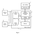
- FIG. 2 depicts one embodiment of a battery system 220 that may be used to implement the operations shown in FIGS. 4, 5, 6, 7, 8 and 9 .
- the battery system includes battery management circuitry 230 , memory 240 and the battery pack 250 .
- the battery management circuitry 230 includes a discharge controller 231 that is capable of executing the operations described in FIGS. 4, 5, 6, 7, 8 and 9 to partially discharge the battery blocks in the battery pack.
- the battery management circuitry which may be implemented at least in part by a programmed processor, is coupled to the battery pack via interconnect 260 , which is used to transmit and receive multiple control and data signals to and from the battery pack.
- the battery management circuitry may also be used to identify battery blocks with various characteristics, such as anomalous behavior.
- the battery management circuitry is also coupled to the memory 240 which is used to store information including, but not limited to, software code and data associated with executing the sequence of operations in FIGS. 4, 5, 6, 7, 8 and 9 .
- a user interface 210 is coupled to the battery management circuitry within the battery management system. This user interface is used to present (through the display device 211 ) and collect information to and from an operator of the system, the information presented including, without limitation, battery pack SOC, battery pack charging or discharging status, battery pack temperature, and electric vehicle (EV) range.
- the battery pack is coupled via positive and negative terminals 251 and 252 to an external load 280 (for example, the electric motor of the EV), and power source 290 (for example, a drive-time charging current source such as a regenerative braking system that delivers charging power during braking in an EV or HEV, or an electrical alternator or generator in an HEV).
- the battery system may include numerous other functional blocks in addition to or within the functional blocks shown, including programming and debug interfaces, maintenance and system-level data collection.
- the battery system, battery management circuitry and/or discharge controller may also include various functional logic blocks, such as status logic for determining whether the battery is in a rest state, pre-conditioning logic to draw pre-conditioning current from the battery (e.g., in response to detecting that the battery is in the rest state), voltage measurement logic to measure the OCV, state-of-charge determination logic to determine the state-of-charge of the battery based on the OCV, charge-balancing logic to balance the level of charge on the various battery blocks. Any or all of those logic blocks may be implemented by one or more programmed processors (including special-purposes processor(s), micro-controller(s), general-purpose processor(s), etc.) that execute a programmed sequence of instructions to carry out the various functions performed by the logic block.
- programmed processors including special-purposes processor(s), micro-controller(s), general-purpose processor(s), etc.
- FIG. 3 shows one embodiment of a battery pack 250 with circuitry controlled by a discharge controller (e.g., element 231 of FIG. 1 ) to discharge the battery blocks 310 contained within the battery pack.
- a discharge controller e.g., element 231 of FIG. 1
- Each battery block 310 comprises multiple battery cells 340 , along with voltage and current measurement devices, 350 and 360 respectively, which permit concurrent measurement of charging or discharging voltages and currents of all battery blocks.
- each or any of the battery blocks 310 may have more or fewer cells than shown FIG. 3 .
- a battery block may include tens, hundreds or more battery cells, while in lower power systems a battery block may be constituted by a single battery cell.
- FIG. 3 shows the battery cells in a battery block connected in parallel.
- inventions may have one or more of the battery cells connected in series. Also, while all voltage and current measurement devices are shown as being coupled to battery management circuitry 230 via the interconnect 260 , separate interconnects could alternatively be employed.
- the battery cell or cells that constitute each battery block may be implemented by any practicable battery chemistry.
- FIG. 4 illustrates one embodiment of a sequence of operations to improve the performance of a battery pack by balancing the battery blocks with reference to maximum or minimum battery pack voltages measured during the operation of the battery pack.
- the sequence utilizes an estimate of the state-of-charge of each battery block (ESOC).
- ESOC state-of-charge of each battery block
- an initial ESOC value for each battery block is determined.
- One embodiment may use an estimate of the SOC for the battery block based on a previously measured OCV. Other methods of determining the initial ESOC value may also be used.
- all of the battery blocks are balanced with reference to their ESOC value at operation 410 , an operation described in greater detail in reference to FIG. 5 .
- the sequence continues by updating the ESOC value for each block based on either statistics of aggregate block voltage margins in 420 (an example of which is described in reference FIG. 6 ) or based upon relative block voltages through the combination of tag creation and update operations in 430 (described, for example, in FIG. 7 ) and 440 (described, for example, in FIG. 8 ) respectively.
- the sequence is repeated (iterated) at 410 to balance the charge in each battery block based on the updated ESOC values for each battery block.
- the respective ESOC values for all or selected battery blocks are manipulated to force a charge balancing operation in 410 , thereby effecting relative SOC offsets between the various battery blocks to carry out the peak-equalized and/or margin-based charge balancing operations shown, for example, in FIGS. 1C and 1E .
- statistical measures of aggregate block voltage margins e.g., averaged high and low operating margins are evaluated to adjust the ESOC of all battery blocks up or down uniformly.
- operation 410 is executed in series with operations 420 and 430 / 440 , and operations 420 and 430 / 440 are executed in parallel.
- the operations 410 , 420 , 430 and 440 may be executed in series, in parallel, periodically or in response to prescribed or programmatically specified conditions or events.
- FIG. 5 illustrates an exemplary sequence of operations used to balance the charge in each of the battery blocks based on the ESOC for each block.
- the first battery block in the battery pack is selected.
- the ESOC value of the selected battery block is compared to a fixed or dynamically determined minimum value of ESOC, ESOC min .
- One embodiment may determine ESOC min based on the minimum value of all battery block ESOC values. Other embodiments may use different methods to determine ESOC min . If the battery block ESOC value is greater than ESOC min (i.e. affirmative determination at 510 ) the battery block is “balanced” in operation 520 by removing charge using the balance resistors 330 controlled by the discharge controller 231 .
- the amount of charge removed (or “bled” or “discharged”) from a given battery block may depend on a number of factors including, but not limited to, battery pack age, discharge cycles, ESOC value, temperature and/or may be specified by programming a specified value or factors to be accounted for when determining the amount of charge to remove within one or more programmable registers of the battery management circuitry shown in FIG. 2 .
- the battery blocks or any subset thereof may be actively balanced by discharging one or more battery blocks into one or more other battery blocks (e.g., transferring charge between battery blocks through a capacitive or inductive coupling circuit).
- charge may be selectively added to one or more battery blocks from an external charging source (i.e., charging a single block or at least fewer than all the battery blocks in the battery pack).
- an external charging source i.e., charging a single block or at least fewer than all the battery blocks in the battery pack.
- FIG. 6 shows an exemplary sequence of operations that adjusts the ESOC of all battery blocks uniformly based on statistics of system-wide battery block voltage margin, and thus may be used to implement ESOC update operation 420 of FIG. 4 .
- the sequence begins at 610 where the charging current flowing through the battery blocks is evaluated. If the charging current is greater than I tc , (i.e. affirmative determination at 610 ) then the sequence continues at 620 . If the charging current is less than or equal to I tc , or if the battery pack is discharging, the sequence continues at 630 . At 620 , if more than P hi percent of the battery blocks have voltages greater than V thi (i.e. affirmative determination at 620 ) then the sequence continues at 650 .
- the sequence continues at 660 .
- the ESOC of all blocks is increased by A hi , which may be a percentage of the existing ESOC value or an absolute amount.
- a hi the discharge current flowing through the battery blocks is evaluated. If the discharge current is greater than I td , (i.e. affirmative determination at 630 ), the sequence continues at 640 . If the discharge current is less than or equal to I td , then the sequence continues at 660 . At 640 , if more than P lo percent of the battery blocks have voltages less than V tlo (i.e. affirmative determination at 640 ) then the sequence continues at 670 .
- the sequence continues at 660 .
- the ESOC of all blocks is decreased by A lo , which may be a percentage of the existing ESOC value or an absolute amount.
- the sequence waits for period of time, T w .
- sequence 420 is deemed to be complete.
- the ESOC of all battery blocks is adjusted up by a predetermined amount. This ESOC increase will cause the battery blocks to be discharged in operation 410 which will consequently reduce their operating voltages and thus increase the margin between the operating limit and the battery block voltages during charging.
- the parameters I tc , I td , P hi , P lo , V thi , V tlo , A hi , A lo and T w are predetermined and fixed. In other embodiments these parameters dynamically may be calculated based on the current system operating conditions and/or based upon factors including, but not limited to battery pack age, discharge cycles, ESOC value, temperature and so forth.
- FIG. 7 shows an exemplary sequence of operations that may be executed to create tags that store (in the battery system memory 240 ) characteristics of each battery block when significant current is flowing through that battery block.
- a battery block in the battery pack is selected and becomes “the battery block” (and “the selected block”) for purposes of the remaining operations.
- the sequence proceeds to 720 . Otherwise, the battery block current is compared with a lower threshold I bmin at 710 and, if less than or equal to I bmin , the sequence continues at 715 .
- the selected battery block is tagged as having been “high tested” (i.e., tested while significant charging current is flowing into the battery pack).
- the tag itself may be effected, for example, by storing a flag or other indicator in a tag memory (e.g., within element 240 of FIG. 2 ).
- the selected block voltage is compared to a statistical combination of all other battery block voltages (the ‘pack voltage’). In one embodiment, for example, an arithmetic mean is used for the statistical combination. Different statistical combinations or other representations of the pack voltage may be used in other embodiments, such as the maximum or minimum battery block voltage in the pack or the arithmetic mean of all battery block voltages, excluding the voltage of the selected block.
- the selected block voltage is V cmaxt or more above the pack voltage (i.e. affirmative determination at 735 )
- the selected block is tagged at 745 as being “high voltage” to indicate that the block voltage is higher than the pack voltage when a significant charging current is flowing through the battery pack. Otherwise, if the difference between the selected block voltage and the pack voltage does not exceed V cmaxt (i.e., negative determination at 735 ), then the system determines at 750 whether all the battery blocks have been processed, exiting the tag creation operation if so, and selecting the next block at 755 before repeating the operations that start at decision 705 .
- the tag creation sequence continues at 715 . If the current flowing through the battery pack is a charging current or less than or equal to I bmin , the sequence continues at operation 725 where the sequence waits for a time period of T b before continuing back at 705 without changing the selected block (i.e. the same block will be evaluated again at operations 705 and 710 ). At operation 715 , the block is tagged as being “low tested”, indicating that the block has been evaluated while a significant discharging current was flowing through the battery pack. At the next operation, 730 , the selected block voltage is compared to the pack voltage.
- the sequence continues at 740 . If the difference between the selected block voltage and the pack voltage does not exceed V cmint (i.e., selected block voltage is less than V Cmint below the pack voltage), then the sequence continues at 750 .
- the block is tagged as being “low voltage”, indicating that the block has a voltage that is lower than the pack voltage when a significant discharging current is flowing through the battery pack. If additional battery blocks are available to process at operation 750 (i.e. affirmative determination at 750 ), the next block is selected at 755 and the sequence is repeated starting at 705 . Otherwise, the tag creation sequence is deemed complete.
- FIG. 8 shows an exemplary sequence of operations executed to adjust or update the estimate of SOC based upon the block tags created by the sequence shown in FIG. 7 , and thus an operational sequence that may be used to implement operation 440 of FIG. 4 .
- the first battery block in the battery pack is selected and becomes the “selected block” for the operations that follow.
- information stored in the tag memory e.g., element 140 of FIG. 1
- the tag memory is examined to determine if the selected block has been tagged as both “high tested” and “low tested”, indicating that the selected block has been evaluated both when significant charging current was flowing through the battery pack and separately when significant discharging current was flowing through the battery pack.
- the sequence continues at 815 (i.e. affirmative determination at 810 ), otherwise, the sequence continues at 850 .
- the sequence continues at 815 (i.e. affirmative determination at 810 ), otherwise, the sequence continues at 850 .
- the sequence continues at 825 , otherwise the sequence continues at 830 .
- the selected block has been tagged as both “high voltage” and “low voltage”, and is therefore an anomalous block (e.g., defective in some manner relating to its constituent battery cell(s) and/or interconnections thereto, or otherwise having significantly lower performance than other battery blocks) and thus requires anomalous adjustment. This anomalous adjustment is illustrated in FIG. 9 and described below.
- operation 825 completes, the sequence continues at 850 .
- the ESOC of the selected block is increased by A chi , which may be a percentage of the existing ESOC value or an absolute amount.
- a chi may be a percentage of the existing ESOC value or an absolute amount.
- This increase in ESOC will cause the charge in the selected block to be reduced (i.e., by virtue of operation 520 of FIG. 5 , assuming that the operations shown there are executed iteratively to detect and respond to ESOC adjustments), reducing the selected block voltage to be similar to the other battery blocks when charging current is flowing (i.e., equalizing the upper peak voltages of the blocks), thus ‘performance balancing’ the battery pack as described in reference to FIG. 1C .
- operation 835 completes, the sequence continues at 850 .
- the sequence proceeds to 840 . If the selected block has been tagged with “low voltage” (i.e. affirmative determination at 840 , indicating that the selected block may have a lower SOC than other battery blocks), then at 845 the ESOC of the selected block is decreased by A clo , which may be a percentage of the existing ESOC value or an absolute amount. This decrease in ESOC will cause the charge in the selected block to be increased relative to other battery blocks (i.e., by virtue of operations 510 and 520 of FIG.
- the battery management system determines if there are additional battery blocks to process. If there are additional battery blocks to process, the sequence loops back to operation 855 to process the next battery block (i.e., the new “selected block”). Otherwise, the ESOC update sequence is deemed complete.
- the parameters A chi and A clo are predetermined and may be programmed or fixed (i.e., established by design) within the battery management system in one embodiment. In other embodiments the battery management system may determine these parameters dynamically based on the system operating conditions and/or additional factors including, but not limited to, battery pack age, discharge cycles, ESOC value, temperature, etc.
- FIG. 9 shows an exemplary sequence of operations that adjust the estimate of SOC for an anomalous block that is defective in some manner or has significantly lower performance than other battery blocks.
- the operations shown in FIG. 9 trigger the change in battery block charge (and consequently SOC) that results in the margin-based balancing described in reference to FIG. 1E .
- Starting at operation 905 it is determined if either maximum power or maximum capacity is required from the battery pack. For example, if the battery pack is installed in an electric vehicle, with the battery pack as the sole motive power source, it may be preferably to maximize battery pack capacity instead of power and thus maximize vehicle driving range. Conversely, if the battery pack is installed in a hybrid electric vehicle, maximum power, providing enhanced vehicle acceleration and braking, may be preferred.
- the sequence completes and the ESOC of the block is not adjusted. If maximum power is required from the battery pack then the sequence continues at 810 .
- analysis of block voltages during charging and discharging is performed to determine if the block voltage is closer to the operating limit during charging or during discharging. If closer during discharging, the sequence continues at 920 , otherwise the sequence continues at 915 .
- the ESOC of the block is increased by A cphi . This increase in ESOC will cause the charge in the selected block to be reduced (i.e., by virtue of operation 520 of FIG. 5 ), providing more margin between the battery block charging voltage and the high operating limit voltage and thus equalizing the upper and lower operating margins (and also reducing the anomalous block voltage to be similar to the other battery blocks when charging current is flowing).
- the ESOC of the block is decreased by A cplo .
- This decrease in ESOC will cause the charge in the anomalous block to be increased relative to other battery blocks (i.e., by virtue of operations 510 and 520 of FIG. 5 ), providing more margin between the battery block discharging voltage and thus equalizing the upper and lower operating margins (and also increasing the anomalous block voltage to be similar to the other battery blocks when discharging current is flowing).
- a cphi and A cplo may be predetermined and programmatically specified or fixed by design. Alternatively, these parameters may be determined dynamically based on system operating conditions and/or additional factors including, but not limited to, battery pack age, discharge cycles, ESOC value, temperature, etc.
- Device or system “programming” may include, for example and without limitation, loading a control value into a register, one-time programmable-circuit (e.g., blowing fuses within a configuration circuit during device production) or other storage circuit within an integrated circuit device of the host system (or host device) and thereby control an operational aspect of the host system or establish a host system configuration.
Landscapes
- Engineering & Computer Science (AREA)
- Power Engineering (AREA)
- Life Sciences & Earth Sciences (AREA)
- Sustainable Development (AREA)
- Sustainable Energy (AREA)
- Transportation (AREA)
- Mechanical Engineering (AREA)
- Manufacturing & Machinery (AREA)
- Chemical & Material Sciences (AREA)
- Chemical Kinetics & Catalysis (AREA)
- Electrochemistry (AREA)
- General Chemical & Material Sciences (AREA)
- Secondary Cells (AREA)
- Charge And Discharge Circuits For Batteries Or The Like (AREA)
Abstract
Description
Claims (24)
Priority Applications (1)
| Application Number | Priority Date | Filing Date | Title |
|---|---|---|---|
| US13/434,678 US9728820B2 (en) | 2012-03-29 | 2012-03-29 | Margin-based battery charge balancing |
Applications Claiming Priority (1)
| Application Number | Priority Date | Filing Date | Title |
|---|---|---|---|
| US13/434,678 US9728820B2 (en) | 2012-03-29 | 2012-03-29 | Margin-based battery charge balancing |
Publications (2)
| Publication Number | Publication Date |
|---|---|
| US20130257323A1 US20130257323A1 (en) | 2013-10-03 |
| US9728820B2 true US9728820B2 (en) | 2017-08-08 |
Family
ID=49234002
Family Applications (1)
| Application Number | Title | Priority Date | Filing Date |
|---|---|---|---|
| US13/434,678 Active 2035-05-23 US9728820B2 (en) | 2012-03-29 | 2012-03-29 | Margin-based battery charge balancing |
Country Status (1)
| Country | Link |
|---|---|
| US (1) | US9728820B2 (en) |
Cited By (3)
| Publication number | Priority date | Publication date | Assignee | Title |
|---|---|---|---|---|
| US20190039476A1 (en) * | 2017-08-02 | 2019-02-07 | Next-E Solutions Inc. | Management device, electric storage device, electric storage system and electric apparatus |
| US20190324090A1 (en) * | 2018-04-23 | 2019-10-24 | Hyundai Motor Company | Energy storage system for vehicle |
| US11223212B2 (en) * | 2018-10-26 | 2022-01-11 | Toyota Jidosha Kabushiki Kaisha | Battery control device for homogenizing battery cells |
Families Citing this family (21)
| Publication number | Priority date | Publication date | Assignee | Title |
|---|---|---|---|---|
| US9450426B2 (en) * | 2011-03-07 | 2016-09-20 | A123 Systems Llc | Method for opportunistically balancing charge between battery cells |
| EP2645524B1 (en) * | 2012-03-30 | 2015-10-14 | EH Europe GmbH | Method and apparatus for battery charging |
| US9205750B2 (en) * | 2013-07-23 | 2015-12-08 | Ford Global Technologies, Llc | Method to estimate battery open-circuit voltage based on transient resistive effects |
| US10063069B1 (en) | 2014-05-23 | 2018-08-28 | Artisan Vehicle Systems Inc. | Module maintenance system |
| US9960396B2 (en) | 2013-09-24 | 2018-05-01 | Artisan Vehicle Systems Inc. | Module backbone system |
| DE102014200619A1 (en) * | 2014-01-15 | 2015-07-16 | Robert Bosch Gmbh | Method for charge state compensation of a battery |
| US20160003911A1 (en) * | 2014-07-03 | 2016-01-07 | Infineon Technologies Ag | Battery cell characteristic identification |
| JP6883396B2 (en) * | 2016-08-25 | 2021-06-09 | 矢崎総業株式会社 | Quick charging device |
| US10291046B2 (en) * | 2016-11-23 | 2019-05-14 | Robert Bosch Gmbh | Method for fast charging lithium-ion batteries |
| CN106828155B (en) * | 2017-01-14 | 2018-12-21 | 张化锴 | A kind of electrokinetic cell system Homogeneity between groups circuit and equalization methods |
| CN109435773B (en) * | 2017-08-31 | 2022-02-08 | 比亚迪股份有限公司 | Battery equalization method, system, vehicle, storage medium and electronic device |
| CN110015189B (en) * | 2017-08-31 | 2022-05-13 | 比亚迪股份有限公司 | Battery equalization method, system, vehicle, storage medium and electronic device |
| CN108099636B (en) * | 2017-11-23 | 2021-04-06 | 朱颖 | Device and method for balancing and protecting battery pack |
| US10355496B1 (en) * | 2018-07-26 | 2019-07-16 | Kitty Hawk Corporation | Inter-module battery balancing using minimum cell voltages to select battery sub-modules to power loads |
| US10608442B1 (en) | 2018-09-24 | 2020-03-31 | Texas Instruments Incorporated | Adaptive cell-balancing |
| CN111993953B (en) * | 2020-08-27 | 2021-10-29 | 安徽江淮汽车集团股份有限公司 | Battery control method, power automobile and readable storage medium |
| US11791642B2 (en) | 2020-10-08 | 2023-10-17 | Element Energy, Inc. | Safe battery energy management systems, battery management system nodes, and methods |
| US10992149B1 (en) | 2020-10-08 | 2021-04-27 | Element Energy, Inc. | Safe battery energy management systems, battery management system nodes, and methods |
| US11699909B1 (en) * | 2022-02-09 | 2023-07-11 | Element Energy, Inc. | Controllers for managing a plurality of stacks of electrochemical cells, and associated methods |
| US20240291287A1 (en) * | 2022-02-09 | 2024-08-29 | Element Energy, Inc. | Controllers for managing a plurality of stacks of electrochemical cells, and associated methods |
| US11664670B1 (en) | 2022-08-21 | 2023-05-30 | Element Energy, Inc. | Methods and systems for updating state of charge estimates of individual cells in battery packs |
Citations (13)
| Publication number | Priority date | Publication date | Assignee | Title |
|---|---|---|---|---|
| US5504415A (en) * | 1993-12-03 | 1996-04-02 | Electronic Power Technology, Inc. | Method and apparatus for automatic equalization of series-connected batteries |
| US6184656B1 (en) * | 1995-06-28 | 2001-02-06 | Aevt, Inc. | Radio frequency energy management system |
| US20030076074A1 (en) * | 2001-10-23 | 2003-04-24 | Nec Corporation | Method for charging and discharging a nonaqueous electrolyte secondary battery |
| US6984961B2 (en) * | 2002-01-17 | 2006-01-10 | Matsushita Electric Industrial Co., Ltd. | Battery assembly system and electric-motor vehicle system using the same |
| US20060077603A1 (en) * | 2004-09-07 | 2006-04-13 | Kim Jong S | Protective circuit for a secondary battery pack and method of operating the same |
| US7400113B2 (en) * | 2001-03-30 | 2008-07-15 | Designline International Holdings, Llc | Battery management unit, system and method |
| US20090085516A1 (en) * | 2007-09-28 | 2009-04-02 | Hitachi, Ltd. | Automotive Power Supply System |
| US20100019724A1 (en) * | 2008-07-24 | 2010-01-28 | Kabushiki Kaisha Toshiba | Battery system using secondary battery |
| US20110112781A1 (en) * | 2009-11-12 | 2011-05-12 | Gm Global Technology Operations, Inc. | Method for estimating battery degradation in a vehicle battery pack |
| US20120025769A1 (en) * | 2009-03-26 | 2012-02-02 | Hitachi Vehicle Energy, Ltd. | Battery System for Vehicle |
| US20130043840A1 (en) * | 2011-08-16 | 2013-02-21 | GM Global Technology Operations LLC | Systems and methods for performing cell balancing in a vehicle using cell capacities |
| US20140049222A1 (en) * | 2011-03-07 | 2014-02-20 | A123 Systems, Inc | Method for Opportunistically Balancing Charge Between Battery Cells |
| US8798832B2 (en) * | 2009-03-27 | 2014-08-05 | Hitachi, Ltd. | Electric storage device |
-
2012
- 2012-03-29 US US13/434,678 patent/US9728820B2/en active Active
Patent Citations (13)
| Publication number | Priority date | Publication date | Assignee | Title |
|---|---|---|---|---|
| US5504415A (en) * | 1993-12-03 | 1996-04-02 | Electronic Power Technology, Inc. | Method and apparatus for automatic equalization of series-connected batteries |
| US6184656B1 (en) * | 1995-06-28 | 2001-02-06 | Aevt, Inc. | Radio frequency energy management system |
| US7400113B2 (en) * | 2001-03-30 | 2008-07-15 | Designline International Holdings, Llc | Battery management unit, system and method |
| US20030076074A1 (en) * | 2001-10-23 | 2003-04-24 | Nec Corporation | Method for charging and discharging a nonaqueous electrolyte secondary battery |
| US6984961B2 (en) * | 2002-01-17 | 2006-01-10 | Matsushita Electric Industrial Co., Ltd. | Battery assembly system and electric-motor vehicle system using the same |
| US20060077603A1 (en) * | 2004-09-07 | 2006-04-13 | Kim Jong S | Protective circuit for a secondary battery pack and method of operating the same |
| US20090085516A1 (en) * | 2007-09-28 | 2009-04-02 | Hitachi, Ltd. | Automotive Power Supply System |
| US20100019724A1 (en) * | 2008-07-24 | 2010-01-28 | Kabushiki Kaisha Toshiba | Battery system using secondary battery |
| US20120025769A1 (en) * | 2009-03-26 | 2012-02-02 | Hitachi Vehicle Energy, Ltd. | Battery System for Vehicle |
| US8798832B2 (en) * | 2009-03-27 | 2014-08-05 | Hitachi, Ltd. | Electric storage device |
| US20110112781A1 (en) * | 2009-11-12 | 2011-05-12 | Gm Global Technology Operations, Inc. | Method for estimating battery degradation in a vehicle battery pack |
| US20140049222A1 (en) * | 2011-03-07 | 2014-02-20 | A123 Systems, Inc | Method for Opportunistically Balancing Charge Between Battery Cells |
| US20130043840A1 (en) * | 2011-08-16 | 2013-02-21 | GM Global Technology Operations LLC | Systems and methods for performing cell balancing in a vehicle using cell capacities |
Cited By (6)
| Publication number | Priority date | Publication date | Assignee | Title |
|---|---|---|---|---|
| US20190039476A1 (en) * | 2017-08-02 | 2019-02-07 | Next-E Solutions Inc. | Management device, electric storage device, electric storage system and electric apparatus |
| US11027614B2 (en) * | 2017-08-02 | 2021-06-08 | Next-E Solutions Inc. | Management device, electric storage device, electric storage system and electric apparatus for managing charging and discharging of a plurality of electric storage cells connected in series |
| US20190324090A1 (en) * | 2018-04-23 | 2019-10-24 | Hyundai Motor Company | Energy storage system for vehicle |
| US10859634B2 (en) * | 2018-04-23 | 2020-12-08 | Hyundai Motor Company | Energy storage system for vehicle |
| US11223212B2 (en) * | 2018-10-26 | 2022-01-11 | Toyota Jidosha Kabushiki Kaisha | Battery control device for homogenizing battery cells |
| US11626742B2 (en) | 2018-10-26 | 2023-04-11 | Toyota Jidosha Kabushiki Kaisha | Battery control device for homogenizing battery cells |
Also Published As
| Publication number | Publication date |
|---|---|
| US20130257323A1 (en) | 2013-10-03 |
Similar Documents
| Publication | Publication Date | Title |
|---|---|---|
| US9728820B2 (en) | Margin-based battery charge balancing | |
| US10690725B2 (en) | Battery state-of-charge estimation | |
| US20130257381A1 (en) | Peak-equalized battery charge balancing | |
| US9885757B2 (en) | Method and apparatus for determining the state-of-charge of a battery | |
| JP6300567B2 (en) | Secondary battery system | |
| JP6111275B2 (en) | Battery control device | |
| JP6084225B2 (en) | Battery control device, secondary battery system | |
| JP6101714B2 (en) | Battery control device, battery system | |
| EP3171187B1 (en) | Battery state detection device, secondary battery system, program product, and battery state detection method | |
| EP3171186B1 (en) | Battery state detection device, secondary battery system, program product, and battery state detection method | |
| KR101813461B1 (en) | Method for transmitting data in a battery management system | |
| US9768624B2 (en) | Method for cell balancing for a plurality of battery cells, and battery system for performing such a method | |
| CN103424710A (en) | Modeling changes in the state-of-charge open circuit voltage curve by using regressed parameters in a reduced order physics based model | |
| CN106463988B (en) | Battery control device | |
| CN105917518A (en) | Method for equalising charge state in battery | |
| CN106168644B (en) | Manual maintenance decoupler fuse state determines system and method | |
| WO2019230131A1 (en) | Charge control device, transport device, and program | |
| US20220219567A1 (en) | Systems and Methods for Maintaining Battery Health | |
| KR101261149B1 (en) | Method for estimating state of charge of battery | |
| US9065278B2 (en) | Systems and methods for evaluating and controlling a battery system |
Legal Events
| Date | Code | Title | Description |
|---|---|---|---|
| AS | Assignment |
Owner name: ATIEVA, INC., CALIFORNIA Free format text: ASSIGNMENT OF ASSIGNORS INTEREST;ASSIGNORS:DIAMOND, STEVEN;RISK, GABRIEL;HU, STANLEY;AND OTHERS;SIGNING DATES FROM 20120402 TO 20120816;REEL/FRAME:032131/0499 |
|
| AS | Assignment |
Owner name: TRINITY CAPITAL FUND III, L. P., ARIZONA Free format text: INTELLECTUAL PROPERTY SECURITY AGREEMENT;ASSIGNOR:ATIEVA, INC;REEL/FRAME:042125/0897 Effective date: 20170331 |
|
| STCF | Information on status: patent grant |
Free format text: PATENTED CASE |
|
| AS | Assignment |
Owner name: YINLONG ELECTRIC VEHICLE (HK) GROUP LIMITED, HONG KONG Free format text: SECURITY INTEREST;ASSIGNORS:ATIEVA, INC.;ATIEVA USA, INC;REEL/FRAME:044457/0942 Effective date: 20171027 Owner name: YINLONG ELECTRIC VEHICLE (HK) GROUP LIMITED, HONG Free format text: SECURITY INTEREST;ASSIGNORS:ATIEVA, INC.;ATIEVA USA, INC;REEL/FRAME:044457/0942 Effective date: 20171027 |
|
| AS | Assignment |
Owner name: ATIEVA INC., CAYMAN ISLANDS Free format text: ASSIGNMENT OF ASSIGNORS INTEREST;ASSIGNOR:ATIEVA USA INC.;REEL/FRAME:046696/0236 Effective date: 20180808 |
|
| AS | Assignment |
Owner name: AVB METRICS, LLC, CALIFORNIA Free format text: RELEASE BY SECURED PARTY;ASSIGNOR:TRINITY CAPITAL FUND III, L.P.;REEL/FRAME:047529/0619 Effective date: 20180912 Owner name: ATIEVA, INC., CAYMAN ISLANDS Free format text: RELEASE BY SECURED PARTY;ASSIGNOR:TRINITY CAPITAL FUND III, L.P.;REEL/FRAME:047529/0619 Effective date: 20180912 Owner name: ATIEVA USA, INC., CALIFORNIA Free format text: RELEASE BY SECURED PARTY;ASSIGNOR:TRINITY CAPITAL FUND III, L.P.;REEL/FRAME:047529/0619 Effective date: 20180912 |
|
| AS | Assignment |
Owner name: ATIEVA USA, INC., CALIFORNIA Free format text: RELEASE BY SECURED PARTY;ASSIGNOR:YINLONG ELECTRIC VEHICLE (HK) GROUP LIMITED;REEL/FRAME:047620/0451 Effective date: 20180914 Owner name: ATIEVA, INC., CAYMAN ISLANDS Free format text: RELEASE BY SECURED PARTY;ASSIGNOR:YINLONG ELECTRIC VEHICLE (HK) GROUP LIMITED;REEL/FRAME:047620/0451 Effective date: 20180914 Owner name: AVB METRICS, LLC, CALIFORNIA Free format text: RELEASE BY SECURED PARTY;ASSIGNOR:YINLONG ELECTRIC VEHICLE (HK) GROUP LIMITED;REEL/FRAME:047620/0451 Effective date: 20180914 |
|
| AS | Assignment |
Owner name: AYAR THIRD INVESTMENT COMPANY, SAUDI ARABIA Free format text: SECURITY INTEREST;ASSIGNOR:ATIEVA, INC.;REEL/FRAME:047199/0221 Effective date: 20180916 |
|
| AS | Assignment |
Owner name: ATIEVA, INC., CALIFORNIA Free format text: RELEASE BY SECURED PARTY;ASSIGNOR:AYAR THIRD INVESTMENT COMPANY;REEL/FRAME:048811/0472 Effective date: 20190402 |
|
| FEPP | Fee payment procedure |
Free format text: ENTITY STATUS SET TO UNDISCOUNTED (ORIGINAL EVENT CODE: BIG.); ENTITY STATUS OF PATENT OWNER: LARGE ENTITY |
|
| MAFP | Maintenance fee payment |
Free format text: PAYMENT OF MAINTENANCE FEE, 4TH YEAR, LARGE ENTITY (ORIGINAL EVENT CODE: M1551); ENTITY STATUS OF PATENT OWNER: LARGE ENTITY Year of fee payment: 4 |