US972792A - Fleshing, unhairing, working-out, and setting machine. - Google Patents
Fleshing, unhairing, working-out, and setting machine. Download PDFInfo
- Publication number
- US972792A US972792A US53719010A US1910537190A US972792A US 972792 A US972792 A US 972792A US 53719010 A US53719010 A US 53719010A US 1910537190 A US1910537190 A US 1910537190A US 972792 A US972792 A US 972792A
- Authority
- US
- United States
- Prior art keywords
- frame
- cylinder
- working
- bolster
- cylinders
- Prior art date
- Legal status (The legal status is an assumption and is not a legal conclusion. Google has not performed a legal analysis and makes no representation as to the accuracy of the status listed.)
- Expired - Lifetime
Links
- 239000000463 material Substances 0.000 description 45
- 230000033001 locomotion Effects 0.000 description 30
- 239000010985 leather Substances 0.000 description 19
- 239000002184 metal Substances 0.000 description 6
- 230000002787 reinforcement Effects 0.000 description 5
- 230000003014 reinforcing effect Effects 0.000 description 5
- 230000000694 effects Effects 0.000 description 4
- 230000002441 reversible effect Effects 0.000 description 4
- 238000010276 construction Methods 0.000 description 3
- 230000000881 depressing effect Effects 0.000 description 2
- 239000011435 rock Substances 0.000 description 2
- 241001446467 Mama Species 0.000 description 1
- 229910000831 Steel Inorganic materials 0.000 description 1
- 230000001419 dependent effect Effects 0.000 description 1
- 210000004209 hair Anatomy 0.000 description 1
- 239000002245 particle Substances 0.000 description 1
- 230000000284 resting effect Effects 0.000 description 1
- 239000010959 steel Substances 0.000 description 1
Images


Classifications
-
- C—CHEMISTRY; METALLURGY
- C14—SKINS; HIDES; PELTS; LEATHER
- C14B—MECHANICAL TREATMENT OR PROCESSING OF SKINS, HIDES OR LEATHER IN GENERAL; PELT-SHEARING MACHINES; INTESTINE-SPLITTING MACHINES
- C14B1/00—Manufacture of leather; Machines or devices therefor
- C14B1/02—Fleshing, unhairing, samming, stretching-out, setting-out, shaving, splitting, or skiving skins, hides, or leather
- C14B1/04—Fleshing, unhairing, samming, stretching-out, setting-out, shaving, splitting, or skiving skins, hides, or leather using slicking, scraping, or smoothing-out cylinders or blades fixed on supports, e.g. cylinders, in a plane substantially at right angles to the working surface
- C14B1/10—Fleshing, unhairing, samming, stretching-out, setting-out, shaving, splitting, or skiving skins, hides, or leather using slicking, scraping, or smoothing-out cylinders or blades fixed on supports, e.g. cylinders, in a plane substantially at right angles to the working surface in machines with drums with cylindrical, conical, or similar surfaces for supporting the whole working piece
Definitions
- H ALEFS FLESHING, UNHAIBING, WORKING-OUT, AND SETTING MAGHINE.
- ALEFS FLESHING, UNHAIBING, WORKING-OUT,'AND SETTING MACHINE.
- This invention has for its object to provide a hide and leather working machine performing the usual functions of fieshing, unhairing, working-out and setting machines in a simple and more efficient manner than heretofore, and comprises a swinging cylinder frame provided with a cylinderof appropriate construction for the work to be performed and cooperating with a concave flexible work-supporting bolster having a stiff backing unyielding to local irregularities in the material worked upon, but yielding bodily to a general pressure thereon to suit its position to the thickness of the material.
- Another object of the invention is to provide such backing for the flexible holster with its ends independently adjustable with relation to the path of the working cylinder to produce a uniform treatment throughout the surface of the material operated upon, notwithstanding a difference in thickness of said material at the respective ends of the machine.
- Another object of the invention is to'provide the swinging cylinder frame in such hide and leather working machines with a pair of working cylinders to work simultaneously upon the material so as to complete the operation in one operative movement of the cylinder frame.
- Another object of the invention is to provide a novel form of clamping means for clamping the material operated upon.
- Another object of the invention is to pro vide means of novel construction for giving tension to the flexiblebolster.
- the invention consists in the construction and relative arrangement of certain parts and in combinations of parts hereinafter particularly described and pointed out in the claims.
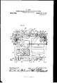
- Figure 1 is a side elevation of a hide and leather working machine constructed in accordance with this invention, parts being broken away and an operative position for the cylinder frame leeing shown in dotted lines;
- Fig. 2 is a plan view thereof with parts in section;
- Fig. 3 is a rear elevation thereof with one of the rear intermediate frames broken away to show the side edge of the bolster;
- Fig. 1 is a view similar to Fig. 1 of a portion of the machine, showing the swinging frame in its. uppermost position:
- 10 indicates a pair of end frames and 11 and 12 respectively indicate a pair of front and rear intermediate frames, there being various rods and beams 13 connecting these frames together to form a rigid supporting structure.
- a feed shaft 14 carrying a belt pulley 15 by means of which it may be driven from any suitable source of power.
- the feed shaft 14 is provided with a gear wheel 16 and a sprocket wheel 17, the gear wheel meshing with a gear wheel 18 and the sprocket wheel being connected by means of a chain 19 with a sprocket wheel 20, both of which are loosely mounted on a reversible shaft 21' also journaled in bearings across the rear part of the machine.
- double clutch 22 connects either the gear wheel 18 or the sprocket wheel 20 to the reversible shaft 21 or disconnectsboth of them, so that said shaft 21may be driven in either direction from the feed shaft 14 or it may remain at rest.
- a yoked lever 23 for throwing the double clutch 22. is mounted on the frame of the machine and is connected by a link 24 to a crank arm 25 on a rock shaft '26 extending across one side of the machine, there being another crank arm 27 on said rock shaft at the front of the machine to which a'handle 28 is connected and extends through a suitable guide to ventionybut it is to be'understoo that the I a position in convenient access'to the operator who stands near the middle of the front of the machine.
- the double clutch 22 By moving the handle 28 to the right or the left .of the position in which it is shown in Fig. 2 the double clutch 22 is moved in one direction or the other to effect either of the driving connections for the shaft 21.
- the reverslble shaft'21 has pinions 29 fixed on it near its ends meshing with gear wheels 30 loosely mounted on a drive shaft 31 which is also suitably journaled across the rear part of the frame.
- a tubular sleeve 33 which has clamped on its ends the side arms 34 of the swinging cylinder frame, there being a cross bar 35 connecting the side arms 34 so as to complete a rigid frame therewith which is free to swing upon the axis of the shaft 31 as a center.
- a shaft 36 is journaled across the cylinder frame in the arms 34 thereof and has sprocket wheels 37 and pinions 38 keyed to its ends, said sprocket wheels being connected by chains 39 with sprocket wheels 40 connected with or forming part of the gear wheels 30.
- the pinions 38 are driven by the direct or reverse drive connection made by the double clutch 22 and serve to roduce the swinging movements of the cyhnder frame by meshingwith arcshaped racks 41 secured to the end frames 10.
- an automatic control is provided therefor,'which'comprises a pair of cams 42 and 43 fixed on the sleeve 33 in position to engage a'projection 44 of theyoked lever 23 when the cylinder frame reaches the end of its movement in either direction.
- sprocket wheels 46 which fit within the adjustable bearings, have sprocket wheels 46 on their ends with chains 47 passing around, the sprocket wheels 46 of both cylinders and also around sprocket wheels 48 which are keyed on the drive shaft 31 and are positioned between the sprocket wheels 40 and the ends of sleeve 33.
- the working cylinders are thereby driven directly from the shaft 31 in all positions of the cylinder frame, a clutch controlled belt pulley 49 being mounted on one end of said shaft 31 by means of which it receives motion-from an engine or the like.
- clamping bar 53 by means of downwardly projecting brackets 54, which clamping bar is adapted to cooperate with a cushioning member 55 on one of the cross beams 13 of the frame for clamping the hide or leather between them when the clamping frame is 1n its lower position.
- cam hooks 56 are provided at the ends of the clamping bar 53 and are adapted to engage beneath rollers 57 mounted on the cross beam 13, there being rollers 58 carried by the ends of arms 34 to bear against the curved rear edges of said hooks for forcing them beneath the rollers 57 during the downward movement of the cylinder frame and to bear against the projecting tail portions of said hooks for withdrawing them from beneath the rollers 57 on the upward movement of the cylinder frame.
- the rollers 58 leave the hooks 56 as soon as the engagement or dis-' engagement thereof is accomplished, so that the cylinder frame may continue its movement.
- the arms 34 of the cylinder'frame have a rod 59 connecting them which carrier rollers 60 to engage the under surface of the arms 50 and cause the clamping frame to rise with the cylinder frame assoon as the hooks 56 have become disengagedv from the rollers 57, and said clampingframe will follow the cylinder frame in its :dOWIlward movements until it engages the ma-' terial on the cushioning member 55, when 1 the further movement of the cylinder frame effects the clamping by the cam action of the hook members 56 on the rollers 57 ,the clamping frame being left in its clamping position during the operative movements of the cylinder frame.
- a flexible rubber bolster 61 extending the full width of the cylinders 45 has its upper edge secured to the cross beam 13 beneath the cushioning member 55 and hangs flexed in approximately the arc of the path of movement of the cylinders withits lower end wound about a drum 62.
- the drum 62 is fixed on a shaft 63 which is journaledin the frame with sleeves 64 interposed between it and its bearings, said sleeves having plates 65 at one end bearing against the outside of the end frames 10 and carrying pawls 66 to engage the teeth of ratchet wheels 67 which are fixed on the shaft 63, while the other ends of the sleeves are connected to the inner ends of coil springs 68- surrounding them and connected at their outer ends to the frame at 69.
- the springs 68 are right and left springs and their ratchets and pawls are correspondingly arranged so as to have the same effect upon the drum though located at opposite ends thereof, and when it is desired to take up some slack of the bolster, this may. be done by applying wrenches to the squared ends of the shaft 63 and turning it so that the ratchet wheels 67 move beneath the pawls 66 to new positions of engagement therewith, thus turning more of the bolster upon the drum.
- the bolster alone is not relied upon for furnishing the backing or support to hold the hide or leather against the working cylinders during their operation, for it has been found in practice that flexible bolsters without a more rigid backing or reinforcement than a leather apron or other flexible reinforcement will bag in the center and thus result in an uneven engagement of the material with the cylinders and an uneven effect produced upon the article treated. It is therefore an object of this invention to provide the flexible bolster with a stiff backing which will be unyielding to slight pressures of local irregularities in the surface of the material, but which will be spring supported so as to yield bodily to a general pressure at any part thereof, thus enabling the treatment of thin material and thick material without readjustment.
- the backing should be in a position where it will hold the thinnest material placed on the bolster in proper position relative to the path of the working cylinders and yield bodily to the increased pressure brought to bear thereon as the working cylinders travel over the heavier material, so as to prevent a too vigorous action of the working rollers on said material which might injure the same.
- the bodily yielding reinforcement or backing for the bolster may consist of a sheet metal plate 70, such as boiler plate, which is yieldingly mounted on spring members 71 carried by' arc shaped frames 72.
- the details of these spring members are shown in Fig. 6, which represents the uppermost spring member on one of the frames 72 to which the plate is fastened by means of countersunk screws 73.
- the other spring members are similar but without the screw connection with the plate 70, said plate merely resting thereon.
- the spring member 71 is in the form of a hollow plunger fitting Within a housing 74: of the frame 72 and containing a coil spring 75 which bears at one end against the plunger and at the other end against the flanged end of a sleeve 76 which is threaded for adjustment through the end of the housing 74 and has a stem 77 from the plunger passing through it, the outer end of the sleeve 76 being squared to facilitate its adjustment and the outer end of the stem 77 having a pair of jam nuts 78 threaded thereon to determine the normal position of the plunger and thereby the normal position of the plate 70.
- the frames 72 may be rigidly mounted, but for the purpose of facilitating certain classes of work performed by the machine, such as working-out and setting, where the cylinders should engage the material when moving in one direction only, it is desirable to so mount the frames 72 that they may be advanced into operative position or withdrawn therefrom at will, so that the cylinders may be effective during their downward movement, but will not engage the material during their upward movement, a suflicient slack being given to the bolster 61 at such times by the adjustment of the ratchet wheels 67 to permit it to drop away from the path of the cylinders when the frames 72 are retracted.
- This adjustability of the frames 72 may be accomplished as here shown, by mounting them upon levers 79 which are fulcrumed on the main frame and have slot connections with the ends of frames 72, there being links 80 connecting the frames 72 with the main frame to suspend them and relieve the levers 79 of the weight thereof.
- the levers 79 are operated simultaneously by having turn buckle'connections 81 with spring retracted treadles 82, there preferably being two of said treadles located side by side at any desired elevation at the front of the machine within convenient reach of the operator and adapted to be operated individually or simultaneously and to a greater or less degree.
- a difference in the extent of operation of the two treadles results in one end of the plate 70 being advanced nearer to the path of the working cylinders than the other and thereby adapts the machine for work upon material of varying thickness from side to side. hen the machine is performing work which does not require the withdrawal of the backing plate 70, as in fleshing or unhairing, both treadles are locked in their lowermost position by means of cams 83 or in any other convenient manner.
- the clamping frame moves downwardly with the cylinder frame until the clamping member 53 engages the material and then the rollers 58 of the cylinder frame, by riding over the rounded rear edges of the hooks 56, force the cam ends of said hooks beneath the rollers 57 and thereby tightly clamp the clamping member upon the material to prevent its slipping.
- the cylinder frame continues its downward movement, bringing both of the cylinders 45 into operative relation with the material on the bolster and depressing the bolster until it bears against its backing plate 70, where it receives a firm reinforcement which will cause the material to be held firmly against theworking blades of the cylinders, though such backing will yield sufficiently when occasion requires to prevent the blades of the cylinders from cutting into the body of a thick piece of material.
- the cylinder frame At any point in the movement of the cylinder frame it may be arrested or reversed and again continued in its downward movements in order to thoroughly perform the work required of it by the manipulation of the handle 28, but, by reason of the frame being provided with two cylinders instead of one, the usual second travel of the cylinder is obviated and the entire work may be performed by the single travel of the cylinder frame over the material.
- the cylinder frame When the cylinder frame reaches the end of its downward movement it is returned to its normal position either by the operation of the handle 28 or automatically by the engagement of the cam 43 with the clutch arm 44.
- the backing plate When the machine is used for fleshing, the backing plate prevents the material being crowded away from the path of the cylinder blades so that they are effective to remove all particles of adhering flesh and dirt from the hide, said plate only yielding to the pressure of the cylinders when the thickness of the hide itself renders that necessary.
- the backing plate 70 forms a platen for firmly supporting the leather to receive the action of the cylinders, which of course are modified as usual to properly perform their functions.
- the flexible bolster under the tension of springs the material is held closely against the cylinders so that every part thereof is brought into active relation with the cylinders, but upon the cylinder blades meeting with a local thicker portion in the operation of fleshing, instead of said thicker portion avoiding the action of the cylinder blades by depressing the flexible bolster at that point, the plate 70 reinforcing the bolster prevents such local depression and holds the thicker portion to the action of the cylinder blades so that it is reduced and the operation is made uniform throughout the surface of the material. It will be understood that the yielding of the plate 70 to the hide of greater thickness is due to the increased pressure brought to bear thereon throughout its surface or a" large portion thereof and that such yielding would not take place upon the rollers passing a local enlargement only.
- the cylinders may be made to actively engage the material on their downward movement and then returnto their upper position without engaging the material, and
- the reinforcing plate 70 when one end of the reinforcing plate is adjusted nearer to the axis of movement of the cylinder frame than the other it is adapted for accommodating material which is thicker at one edge than at the other. It is obvious that the spring means for the reinforcing plate 70 may be made sufiiciently sensitive to permit the plate to adjust itself to accommodate hides of varying thickness from side to side.
- hide and leather working machine as employed herein is intended to include such machines as are adapted to perform any of the various functions herein mentioned or substantial equivalents thereof.
- a hide and leather working machine comprising a swinging cylinder frame, a working cylinder carried thereby, a flexible bolster mounted in the path of the working cylinder for holding the material in an operative relation to the working cylinder, and a stiff yielding backing for the bolster spaced therefrom and concentric with the axis of swinging movement of the cylinder frame to prevent yielding of the bolster to local irregularities in the thickness of the material, but permitting the bolster to yield to accommodate material of different general thickness.
- a hide and leather working machine comprising a frame, a cylinder frame pivotally mounted to swing thereon, a suitably driven working cylinder carried by the cylinder frame, a flexible bolster supported by the frame in a position to be engaged by the working cylinder and adapted to support material and present it in an operative relation to the cylinder, and a stiff metal plate yieldingly mounted on the frame at a distance from the bolster and concentric to the pivotal mounting of the cylinder frame and forming a reinforcement or backing for the bolster.
- a hide and leather working machine comprising a frame, a cylinder frame mounted thereon to have a swinging movement, a working cylinder carried by the cylinder frame, a flexible bolster supported by the frame and extending in the path of the working cylinder, a stiff metal platespaced from the bolster and concentric with the axis of swinging movement of the cylinder axis of the cylinder frame to accommodate work of different thickness and work of .axis of the cylinder frame, and spring members carried by the spring frames and yieldingly supporting the metal plate whereby the metal plate forms a reinforcing backing for the bolster which may be moved into operative or inoperative relation to the working cylinder or inclined to accommodate work of tapering thickness.
- a hide and leather working machine comprising a frame, a cylinder frame mounted to swing thereon, a working cylinder carried by the cylinder frame, a flexible bolster having one end connected with the frame, and a spring actuated drum mounted on the frame and having the other end of the bolster connected therewith for holding the bolster under tension in the path of the working cylinder.
- a hide and leather working machine comprising a frame, a cylinder frame mounted to swing thereon, a working cylinder carried by the cylinder frame, a flexible bolster having one end connected with the frame, a drum mounted on the frame and having the other end of the bolster connected therewith, springs connected with the frame, and ratchet connections between the springs and the drum for giving an adjustable spring action to the drum to hold the bolster under tension in the path of the working cylinder.
- a hide and leather working machine comprising a frame, a cylinder frame mounted to swing thereon, means for swinging the cylinder frame, a bolster on the frame to support the material to be treated, a pair of cylinders mounted on the cylinder frame and adapted to simultaneously operate upon the material on the bolster, and driving means for turning the cylinders during the swinging movements of the cylinder frame.
- a hide and leather working machine comprising a frame, a suitably driven shaft journaled on the frame, a cylinder frame pivotally mounted on the shaft, a pair of cylinders journaled in the outer end of the cylinder frame, sprocket wheels carried by said cylinders, sprocket wheels mounted on the shaft, driving chains connecting the sprocket wheels of the shaft with the sprocket wheels of both cylinders for causing a simultaneous operation thereof throughout the swinging movements of the cylinder frame, and a bolster on the frame for supporting material in the path of the pair of cylinders.
- a frame comprising a frame, a suitably driven shaft journaled therein, a sleeve surrounding the shaft and journaled on the frame, a cylinder frame carried by the sleeve, a pair of working cylinders journaled on the free end of the cylinder frame, sprocket wheels on the cylinders and on the shaft, chains connecting the sprocket wheels of the shaft and the sprocket wheels of both cylinders for causing their operation in unison throughout the swinging movements of the frame, independently and reversibly driven sprocket wheels loosely mounted on the shaft, sprocket wheels with pinions mounted on the cylinder frame, chains connecting said sprocket wheels with pinions to the independently driven sprocket wheels loosely mounted on the shaft, are shaped racks on the frame wit-h which the pinions mesh for swinging the cylinder frame, and a bolster mounted on the frame to support material in the path of the pair of cylinders.
- a hide and leather working machine comprising a frame, a cylinder frame pivotally mounted thereon, a suitably driven working cylinder carried by the cylinder frame, a suitably driven pinion also mounted on the cylinder frame, are shaped racks secured to the frame and meshing with the pinions, and a bolster mounted on the frame to support material in the path of the cylinder during the movements of the cylinder frame.
- a hide and leather working machine comprising a frame, a cylinder frame pivotally mounted thereon, a suitably driven working cylinder carried by the cylinder frame, means for swinging the cylinder frame, a bolster mounted on the frame to support material in the path of the working cylinder, a cross beam on the frame, a clamping frame pivotally mounted on the frame, a clamping member on the clamping frame adapted to cooperate wit-h the cross beam in clamping material between them, rollers mounted on the cross beam, cam hooks mounted on the clamping member, and rollers carried by the cylinder frame for engaging the cam hooks and causing them to engage the rollers on the cross beam during spring member and passing through the spring housing, a sleeve surrounding the stem and adjustably threaded in the spring housing, a spring confined between the sleeve and the spring member, and lock nuts on the stem for engaging the end of the sleeve, said sheet metal plate serving as a support for material to be operated upon by the working cylinder.
Landscapes
- Engineering & Computer Science (AREA)
- Manufacturing & Machinery (AREA)
- Mechanical Engineering (AREA)
- Chemical & Material Sciences (AREA)
- Organic Chemistry (AREA)
- Treatment And Processing Of Natural Fur Or Leather (AREA)
Description
H. ALEFS. UNHAIBING, WORKING-OUT, AND SETTING MACHINE.
31.3mm APPLIQATIOH FILED JAR. 10,1910. ,792
Patented Oct. 18, 1910.
4 SHEETS-SHEET 1.
W/T/VEJSES.
| iHE mamas PETERS 60-, WASHINGTON, n. c.
H ALEFS. FLESHING, UNHAIBING, WORKING-OUT, AND SETTING MAGHINE. APPLIOATIOI FILED .Ju.1o,1a1o.
972,792. Patented 0011.18, 1910.
w/ fut-3.55
' 1n: mmms masks 0a,, WASHINGTON. 11c,
H. ALEPS. v
PLBSHING, UNEAIBING, WORKING-OUT, AND SETTING MAGHINE.
AYPLIOATIOH TILED JAN. 10, 1910.
' Patented Oct. 18, 1910.- 4 sums-sum a.
Y Illlllllllll IIIIIIIIIIllllllllllllmlllmIIIIIEF w) TAIL-RS565.
numRRls PETERS co., wnsnmmmv, :L c.
11. ALEFS. FLESHING, UNHAIBING, WORKING-OUT,'AND SETTING MACHINE.
gnrmoumn FILED JAN.10,1910.
Patented 0012. 18, 1910.
4 SHEETB-BHEET 4.
HENRY ALEFS, OF MILWAUKEE, WISCONSIN.
FLESHING, UNI-IAIRING, WORKING-OUT, AND SETTING MACHINE.
Specification of Letters Patent.
Application filed January 10, 1910.
Patented Oct. 18, 1910.
Serial No. 537,190.
To all whom it may concern:
Be it known that I, HENRY ALEFS, residing in Milwaukee, in the county of Milwaukee and State of Wisconsin, have invented new and useful Improvements in Flashing, Unhairing, VVorking-Out, and Setting Machines, of which the following is a description, reference being had to the accompanying drawings, which are a part of this specification.
This invention has for its object to provide a hide and leather working machine performing the usual functions of fieshing, unhairing, working-out and setting machines in a simple and more efficient manner than heretofore, and comprises a swinging cylinder frame provided with a cylinderof appropriate construction for the work to be performed and cooperating with a concave flexible work-supporting bolster having a stiff backing unyielding to local irregularities in the material worked upon, but yielding bodily to a general pressure thereon to suit its position to the thickness of the material.
Another object of the invention is to provide such backing for the flexible holster with its ends independently adjustable with relation to the path of the working cylinder to produce a uniform treatment throughout the surface of the material operated upon, notwithstanding a difference in thickness of said material at the respective ends of the machine.
Another object of the invention is to'provide the swinging cylinder frame in such hide and leather working machines with a pair of working cylinders to work simultaneously upon the material so as to complete the operation in one operative movement of the cylinder frame.
Another object of the invention is to provide a novel form of clamping means for clamping the material operated upon.
Another object of the invention is to pro vide means of novel construction for giving tension to the flexiblebolster.
With the above and other objects in view, the invention consists in the construction and relative arrangement of certain parts and in combinations of parts hereinafter particularly described and pointed out in the claims.
In the accompanying drawings I show an exemplifying structure embodyin the ininvention is capable of embodiment in different forms.
Referring to the drawings, in which like characters of reference indicate the same parts in the different views: Figure 1 is a side elevation of a hide and leather working machine constructed in accordance with this invention, parts being broken away and an operative position for the cylinder frame leeing shown in dotted lines; Fig. 2 is a plan view thereof with parts in section; Fig. 3 is a rear elevation thereof with one of the rear intermediate frames broken away to show the side edge of the bolster; Fig. 1 is a view similar to Fig. 1 of a portion of the machine, showing the swinging frame in its. uppermost position: Fig. 5 is a detail View of the automatic clutch shifting mechanism; and, Fig. 6 is a detail view of one of the spring bearings for the steel plate forming the yielding backing for the flexible bolster.
In these drawings, 10 indicates a pair of end frames and 11 and 12 respectively indicate a pair of front and rear intermediate frames, there being various rods and beams 13 connecting these frames together to form a rigid supporting structure.
Suitably journaled in bearings and extending entirely across the rear part of the frame structure is a feed shaft 14 carrying a belt pulley 15 by means of which it may be driven from any suitable source of power. The feed shaft 14 is provided with a gear wheel 16 and a sprocket wheel 17, the gear wheel meshing with a gear wheel 18 and the sprocket wheel being connected by means of a chain 19 with a sprocket wheel 20, both of which are loosely mounted on a reversible shaft 21' also journaled in bearings across the rear part of the machine. A. double clutch 22 connects either the gear wheel 18 or the sprocket wheel 20 to the reversible shaft 21 or disconnectsboth of them, so that said shaft 21may be driven in either direction from the feed shaft 14 or it may remain at rest. A yoked lever 23 for throwing the double clutch 22. is mounted on the frame of the machine and is connected by a link 24 to a crank arm 25 on a rock shaft '26 extending across one side of the machine, there being another crank arm 27 on said rock shaft at the front of the machine to which a'handle 28 is connected and extends through a suitable guide to ventionybut it is to be'understoo that the I a position in convenient access'to the operator who stands near the middle of the front of the machine. By moving the handle 28 to the right or the left .of the position in which it is shown in Fig. 2 the double clutch 22 is moved in one direction or the other to effect either of the driving connections for the shaft 21. The reverslble shaft'21 has pinions 29 fixed on it near its ends meshing with gear wheels 30 loosely mounted on a drive shaft 31 which is also suitably journaled across the rear part of the frame. Loosely surrounding the drive shaft 31 and fitting in bearings 32 on the intermediate rear frames 12 is a tubular sleeve 33 which has clamped on its ends the side arms 34 of the swinging cylinder frame, there being a cross bar 35 connecting the side arms 34 so as to complete a rigid frame therewith which is free to swing upon the axis of the shaft 31 as a center. A shaft 36 is journaled across the cylinder frame in the arms 34 thereof and has sprocket wheels 37 and pinions 38 keyed to its ends, said sprocket wheels being connected by chains 39 with sprocket wheels 40 connected with or forming part of the gear wheels 30. r The pinions 38 are driven by the direct or reverse drive connection made by the double clutch 22 and serve to roduce the swinging movements of the cyhnder frame by meshingwith arcshaped racks 41 secured to the end frames 10. Besides the hand control for the double clutch 22, an automatic control is provided therefor,'which'comprises a pair of cams 42 and 43 fixed on the sleeve 33 in position to engage a'projection 44 of theyoked lever 23 when the cylinder frame reaches the end of its movement in either direction. These cams cause the shiftingof the clutch 22 to reverse the clutch conn'ection from the gear drive to the sprocket drive when the cylinder frame reaches the lower end of its travel and to restore the double clutch to its intermediate "position 34, and the trunnions of said cylinders,
which fit within the adjustable bearings, have sprocket wheels 46 on their ends with chains 47 passing around, the sprocket wheels 46 of both cylinders and also around sprocket wheels 48 which are keyed on the drive shaft 31 and are positioned between the sprocket wheels 40 and the ends of sleeve 33. The working cylinders are thereby driven directly from the shaft 31 in all positions of the cylinder frame, a clutch controlled belt pulley 49 being mounted on one end of said shaft 31 by means of which it receives motion-from an engine or the like.
A flexible rubber bolster 61 extending the full width of the cylinders 45 has its upper edge secured to the cross beam 13 beneath the cushioning member 55 and hangs flexed in approximately the arc of the path of movement of the cylinders withits lower end wound about a drum 62. The drum 62 is fixed on a shaft 63 which is journaledin the frame with sleeves 64 interposed between it and its bearings, said sleeves having plates 65 at one end bearing against the outside of the end frames 10 and carrying pawls 66 to engage the teeth of ratchet wheels 67 which are fixed on the shaft 63, while the other ends of the sleeves are connected to the inner ends of coil springs 68- surrounding them and connected at their outer ends to the frame at 69. By means of this yielding spring connection between the shaft 63 and the frame the drum is permitted to yield to the tension of the bolster 61 during the working travel of the cylinders thereagainst or against the material supported by the bolster, so that said drum is turned to unwind the bolster therefrom as needed and still such unwinding is resisted by the tightening of the coil springs 68, for the sleeves 64 turn with the shaft 63 because of the engagement of the pawls 66 with the ratchet wheels 67. The springs 68 are right and left springs and their ratchets and pawls are correspondingly arranged so as to have the same effect upon the drum though located at opposite ends thereof, and when it is desired to take up some slack of the bolster, this may. be done by applying wrenches to the squared ends of the shaft 63 and turning it so that the ratchet wheels 67 move beneath the pawls 66 to new positions of engagement therewith, thus turning more of the bolster upon the drum.
The bolster alone is not relied upon for furnishing the backing or support to hold the hide or leather against the working cylinders during their operation, for it has been found in practice that flexible bolsters without a more rigid backing or reinforcement than a leather apron or other flexible reinforcement will bag in the center and thus result in an uneven engagement of the material with the cylinders and an uneven effect produced upon the article treated. It is therefore an object of this invention to provide the flexible bolster with a stiff backing which will be unyielding to slight pressures of local irregularities in the surface of the material, but which will be spring supported so as to yield bodily to a general pressure at any part thereof, thus enabling the treatment of thin material and thick material without readjustment. For this purpose the backing should be in a position where it will hold the thinnest material placed on the bolster in proper position relative to the path of the working cylinders and yield bodily to the increased pressure brought to bear thereon as the working cylinders travel over the heavier material, so as to prevent a too vigorous action of the working rollers on said material which might injure the same.
As here shown, the bodily yielding reinforcement or backing for the bolster may consist of a sheet metal plate 70, such as boiler plate, which is yieldingly mounted on spring members 71 carried by' arc shaped frames 72. The details of these spring members are shown in Fig. 6, which represents the uppermost spring member on one of the frames 72 to which the plate is fastened by means of countersunk screws 73. The other spring members are similar but without the screw connection with the plate 70, said plate merely resting thereon. The spring member 71 is in the form of a hollow plunger fitting Within a housing 74: of the frame 72 and containing a coil spring 75 which bears at one end against the plunger and at the other end against the flanged end of a sleeve 76 which is threaded for adjustment through the end of the housing 74 and has a stem 77 from the plunger passing through it, the outer end of the sleeve 76 being squared to facilitate its adjustment and the outer end of the stem 77 having a pair of jam nuts 78 threaded thereon to determine the normal position of the plunger and thereby the normal position of the plate 70.
The frames 72 may be rigidly mounted, but for the purpose of facilitating certain classes of work performed by the machine, such as working-out and setting, where the cylinders should engage the material when moving in one direction only, it is desirable to so mount the frames 72 that they may be advanced into operative position or withdrawn therefrom at will, so that the cylinders may be effective during their downward movement, but will not engage the material during their upward movement, a suflicient slack being given to the bolster 61 at such times by the adjustment of the ratchet wheels 67 to permit it to drop away from the path of the cylinders when the frames 72 are retracted. This adjustability of the frames 72 may be accomplished as here shown, by mounting them upon levers 79 which are fulcrumed on the main frame and have slot connections with the ends of frames 72, there being links 80 connecting the frames 72 with the main frame to suspend them and relieve the levers 79 of the weight thereof. The levers 79 are operated simultaneously by having turn buckle'connections 81 with spring retracted treadles 82, there preferably being two of said treadles located side by side at any desired elevation at the front of the machine within convenient reach of the operator and adapted to be operated individually or simultaneously and to a greater or less degree. A difference in the extent of operation of the two treadles results in one end of the plate 70 being advanced nearer to the path of the working cylinders than the other and thereby adapts the machine for work upon material of varying thickness from side to side. hen the machine is performing work which does not require the withdrawal of the backing plate 70, as in fleshing or unhairing, both treadles are locked in their lowermost position by means of cams 83 or in any other convenient manner.
In operation, the working cylinders are driven constantly in the same direction, which is the direction of the arrows in Fig.
1, and the operation of the pinions 38 for swinging the cylinder frame is dependent upon the double clutch, the position of which is controlled by the operator by means of the handle 28, though the automatic return is provided for as previously described. With the parts in their upper position, as shown in Fig. 4, the hide is thrown over the cross beam 13 .at the front of the frame so as to rest upon the bolster 61. Then the operator moves the handle 28 to clutch the gear 18 to the reversing shaft 21 and the pinions 38 are thereby set in mot-ion to cause them to work down the arc-shaped racks 41 and swing the cylinder frame down wardly. The clamping frame moves downwardly with the cylinder frame until the clamping member 53 engages the material and then the rollers 58 of the cylinder frame, by riding over the rounded rear edges of the hooks 56, force the cam ends of said hooks beneath the rollers 57 and thereby tightly clamp the clamping member upon the material to prevent its slipping. The cylinder frame continues its downward movement, bringing both of the cylinders 45 into operative relation with the material on the bolster and depressing the bolster until it bears against its backing plate 70, where it receives a firm reinforcement which will cause the material to be held firmly against theworking blades of the cylinders, though such backing will yield sufficiently when occasion requires to prevent the blades of the cylinders from cutting into the body of a thick piece of material. At any point in the movement of the cylinder frame it may be arrested or reversed and again continued in its downward movements in order to thoroughly perform the work required of it by the manipulation of the handle 28, but, by reason of the frame being provided with two cylinders instead of one, the usual second travel of the cylinder is obviated and the entire work may be performed by the single travel of the cylinder frame over the material. When the cylinder frame reaches the end of its downward movement it is returned to its normal position either by the operation of the handle 28 or automatically by the engagement of the cam 43 with the clutch arm 44. The return movement of the cylinder frame is more quickly accomplished than the downward movement thereof because of the diflerent gearing employed, and the continued rotation of the cylinders in the same direction prevents their rufliing the material during their upward movement. Upon the rollers 58 engaging the tail ends of the hooks 56 said hooks are swung to withdraw their cam ends from the rollers 57 to release the clamping member 53 from its locking engagement with the cross beam 13. Immediately following, the roller 60 engages the arms 50 and lifts the clamping frame to the position shown in Fig. 4, when the hide may be removed and reversed so that the end which was not operated upon before will hang down upon the bolster 61 and be operated upon. When the machine is used for fleshing, the backing plate prevents the material being crowded away from the path of the cylinder blades so that they are effective to remove all particles of adhering flesh and dirt from the hide, said plate only yielding to the pressure of the cylinders when the thickness of the hide itself renders that necessary. Also for working-out and setting leather the backing plate 70 forms a platen for firmly supporting the leather to receive the action of the cylinders, which of course are modified as usual to properly perform their functions.
By means of the flexible bolster under the tension of springs the material is held closely against the cylinders so that every part thereof is brought into active relation with the cylinders, but upon the cylinder blades meeting with a local thicker portion in the operation of fleshing, instead of said thicker portion avoiding the action of the cylinder blades by depressing the flexible bolster at that point, the plate 70 reinforcing the bolster prevents such local depression and holds the thicker portion to the action of the cylinder blades so that it is reduced and the operation is made uniform throughout the surface of the material. It will be understood that the yielding of the plate 70 to the hide of greater thickness is due to the increased pressure brought to bear thereon throughout its surface or a" large portion thereof and that such yielding would not take place upon the rollers passing a local enlargement only.
By means of the adjustment of the reinforcing plate 70 toward or away from the axis of movement of the swinging cylinderframe the cylinders may be made to actively engage the material on their downward movement and then returnto their upper position without engaging the material, and
' when one end of the reinforcing plate is adjusted nearer to the axis of movement of the cylinder frame than the other it is adapted for accommodating material which is thicker at one edge than at the other. It is obvious that the spring means for the reinforcing plate 70 may be made sufiiciently sensitive to permit the plate to adjust itself to accommodate hides of varying thickness from side to side.
As usually constructed, machines employing swinging frames are provided with only one working cylinder, and in practice it is found necessary to repeat the travel of the cylinder over the material in the operation of fleshing or unhairing in order to remove the flesh or hairs left by the cylinder in its first travel, and the provision of two cylinders on the swinging frame of the machine of this invention obviates the necessity for this repeated action, as the second cylinder performs the work left undone by the first cylinder during the single travel of the frame over the material.
I desire it to be understood that this invention is not limited to any specific form or arrangement of parts except in so far as such limitations are specified in the claims.
The term hide and leather working machine as employed herein is intended to include such machines as are adapted to perform any of the various functions herein mentioned or substantial equivalents thereof.
hat I claim as my invention is 1. A hide and leather working machine, comprising a swinging cylinder frame, a working cylinder carried thereby, a flexible bolster mounted in the path of the working cylinder for holding the material in an operative relation to the working cylinder, and a stiff yielding backing for the bolster spaced therefrom and concentric with the axis of swinging movement of the cylinder frame to prevent yielding of the bolster to local irregularities in the thickness of the material, but permitting the bolster to yield to accommodate material of different general thickness.
2. A hide and leather working machine, comprising a frame, a cylinder frame pivotally mounted to swing thereon, a suitably driven working cylinder carried by the cylinder frame, a flexible bolster supported by the frame in a position to be engaged by the working cylinder and adapted to support material and present it in an operative relation to the cylinder, and a stiff metal plate yieldingly mounted on the frame at a distance from the bolster and concentric to the pivotal mounting of the cylinder frame and forming a reinforcement or backing for the bolster.
A hide and leather working machine, comprising a frame, a cylinder frame mounted thereon to have a swinging movement, a working cylinder carried by the cylinder frame, a flexible bolster supported by the frame and extending in the path of the working cylinder, a stiff metal platespaced from the bolster and concentric with the axis of swinging movement of the cylinder axis of the cylinder frame to accommodate work of different thickness and work of .axis of the cylinder frame, and spring members carried by the spring frames and yieldingly supporting the metal plate whereby the metal plate forms a reinforcing backing for the bolster which may be moved into operative or inoperative relation to the working cylinder or inclined to accommodate work of tapering thickness.
6. A hide and leather working machine, comprising a frame, a cylinder frame mounted to swing thereon, a working cylinder carried by the cylinder frame, a flexible bolster having one end connected with the frame, and a spring actuated drum mounted on the frame and having the other end of the bolster connected therewith for holding the bolster under tension in the path of the working cylinder.
7. A hide and leather working machine, comprising a frame, a cylinder frame mounted to swing thereon, a working cylinder carried by the cylinder frame, a flexible bolster having one end connected with the frame, a drum mounted on the frame and having the other end of the bolster connected therewith, springs connected with the frame, and ratchet connections between the springs and the drum for giving an adjustable spring action to the drum to hold the bolster under tension in the path of the working cylinder.
8. A hide and leather working machine, comprising a frame, a cylinder frame mounted to swing thereon, means for swinging the cylinder frame, a bolster on the frame to support the material to be treated, a pair of cylinders mounted on the cylinder frame and adapted to simultaneously operate upon the material on the bolster, and driving means for turning the cylinders during the swinging movements of the cylinder frame.
'9. A hide and leather working machine, comprising a frame, a suitably driven shaft journaled on the frame, a cylinder frame pivotally mounted on the shaft, a pair of cylinders journaled in the outer end of the cylinder frame, sprocket wheels carried by said cylinders, sprocket wheels mounted on the shaft, driving chains connecting the sprocket wheels of the shaft with the sprocket wheels of both cylinders for causing a simultaneous operation thereof throughout the swinging movements of the cylinder frame, and a bolster on the frame for supporting material in the path of the pair of cylinders.
10. A hide and leather working machine,
comprising a frame, a suitably driven shaft journaled therein, a sleeve surrounding the shaft and journaled on the frame, a cylinder frame carried by the sleeve, a pair of working cylinders journaled on the free end of the cylinder frame, sprocket wheels on the cylinders and on the shaft, chains connecting the sprocket wheels of the shaft and the sprocket wheels of both cylinders for causing their operation in unison throughout the swinging movements of the frame, independently and reversibly driven sprocket wheels loosely mounted on the shaft, sprocket wheels with pinions mounted on the cylinder frame, chains connecting said sprocket wheels with pinions to the independently driven sprocket wheels loosely mounted on the shaft, are shaped racks on the frame wit-h which the pinions mesh for swinging the cylinder frame, and a bolster mounted on the frame to support material in the path of the pair of cylinders.
11. A hide and leather working machine, comprising a frame, a cylinder frame pivotally mounted thereon, a suitably driven working cylinder carried by the cylinder frame, a suitably driven pinion also mounted on the cylinder frame, are shaped racks secured to the frame and meshing with the pinions, and a bolster mounted on the frame to support material in the path of the cylinder during the movements of the cylinder frame.
12. A hide and leather working machine, comprising a frame, a cylinder frame pivotally mounted thereon, a suitably driven working cylinder carried by the cylinder frame, means for swinging the cylinder frame, a bolster mounted on the frame to support material in the path of the working cylinder, a cross beam on the frame, a clamping frame pivotally mounted on the frame, a clamping member on the clamping frame adapted to cooperate wit-h the cross beam in clamping material between them, rollers mounted on the cross beam, cam hooks mounted on the clamping member, and rollers carried by the cylinder frame for engaging the cam hooks and causing them to engage the rollers on the cross beam during spring member and passing through the spring housing, a sleeve surrounding the stem and adjustably threaded in the spring housing, a spring confined between the sleeve and the spring member, and lock nuts on the stem for engaging the end of the sleeve, said sheet metal plate serving as a support for material to be operated upon by the working cylinder.
In testimony whereof, I aflix my signature, in presence of two witnesses.
HENRY ALEFS.
Witnesses:
R. S. C. CALDWELL, ANNA SCHMIDTBAUER.
Priority Applications (1)
| Application Number | Priority Date | Filing Date | Title |
|---|---|---|---|
| US53719010A US972792A (en) | 1910-01-10 | 1910-01-10 | Fleshing, unhairing, working-out, and setting machine. |
Applications Claiming Priority (1)
| Application Number | Priority Date | Filing Date | Title |
|---|---|---|---|
| US53719010A US972792A (en) | 1910-01-10 | 1910-01-10 | Fleshing, unhairing, working-out, and setting machine. |
Publications (1)
| Publication Number | Publication Date |
|---|---|
| US972792A true US972792A (en) | 1910-10-18 |
Family
ID=3041172
Family Applications (1)
| Application Number | Title | Priority Date | Filing Date |
|---|---|---|---|
| US53719010A Expired - Lifetime US972792A (en) | 1910-01-10 | 1910-01-10 | Fleshing, unhairing, working-out, and setting machine. |
Country Status (1)
| Country | Link |
|---|---|
| US (1) | US972792A (en) |
-
1910
- 1910-01-10 US US53719010A patent/US972792A/en not_active Expired - Lifetime
Similar Documents
| Publication | Publication Date | Title |
|---|---|---|
| US2477448A (en) | Friedman | |
| US2450041A (en) | Sheet metal rolling machine | |
| US2639603A (en) | Hide and skin working machine employing rotating rolls | |
| US806256A (en) | Hide-working machine. | |
| US2193300A (en) | Printing machine | |
| US1648845A (en) | Cheeking machine | |
| US1860905A (en) | Sanding machine | |
| US1536369A (en) | Leather-graining machine | |
| US2009475A (en) | Means for operating upon hides, skins, and leather | |
| US2015495A (en) | Polishing machine | |
| US890750A (en) | Hide-working machine. | |
| US1215866A (en) | Leather-working machine. | |
| US745353A (en) | Hide-working machine. | |
| US1905825A (en) | Machine for honing and polishing crank shafts | |
| US1583722A (en) | Machine for treating hides, skins, and leather | |
| US1754281A (en) | Machine for working leather and other sheet material | |
| US525372A (en) | Apparatus for treating hides or skins | |
| US813876A (en) | Attachment for leather-stacking machines. | |
| US2129877A (en) | Machine for napping or sueding textile fabrics | |
| US1606931A (en) | Feed attachment for measuring machines | |
| US1952254A (en) | Fur machine | |
| US1959589A (en) | Machine for operating upon hides, skins, and leather | |
| US2041080A (en) | Machine for operating upon sheet material | |
| US1316430A (en) | Apparatus for separating amd feeding sheets to cold rolls | |
| GB191003751A (en) | Improvements in and relating to Hide and Leather Working Machines |