US972785A - Guide-frame for gas-holders. - Google Patents
Guide-frame for gas-holders. Download PDFInfo
- Publication number
- US972785A US972785A US55077710A US1910550777A US972785A US 972785 A US972785 A US 972785A US 55077710 A US55077710 A US 55077710A US 1910550777 A US1910550777 A US 1910550777A US 972785 A US972785 A US 972785A
- Authority
- US
- United States
- Prior art keywords
- axle
- rollers
- guide
- gas
- holder
- Prior art date
- Legal status (The legal status is an assumption and is not a legal conclusion. Google has not performed a legal analysis and makes no representation as to the accuracy of the status listed.)
- Expired - Lifetime
Links
- 238000010276 construction Methods 0.000 description 5
- 229910000746 Structural steel Inorganic materials 0.000 description 3
- 230000015572 biosynthetic process Effects 0.000 description 2
- 235000000396 iron Nutrition 0.000 description 2
- 229910000831 Steel Inorganic materials 0.000 description 1
- 238000006073 displacement reaction Methods 0.000 description 1
- 238000004519 manufacturing process Methods 0.000 description 1
- 230000003014 reinforcing effect Effects 0.000 description 1
- 239000010959 steel Substances 0.000 description 1
- 238000009827 uniform distribution Methods 0.000 description 1
Images
Classifications
-
- F—MECHANICAL ENGINEERING; LIGHTING; HEATING; WEAPONS; BLASTING
- F17—STORING OR DISTRIBUTING GASES OR LIQUIDS
- F17C—VESSELS FOR CONTAINING OR STORING COMPRESSED, LIQUEFIED OR SOLIDIFIED GASES; FIXED-CAPACITY GAS-HOLDERS; FILLING VESSELS WITH, OR DISCHARGING FROM VESSELS, COMPRESSED, LIQUEFIED, OR SOLIDIFIED GASES
- F17C5/00—Methods or apparatus for filling containers with liquefied, solidified, or compressed gases under pressures
- F17C5/06—Methods or apparatus for filling containers with liquefied, solidified, or compressed gases under pressures for filling with compressed gases
-
- F—MECHANICAL ENGINEERING; LIGHTING; HEATING; WEAPONS; BLASTING
- F17—STORING OR DISTRIBUTING GASES OR LIQUIDS
- F17B—GAS-HOLDERS OF VARIABLE CAPACITY
- F17B1/00—Gas-holders of variable capacity
- F17B1/02—Details
- F17B1/04—Sealing devices for sliding parts
Definitions
- GUIDE FRAME FOR GAS HOLDERS GUIDE FRAME FOR GAS HOLDERS.
- My invention relates to an improvement in guiding means, primarily employed in connection with the telescoping shells or sections of a gas-holder.
- One of the objects of my invention is to provide the laterally extended arms of a gas-l1older with a radial roller, adapted to engage and travel upon the tangential face of a respective guide column, preferably of channel-iron form, and tangential rolls supported upon the axis of the radial roller and ada ted to engage and travel over the radial sur aces of the column.
- Another object of my invention is to provide a gas-holder with guiding rollers, ada ted to travel upon a guide column, radial y and tangentially mounted relative to the holder with their axes in the same plane.
- Another object of my invention is to provide a gas-holder with guiding rollers
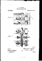
- Figure 1 is a side elevation of a portion of bracket arm projecting from a gas-holder horizontally, and guide rollers mounted thereon, and a portion of the vertical guide column.
- Fig. 2 is a section on line 00, m, Fig. 1.
- bracket arm of peculiar plate and angle-iron construction
- the same may be variously modified and constructed, without departing from the features of my invention, that shown being more or less preferred as it provides a simple and strong construction.
- arm end supporting the guiding rollers primarily consists of the vertically disposed parallel steel side plates 1.
- 5 represents a vertical guiding column, preferably of channel formation, having a tangential surface 6, and the radial surfaces 7 and 8.
- axle 9 represents a roller radially disposed relative to the holder and journaled upon the axle-rod 10, the periphery of said roller is adapted to engage and travel over the tangential surface 6 of the column.
- the axle 10 is supported upon the arm and projects through the oblong radial slots 11, formed in each of the side plates 1, forming clearance for adjusting said axle to and from the guide column 5.
- each axle 13 represents radially disposed axles, each having an intermediate boss bored to fit the axle 10, one axle 13 being 'mounted upon each end of the axle 10, and preferably outside of the bracket arm.
- the tangentially disposed rollers 14 Upon one end of each axle 13 is journaled the tangentially disposed rollers 14, their peripheries adapted to engage with and travel upon the radial surfaces 7 and 8 respectively of the column 5.
- I provide a self-contained axle structure for radially andv tangentially disposed guide rollers, with their axes angularly disposed in the same horizontalplane, providing for a uniform distribution of the strains upon the whole as a carriage.
- rollers on said axles traveling upon the guidthe same relative to the column.
- guide member consisting of a channel-iron having a main intermediate and internal bearing face at right angles to two exterior bearing faces, rollers carried by-the member to be guided engaging said bearing faces re spectively, the peripheries of said rollers lying approximately in the same plane, and means for adjusting said rollers radially relative to said guide member independently and as aunlt.
- a guide member having three bearing faces, a radial and two tangential thereto, a series of rollers in the same horizontal plane, carried by the member to be guided engaging said bearing faces respectively, and means for adjusting said rollers radially as. aunit relative to said guide member.
Landscapes
- Engineering & Computer Science (AREA)
- Mechanical Engineering (AREA)
- General Engineering & Computer Science (AREA)
- Electron Sources, Ion Sources (AREA)
Description
H. J. S TOFFBLS.
GUIDE FRAME FOR GAS HOLDERS.
APPLIOATIOH FILED MAR. 21, 1910.-
Patented Oct. 11 1910.
r. 4 Y Z lll.
v 1n: umzms PETERS c0 wAsRlNc'wN, n. c
UNITED STATES OFFICE.
HENRY JOHN STOFFELS, OF NORWOOD, OHIO, ASSIGNOR TO THE STACEY MANUFAC- TURING COMPANY, OF ELMWOOD, OHIO, A CORPORATION.
To all whom it may concern:
Be it known that I, HENRY J. STOFFELS, a subject of the German Empire, residing at Norwood, in the county of Hamilton and State of Ohio, have invented certain. new and useful Improvements in Guide-Frames for Gas-Holders, of which the following is a specification.
My invention relates to an improvement in guiding means, primarily employed in connection with the telescoping shells or sections of a gas-holder.
One of the objects of my invention is to provide the laterally extended arms of a gas-l1older with a radial roller, adapted to engage and travel upon the tangential face of a respective guide column, preferably of channel-iron form, and tangential rolls supported upon the axis of the radial roller and ada ted to engage and travel over the radial sur aces of the column.
Another object of my invention is to provide a gas-holder with guiding rollers, ada ted to travel upon a guide column, radial y and tangentially mounted relative to the holder with their axes in the same plane.
Another object of my invention is to provide a gas-holder with guiding rollers,
adapted to travel upon a guide column, radially and tangentially mounted relative to the holder, with their axes in the same plane, and means for coincidently adjusting the rollers relative to the guide column.
Further objects and features of my invention will be more fully set forth in the description of the accompanying drawings, forming a part of this speclfication, in Which:-
Figure 1 is a side elevation of a portion of bracket arm projecting from a gas-holder horizontally, and guide rollers mounted thereon, and a portion of the vertical guide column. Fig. 2 is a section on line 00, m, Fig. 1.
In the drawings, I have omitted the illustration of a complete gas-holder equipment, comprising principally a holder formed of a series of shells or sections telescopically engaging with each other, provided with hook ends, adapted to intermesh respectively with each other as the sections or shells are being raised in fillin the holder, with each section provided with a series of projecting arms or brackets extended from the periphe Specification of Letters Patent.
Application filed March 21, 1910.
Patented Oct. 11, 1910.
Serial No. 550,777.
cry of each section and traveling and engaging upon respective vertical guiding columns, the general construct-ion of which is old and well-known in the art. Therefore, in the drawings, I have only illustrated a portion of one of the horizontally projecting arms or brackets fixed to one section of a holder and a section of a guide column.
While I have illustrated the bracket arm of peculiar plate and angle-iron construction, it is obvious, however, that the same may be variously modified and constructed, without departing from the features of my invention, that shown being more or less preferred as it provides a simple and strong construction.
The construction of arm end supporting the guiding rollers primarily consists of the vertically disposed parallel steel side plates 1.
2 represents angle-irons secured along the top and bottom edge of the outside face of the side plates 1.
'3, 4, represents respectively top and bottom connecting plates secured to the angle irons 2, thereby producing a rectangular formation of arm end.
5 represents a vertical guiding column, preferably of channel formation, having a tangential surface 6, and the radial surfaces 7 and 8.
9 represents a roller radially disposed relative to the holder and journaled upon the axle-rod 10, the periphery of said roller is adapted to engage and travel over the tangential surface 6 of the column. The axle 10 is supported upon the arm and projects through the oblong radial slots 11, formed in each of the side plates 1, forming clearance for adjusting said axle to and from the guide column 5.
12 represents reinforcing plates riveted to the side plates 1, likewise provided with an oblong slot through which the axle projects.
13 represents radially disposed axles, each having an intermediate boss bored to fit the axle 10, one axle 13 being 'mounted upon each end of the axle 10, and preferably outside of the bracket arm. Upon one end of each axle 13 is journaled the tangentially disposed rollers 14, their peripheries adapted to engage with and travel upon the radial surfaces 7 and 8 respectively of the column 5.
15 represents nuts, screw threaded upon each end of the axle 10, for maintaining the axles 13, upon the axle 10, in any adjusted position. 4
16 represents collars fixed to the axle 10 intermediate of the side plates 1, to maintain the axle and its connections'upon the arm againstlateral displacement.
17 represents angle plates, one secured to each side plate 1, each provided with an oblong slot 18, through which the rear portions of the axles 13 project, and maintained in position by means of the nuts 19, 20,
screw threaded upon the axles 18, oneupon each side of the angle irons 17. .By means of these nuts 19, 20, radial coincident adjustment of all the rollers, relative to the uide column, can be made.
By this construction, I provide a self-contained axle structure for radially andv tangentially disposed guide rollers, with their axes angularly disposed in the same horizontalplane, providing for a uniform distribution of the strains upon the whole as a carriage.
Having described my invention, I claim 1. A carriage for guiding a as-holder a bracket arm, a unitary three-f old axle or radially and tangentially journaling a series of rollers in the same horizontal plane mounted on said arm, a radially; disposed and a pair of tangentially disposed rollers journaled on said axle, and means for adjusting. said axle radially.
2. The combination of a gas-holder and guiding column, a bracket arm, an axle supported upon said arm for journaling a radially disposed roller, a radial'roller adapted to travel upon the guiding column, angularly disposed axles mounted on said axle for journaling tangentially disposed rollers,
rollers on said axles traveling upon the guidthe same relative to the column.
3. In a device of the class described, a
guide member consisting of a channel-iron having a main intermediate and internal bearing face at right angles to two exterior bearing faces, rollers carried by-the member to be guided engaging said bearing faces re spectively, the peripheries of said rollers lying approximately in the same plane, and means for adjusting said rollers radially relative to said guide member independently and as aunlt.
4. In a device of the class described, a guide member having three bearing faces, a radial and two tangential thereto, a series of rollers in the same horizontal plane, carried by the member to be guided engaging said bearing faces respectively, and means for adjusting said rollers radially as. aunit relative to said guide member.
In testimony whereof, I have hereunto set.
my hand.
HENRY JOHN STOFFELS. Witnesses:
WM. F. DUNKER,
WM; B. HILLEBRAND.
Priority Applications (1)
| Application Number | Priority Date | Filing Date | Title |
|---|---|---|---|
| US55077710A US972785A (en) | 1910-03-21 | 1910-03-21 | Guide-frame for gas-holders. |
Applications Claiming Priority (1)
| Application Number | Priority Date | Filing Date | Title |
|---|---|---|---|
| US55077710A US972785A (en) | 1910-03-21 | 1910-03-21 | Guide-frame for gas-holders. |
Publications (1)
| Publication Number | Publication Date |
|---|---|
| US972785A true US972785A (en) | 1910-10-11 |
Family
ID=3041165
Family Applications (1)
| Application Number | Title | Priority Date | Filing Date |
|---|---|---|---|
| US55077710A Expired - Lifetime US972785A (en) | 1910-03-21 | 1910-03-21 | Guide-frame for gas-holders. |
Country Status (1)
| Country | Link |
|---|---|
| US (1) | US972785A (en) |
Cited By (1)
| Publication number | Priority date | Publication date | Assignee | Title |
|---|---|---|---|---|
| US2672409A (en) * | 1945-09-10 | 1954-03-16 | Koppers Co Inc | Telescoping lift-type gasholder |
-
1910
- 1910-03-21 US US55077710A patent/US972785A/en not_active Expired - Lifetime
Cited By (1)
| Publication number | Priority date | Publication date | Assignee | Title |
|---|---|---|---|---|
| US2672409A (en) * | 1945-09-10 | 1954-03-16 | Koppers Co Inc | Telescoping lift-type gasholder |
Similar Documents
| Publication | Publication Date | Title |
|---|---|---|
| US972785A (en) | Guide-frame for gas-holders. | |
| US226101A (en) | pfautz | |
| US731675A (en) | Machine for straightening t-bars, angle-bars, &c. | |
| US127967A (en) | Improvement in extension brackets | |
| US957423A (en) | Filing-cabinet. | |
| US626513A (en) | Stand for flowers | |
| US807260A (en) | Movable support for wardrobes. | |
| US572384A (en) | smith | |
| US1041763A (en) | Log-handling device. | |
| US916818A (en) | Platform-scale. | |
| US734126A (en) | Telpher. | |
| US1089090A (en) | Guide-frame for gas-holders. | |
| US473984A (en) | Combined folding-bed case and wardrobe | |
| US513514A (en) | Wadfllnoton | |
| US1353668A (en) | Trimming and finishing mechanism | |
| US934088A (en) | Supporting mechanism for draw-cut shapers and analogous machines. | |
| GB191308136A (en) | Improvements in or relating to Folding Stands or Supports particularly Adapted for Supporting Typewriters or the like. | |
| USD41616S (en) | Design for a telephone desk-stand | |
| US1033434A (en) | Spring construction. | |
| US1169904A (en) | Sliding and folding partition and door. | |
| US685981A (en) | Rolling-mill. | |
| US917800A (en) | Surveying instrument. | |
| US394635A (en) | William ii | |
| US613436A (en) | Self-leveling table | |
| US649774A (en) | Extension-table. |