US9723255B2 - Signal switching system and set top box using same - Google Patents
Signal switching system and set top box using same Download PDFInfo
- Publication number
- US9723255B2 US9723255B2 US14/826,793 US201514826793A US9723255B2 US 9723255 B2 US9723255 B2 US 9723255B2 US 201514826793 A US201514826793 A US 201514826793A US 9723255 B2 US9723255 B2 US 9723255B2
- Authority
- US
- United States
- Prior art keywords
- connector
- comparator
- switch unit
- outputs
- signal
- Prior art date
- Legal status (The legal status is an assumption and is not a legal conclusion. Google has not performed a legal analysis and makes no representation as to the accuracy of the status listed.)
- Active
Links
Images


Classifications
-
- H—ELECTRICITY
- H04—ELECTRIC COMMUNICATION TECHNIQUE
- H04N—PICTORIAL COMMUNICATION, e.g. TELEVISION
- H04N5/00—Details of television systems
- H04N5/76—Television signal recording
- H04N5/765—Interface circuits between an apparatus for recording and another apparatus
- H04N5/775—Interface circuits between an apparatus for recording and another apparatus between a recording apparatus and a television receiver
-
- H—ELECTRICITY
- H04—ELECTRIC COMMUNICATION TECHNIQUE
- H04N—PICTORIAL COMMUNICATION, e.g. TELEVISION
- H04N21/00—Selective content distribution, e.g. interactive television or video on demand [VOD]
- H04N21/40—Client devices specifically adapted for the reception of or interaction with content, e.g. set-top-box [STB]; Operations thereof
- H04N21/43—Processing of content or additional data, e.g. demultiplexing additional data from a digital video stream; Elementary client operations, e.g. monitoring of home network or synchronising decoder's clock; Client middleware
- H04N21/436—Interfacing a local distribution network, e.g. communicating with another STB or one or more peripheral devices inside the home
- H04N21/43622—Interfacing an external recording device
-
- H—ELECTRICITY
- H04—ELECTRIC COMMUNICATION TECHNIQUE
- H04N—PICTORIAL COMMUNICATION, e.g. TELEVISION
- H04N21/00—Selective content distribution, e.g. interactive television or video on demand [VOD]
- H04N21/40—Client devices specifically adapted for the reception of or interaction with content, e.g. set-top-box [STB]; Operations thereof
- H04N21/43—Processing of content or additional data, e.g. demultiplexing additional data from a digital video stream; Elementary client operations, e.g. monitoring of home network or synchronising decoder's clock; Client middleware
- H04N21/436—Interfacing a local distribution network, e.g. communicating with another STB or one or more peripheral devices inside the home
- H04N21/4363—Adapting the video or multiplex stream to a specific local network, e.g. a IEEE 1394 or Bluetooth® network
- H04N21/43632—Adapting the video or multiplex stream to a specific local network, e.g. a IEEE 1394 or Bluetooth® network involving a wired protocol, e.g. IEEE 1394
-
- H—ELECTRICITY
- H04—ELECTRIC COMMUNICATION TECHNIQUE
- H04N—PICTORIAL COMMUNICATION, e.g. TELEVISION
- H04N5/00—Details of television systems
- H04N5/44—Receiver circuitry for the reception of television signals according to analogue transmission standards
-
- H—ELECTRICITY
- H04—ELECTRIC COMMUNICATION TECHNIQUE
- H04N—PICTORIAL COMMUNICATION, e.g. TELEVISION
- H04N21/00—Selective content distribution, e.g. interactive television or video on demand [VOD]
- H04N21/40—Client devices specifically adapted for the reception of or interaction with content, e.g. set-top-box [STB]; Operations thereof
- H04N21/41—Structure of client; Structure of client peripherals
- H04N21/4104—Peripherals receiving signals from specially adapted client devices
- H04N21/4135—Peripherals receiving signals from specially adapted client devices external recorder
Definitions
- the subject matter herein generally relates to television broadcasting systems, and particularly to a signal switching system and a set top box (STB).
- STB set top box
- Set top boxes are devices known in the art that can be connected to a television (TV) or a video playback device (a DVD players/recorder, for example).
- the set top box includes a TV SCART port and a VCR SCART port.
- the TV SCART port connects to the television to output a first signal (a living signal, for example) to the television
- the VCR SCART port connects to the video playback device to receive a second signal (a playback signal, for example) from the video playback device.
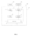
- FIG. 1 is a block diagram of a signal switching system, according to an exemplary embodiment.
- FIG. 2 is a first connection manner among the signal switching system of FIG. 1 and a television and a video playback device.
- FIG. 3 is a second connection manner among the signal switching system of FIG. 1 and the television and the video playback device.
- Coupled is defined as connected, whether directly or indirectly through intervening components, and is not necessarily limited to physical connections.
- the connection can be such that the objects are permanently connected or releasably connected.
- substantially is defined to be essentially conforming to the particular dimension, shape, or other feature that the term modifies, such that the component need not be exact.
- substantially cylindrical means that the object resembles a cylinder, but can have one or more deviations from a true cylinder.
- comprising when utilized, means “including, but not necessarily limited to”; it specifically indicates open-ended inclusion or membership in the so-described combination, group, series and the like.
- the present disclosure is described in relation to a signal switching system and a set top box.
- FIG. 1 illustrates an embodiment of a signal switching system 100 , according to an exemplary embodiment.
- the signal switching system 100 is employed in a set top box (STB) 200 , and the set top box 200 is electronically coupled between a television 300 and a video playback device 400 .
- the video playback device 400 can be a DVD players/recorder.
- the television 300 receives video programs played by the video playback device 400 via the set top box 200 .
- a live television mode the television 300 receives television programs output from the set top box 200 .
- the signal switching system 100 includes a first connector 10 , a second connector 20 , a first comparator 30 , a second comparator 40 , and a switch unit 50 .
- the first connector 10 can be a TV SCART port, and is configured to be electronically coupled to the television 300 via a first cable.
- the second connector 20 can be a VCR SCART port, and is configured to be electronically coupled to the video playback device 400 via a second cable.
- the first connector 10 includes a control pin 11 (a PIN8 of the first connector 10 , for example).
- a voltage of the control pin 11 may be greater than 5V, and when no signal is input to the first connector 10 , the voltage of the control pin 11 may be less than 0.7V.
- the second connector 20 includes a control terminal 21 (a PIN8 of the second connector 20 , for example).
- a voltage of the control terminal 21 may be greater than 5V, and when no signal is input to the second connector 20 , the voltage of the control terminal 21 may be less than 0.7V.
- the first comparator 30 is electronically coupled between the first connector 10 and the switch unit 50 , and is configured to output a control command to the switch unit 50 according to the voltage of the first connector 10 .
- the first comparator 30 has a first predetermined voltage and a second predetermined voltage. In at least one embodiment, the first predetermined voltage is 5V, and the second predetermined voltage is 0.7V. If the voltage of the first control pin 11 is less than the second predetermined voltage, the first comparator 30 outputs a low level to the switch unit 50 . If the voltage of the first control pin 11 is greater than the first predetermined voltage, the first comparator 30 outputs a high level to the switch unit 50 .
- the second comparator 40 is electronically coupled between the second connector 20 and the switch unit 50 , and is configured to output a control command to the switch unit 50 according to the voltage of the second connector 20 .
- the second comparator 40 also has the said first predetermined voltage and the said second predetermined voltage. If the voltage of the second control terminal 21 is less than the second predetermined voltage, the second comparator 40 outputs a low level to the switch unit 50 . If the voltage of the second control terminal 21 is greater than the first predetermined voltage, the second comparator 40 outputs a high level to the switch unit 50 .
- the switch unit 50 is configured to receive a first signal (a playback signal, for example) from the video playback device 400 and receive a second signal (a living signal, for example) from the set top box 200 .
- the switch unit 50 includes a first output port 52 and a second output port 54 .
- the first output port 52 is electronically coupled to the first connector 10
- the second output port 54 is electronically coupled to the second connector 20 .
- the switch unit 50 is further configured to selectively output the first signal and the second signal to the first connector 10 or the second connector 20 via the first output port 52 or the second output port 54 .
- the switch unit 50 when the switch unit 50 receives the high level output from the first comparator 30 and the low level output from the second comparator 40 , the switch unit 50 outputs the second signal via the first output port 52 or outputs the first signal via the second output port 54 .
- the switch unit 50 receives the low level output from the first comparator 30 and the high level output from the second comparator 40 , the switch unit 50 outputs the first signal via the first output port 52 or outputs the second signal via the second output port 54 .
- FIG. 2 illustrates that the television 300 is coupled to the first connector 10 via the first cable and the video playback device 400 is coupled to the second connector 20 via the second cable.
- the connection manner among the set top box 200 , the television 300 , and the video playback device 400 may be regarded as normal.
- the set top box 200 receives the first signal from the video playback device 400 .
- the voltage of the second connector 20 is greater than the first predetermined voltage to allow the second comparator 40 to output the high level to the switch unit 50
- the voltage of the first connector 10 is less than the second predetermined voltage to allow the first comparator 30 to output the low level to the switch unit 50 .
- the switch unit 50 controls the first output port 52 to output the first signal to the first connector 10 .
- the television 300 receives the first signal, and thus plays the video programs.
- the set top box 200 outputs the second signal.
- the voltage of the second connector 20 is less than the second predetermined voltage to allow the second comparator 40 to output the low level to the switch unit 50
- the voltage of the first connector 10 is greater than the first predetermined voltage to allow the first comparator 30 to output the high level to the switch unit 50 .
- the switch unit 50 controls the first output port 52 to output the second signal to the first connector 10 .
- the television 300 receives the second signal, and thus plays the television programs.
- FIG. 3 illustrates that the television 300 is coupled to the second connector 20 via the first cable and the video playback device 400 is coupled to the first connector 10 via the second cable.
- the connection manner among the set top box 200 , the television 300 , and the video playback device 400 may be regarded as abnormal.
- the set top box 200 receives the first signal from the video playback device 400 .
- the voltage of the first connector 10 is greater than the first predetermined voltage to allow the first comparator 30 to output the high level to the switch unit 50
- the voltage of the second connector 20 is less than the second predetermined voltage to allow the second comparator 40 to output the low level to the switch unit 50 .
- the switch unit 50 controls the second output port 54 to output the first signal to the second connector 20 .
- the television 300 receives the first signal, and thus plays the video programs.
- the set top box 200 outputs the second signal.
- the voltage of the second connector 20 is greater than the first predetermined voltage to allow the second comparator 40 to output the high level to the switch unit 50
- the voltage of the first connector 10 is less than the second predetermined voltage to allow the first comparator 30 to output the low level to the switch unit 50 .
- the switch unit 50 controls the second output port 54 to output the second signal to the second connector 20 .
- the television 300 receives the second signal, and thus plays the television programs.
- the first comparator 30 determines the voltage of the first connector 10
- the second comparator 40 determines the voltage of the second connector 20
- the switch unit 50 controls the first output port 52 and the second output port 54 to output the first signal or the second signal according to determination results of the first comparator 30 and the second comparator 40 .
- the television can play the television programs or the video programs even though the set top box 200 , the television 300 , and the video playback device 400 are misconnected. Therefore, the signal switching system 100 is both intelligent and convenient.
Landscapes
- Engineering & Computer Science (AREA)
- Multimedia (AREA)
- Signal Processing (AREA)
- Computer Networks & Wireless Communication (AREA)
- Controls And Circuits For Display Device (AREA)
- Two-Way Televisions, Distribution Of Moving Picture Or The Like (AREA)
Abstract
Description
Claims (12)
Applications Claiming Priority (3)
| Application Number | Priority Date | Filing Date | Title |
|---|---|---|---|
| CN201510453477.XA CN106412647B (en) | 2015-07-29 | 2015-07-29 | The set-top box of signal switching system and application the signal switching system |
| CN201510453477.X | 2015-07-29 | ||
| CN201510453477 | 2015-07-29 |
Publications (2)
| Publication Number | Publication Date |
|---|---|
| US20170034472A1 US20170034472A1 (en) | 2017-02-02 |
| US9723255B2 true US9723255B2 (en) | 2017-08-01 |
Family
ID=57883241
Family Applications (1)
| Application Number | Title | Priority Date | Filing Date |
|---|---|---|---|
| US14/826,793 Active US9723255B2 (en) | 2015-07-29 | 2015-08-14 | Signal switching system and set top box using same |
Country Status (3)
| Country | Link |
|---|---|
| US (1) | US9723255B2 (en) |
| CN (1) | CN106412647B (en) |
| TW (1) | TWI566594B (en) |
Citations (8)
| Publication number | Priority date | Publication date | Assignee | Title |
|---|---|---|---|---|
| US5631850A (en) * | 1992-09-11 | 1997-05-20 | Sony Corporation | Audio visual equipment with a digital bus system and method for initializing and confirming connection |
| US20050165967A1 (en) * | 2002-05-08 | 2005-07-28 | Koninklijke Philips Electronics N.V. | Control of an av content source component by an av content sink component |
| US20050164629A1 (en) * | 2004-01-28 | 2005-07-28 | Nec Electronics Corporation | Satellite broadcasting converter, and detector circuit used therein |
| US20060221254A1 (en) * | 2003-10-22 | 2006-10-05 | Darwin Chang | Television with automatic input switching |
| TW200640256A (en) | 2005-05-04 | 2006-11-16 | Wei-Chih Huang | Signal auto-detection module and method |
| US20080148337A1 (en) * | 2006-12-14 | 2008-06-19 | Stmicroelectronics S.A. | Video detection cell |
| US7812890B2 (en) * | 2003-05-23 | 2010-10-12 | Via Technologies, Inc. | Auto-configuration for instrument setting |
| US20120036548A1 (en) * | 2010-08-05 | 2012-02-09 | Xavier Guitton | Method for handling of audio/video signals and corresponding device |
Family Cites Families (3)
| Publication number | Priority date | Publication date | Assignee | Title |
|---|---|---|---|---|
| CN102111583A (en) * | 2009-12-24 | 2011-06-29 | 深圳市九洲电器有限公司 | Dual-syndicat des constructeurs d' appareils radiorecepteurs etteleviseurs (SCART) bypass equipment and method thereof for regulating display mode |
| CN102655574B (en) * | 2011-03-01 | 2015-11-25 | 联想(北京)有限公司 | A kind of device, the method controlling TV and television set controlling display device |
| CN104346308B (en) * | 2013-07-29 | 2018-11-20 | 鸿富锦精密工业(深圳)有限公司 | Electronic device |
-
2015
- 2015-07-29 CN CN201510453477.XA patent/CN106412647B/en active Active
- 2015-08-14 US US14/826,793 patent/US9723255B2/en active Active
- 2015-08-17 TW TW104126753A patent/TWI566594B/en active
Patent Citations (8)
| Publication number | Priority date | Publication date | Assignee | Title |
|---|---|---|---|---|
| US5631850A (en) * | 1992-09-11 | 1997-05-20 | Sony Corporation | Audio visual equipment with a digital bus system and method for initializing and confirming connection |
| US20050165967A1 (en) * | 2002-05-08 | 2005-07-28 | Koninklijke Philips Electronics N.V. | Control of an av content source component by an av content sink component |
| US7812890B2 (en) * | 2003-05-23 | 2010-10-12 | Via Technologies, Inc. | Auto-configuration for instrument setting |
| US20060221254A1 (en) * | 2003-10-22 | 2006-10-05 | Darwin Chang | Television with automatic input switching |
| US20050164629A1 (en) * | 2004-01-28 | 2005-07-28 | Nec Electronics Corporation | Satellite broadcasting converter, and detector circuit used therein |
| TW200640256A (en) | 2005-05-04 | 2006-11-16 | Wei-Chih Huang | Signal auto-detection module and method |
| US20080148337A1 (en) * | 2006-12-14 | 2008-06-19 | Stmicroelectronics S.A. | Video detection cell |
| US20120036548A1 (en) * | 2010-08-05 | 2012-02-09 | Xavier Guitton | Method for handling of audio/video signals and corresponding device |
Also Published As
| Publication number | Publication date |
|---|---|
| CN106412647A (en) | 2017-02-15 |
| TW201705769A (en) | 2017-02-01 |
| CN106412647B (en) | 2019-05-31 |
| US20170034472A1 (en) | 2017-02-02 |
| TWI566594B (en) | 2017-01-11 |
Similar Documents
| Publication | Publication Date | Title |
|---|---|---|
| US7468755B2 (en) | Video signal receiving device and video signal receiving method | |
| US8982281B2 (en) | HDMI switch system with video alerts | |
| CN103024435A (en) | HDMI (high-definition multimedia interface) interface detection device and method and HDMI interface system | |
| CN101883236B (en) | High-definition signal wireless transmission system and method | |
| US9071769B2 (en) | Method and apparatus for determining type of video signal to be output | |
| US20120242905A1 (en) | Input switching device | |
| CN104380756A (en) | Electronic apparatus, electronic apparatus system, and electronic apparatus control method | |
| MX2008015982A (en) | Analog set top calibration patterns in manufacturing. | |
| US8925020B2 (en) | Transmission system, reproduction device, transmission method, and program | |
| US20150278143A1 (en) | Method And Device For Connecting USB Port And Method For Transmitting Data | |
| US8428436B2 (en) | System and method for extended recording | |
| US9723255B2 (en) | Signal switching system and set top box using same | |
| US20070255433A1 (en) | Method and system for automatically selecting digital audio format based on sink device | |
| EP2375319A1 (en) | Audio/video apparatus and signal control method thereof | |
| MX2008015981A (en) | Generated set top calibration patterns in manufacturing. | |
| WO2017092700A1 (en) | Condition receiving method and system for intelligent operating system | |
| US20150009197A1 (en) | Video output system and load detecting method therefor | |
| US9094651B2 (en) | Method and apparatus for unified switching of digital or analog video and audio using an analog video switching device | |
| WO2017101308A1 (en) | Television signal source automatic switching equipment | |
| US7633340B2 (en) | Apparatus and method for determining the voltage level of an input signal | |
| CN108076335A (en) | A kind of projection playback equipment and its playback method, computer storage media | |
| US8059211B2 (en) | System and method for changing television channels in a video signal processor | |
| KR101437165B1 (en) | Apparatus and method for setting HDMI input output port automatically | |
| CN104811757A (en) | Method for integrating set top box play and control in intelligent digital television all-in-one machine | |
| KR100886745B1 (en) | Multimedia modulator |
Legal Events
| Date | Code | Title | Description |
|---|---|---|---|
| AS | Assignment |
Owner name: AMBIT MICROSYSTEMS (SHANGHAI) LTD., CHINA Free format text: ASSIGNMENT OF ASSIGNORS INTEREST;ASSIGNOR:CHEN, TAO;REEL/FRAME:036330/0837 Effective date: 20150811 Owner name: HON HAI PRECISION INDUSTRY CO., LTD., TAIWAN Free format text: ASSIGNMENT OF ASSIGNORS INTEREST;ASSIGNOR:CHEN, TAO;REEL/FRAME:036330/0837 Effective date: 20150811 |
|
| STCF | Information on status: patent grant |
Free format text: PATENTED CASE |
|
| AS | Assignment |
Owner name: AMBIT MICROSYSTEMS (SHANGHAI) LTD., CHINA Free format text: ASSIGNMENT OF ASSIGNORS INTEREST;ASSIGNORS:AMBIT MICROSYSTEMS (SHANGHAI) LTD.;HON HAI PRECISION INDUSTRY CO., LTD.;REEL/FRAME:045171/0409 Effective date: 20171229 |
|
| MAFP | Maintenance fee payment |
Free format text: PAYMENT OF MAINTENANCE FEE, 4TH YEAR, LARGE ENTITY (ORIGINAL EVENT CODE: M1551); ENTITY STATUS OF PATENT OWNER: LARGE ENTITY Year of fee payment: 4 |