US972301A - Reservoir-pen. - Google Patents
Reservoir-pen. Download PDFInfo
- Publication number
- US972301A US972301A US49019809A US1909490198A US972301A US 972301 A US972301 A US 972301A US 49019809 A US49019809 A US 49019809A US 1909490198 A US1909490198 A US 1909490198A US 972301 A US972301 A US 972301A
- Authority
- US
- United States
- Prior art keywords
- piston
- rod
- pen
- reservoir
- boss
- Prior art date
- Legal status (The legal status is an assumption and is not a legal conclusion. Google has not performed a legal analysis and makes no representation as to the accuracy of the status listed.)
- Expired - Lifetime
Links
- 239000007788 liquid Substances 0.000 description 3
- 230000006698 induction Effects 0.000 description 2
- 238000010276 construction Methods 0.000 description 1
- 239000004744 fabric Substances 0.000 description 1
- 230000002045 lasting effect Effects 0.000 description 1
- 230000004048 modification Effects 0.000 description 1
- 238000012986 modification Methods 0.000 description 1
Images
Classifications
-
- B—PERFORMING OPERATIONS; TRANSPORTING
- B43—WRITING OR DRAWING IMPLEMENTS; BUREAU ACCESSORIES
- B43K—IMPLEMENTS FOR WRITING OR DRAWING
- B43K5/00—Pens with ink reservoirs in holders, e.g. fountain-pens
- B43K5/02—Ink reservoirs
- B43K5/06—Ink reservoirs with movable pistons for withdrawing ink from an ink-receptacle
Definitions
- This invention has reference to reservoir pens, and more particularly to that kind of such pens in which the reservoir for containing the ink is adapted to be illed or charged by a liquid induction or forcing means within it.
- a liquid induction or forcing means within it.
- the means employed for this purpose is not lasting or durable, and others entail the diminution of liquid reservoir space in a pen of given dimensions; while in other cases, the means employed for accomplishing this object is objectionable, on the score of appearance, or for being unmechanical or unsatisfactory.
- the object of the present invention is to provide means in or in connection with such pens, which shall not have the objections hitherto existing; and in the following description of pen, the improvements hereunder are comprised.
- Vithin the pen body a that is, in the res ervoir, there is provided a piston which is adapted to be moved up and down in it; and it is so constructed as to be readily engaged by and disengaged from a rod or the like for actuating it, but which is normally detached from it; and, in the case shown in the drawings, the piston is provided with a short threaded stem c.
- the means by which this piston is operated consists of a rod or the like, which is normally detached from it, and which is provided at its lower end with an engaging means, adapted to temporarily engage with the piston Z), so that when the stopper d-shown in dotted linesdnormally fitting in the upper end of the body a, is unscrewed therefrom, and the rod end inserted,
- this piston or plunger actuating means or device is fixed on the nib inclosing cap c, and it is arranged and adapted to constitute a hook; which fits over the lappet or cloth of the waistcoat pocket in which such pens are mostly carried, or any special means for carrying it.
- This combined piston or plunger or actuating means or hook is, in some cases, extendable, as in the case shown in the drawing, and comprises two parts, which are movable in relation to each other, so as to render it relatively long when being used for actuating the plunger, and on the other hand short at other times, and when serving as only a hook.
- the extendable rod or device in the drawing consists of a stationary part g, the inner end of which is rigidly secured to the cap e, while its lower end is provided with a boss 7L, with an aperture through it.
- the re movable part is designated z', and slides in the aperture in the boss h, and is provided at its upper end with a boss j, similar to 7L,
- the two rods g and z' are rigid in relation to each other, except in the direction of their length.
- a spring 7c is provided in connection with the device, which lies parallel with the rod g; and when the rod z' is pulled out, the end of this spring 7c will come behind the boss j, 'and hold it with a degree of firmness, which, when the rod z' is engaged with the piston will enable this piston to be pressed down and pulled out.
- the top of the boss y' may be slightly tapered or inclined, so that when the boss j is forced inwardly, the lower end of the spring 7c will be pressed outward, and allow the rod z' to pass under it, and lie between it and the rod g, as shown in Fig. 2.
- the rod is provided with an internally threaded socket Z, which screws onto the threaded stud c; and after lling the reservoir a by pressing the piston b down and up by means of the actuating device, the socket Z is simply unscrewed from the pin c; and then the stopper d is screwed into the end of the body a.
- the piston Z may have a hollow short stem c on it, with a hole m through it, as shown in Fig. 3, and a slot n extending between the upper end of the stem c and the hole; and if the enlarged end of a rod such as z', slightly larger than the slot u be employed, and pressed into the hole m through the slot n, this will enable the piston to be simply moved up and down in the barrel or body a.
- any known suitable engaging and disengaging catch device can be used.
- the piston operating rod or means is constructed and arranged so as to serve not only this purpose, but also as a hook connected with the nib end inclosing or covering cap e; and it is used in the ordinary way of such pens by hooking it over the edge of a pocket or the like. Nevertheless, it may be combined with such hook, and be so formed or covered, as not to be visible, but readily available and used for the purposes referred to.
- a pen constructed as above described, for certain given dimensions will have a relatively large capacity of reservoir; or, on the other hand, it will be relatively short for a given diameter of reservoir, and will be neat, and externally present the same appearance as an ordinary reservoir pen, and will be durable, and without objectional features.
- a reservoir pen a hollow body' a, having a removable stopper d; a piston b longitudinally movable in the body and having means for detachably connecting an actuating device temporarily thereto; a cap ci: a pocket clip attached thereto; and a rod which is longitudinally slidable on the pocket clip, and can be inserted in the hollow body when the stopper is removed, and detachably connected to the piston.
- a removable stopper d having a removable stopper d; a piston b longitudinally movable in the body, and having means for detachably connecting an actuating device temporarily thereto; a cap e; and an extensible rod device, comprising a stationary part attached to the cap at 011e end and provided with an apertured boss portion at the other end; a movable part slidably mounted in the apertured boss portion, and having an apertured boss portion at one end slidably mounted on the stationary part, and means for engaging the piston at the other end; and a spring which holds the movable part in the extended position relatively to the stationary part.
- a combined pocket clip and piston actuating device for a self-filling reservoir pen comprising the combination of a rod having a longitudinally extending spring, and provided at one end with an attachment ring device, and at the other end with an apertured boss; and a second rod mounted in the apertured boss and slidable longitudinally on the rod litted with the spring, and having a slidable boss at one end engaging wit-h the spring tted rod and with which the spring engages when the rods are in the extended position, and having at the other end a pen piston engaging device.
Landscapes
- Engineering & Computer Science (AREA)
- Mechanical Engineering (AREA)
- Coating Apparatus (AREA)
- Pens And Brushes (AREA)
Description
E. M. WIDE. RESERVOIR PEN. APPLICATION FILED `APR. 15,-1909. 972,301. Patented 001. 11,1910.
ERNEST MACAULEY WADE, OF LIVERPOOL, ENGLAND.
RESERVOIR-PEN.
Specification of Letters Patent.
Application filed April 15, 1909.
Patented Oct. 11, 1910.
Serial No. 490,198.
.To all whom it may concern:
Be it known that I, ERNEST MAOAULEY VADE, a subject of the King of England, residing at 13 Hope street, Liverpool, in the county of Lancaster, England, have invented new or useful Improvements in or Connected with Reservoir-Pens, of which the following is a specification.
This invention has reference to reservoir pens, and more particularly to that kind of such pens in which the reservoir for containing the ink is adapted to be illed or charged by a liquid induction or forcing means within it. There have been a great variety of proposed means for accomplishing this object, all of which have objections in some one or other direction. In some, the means employed for this purpose is not lasting or durable, and others entail the diminution of liquid reservoir space in a pen of given dimensions; while in other cases, the means employed for accomplishing this object is objectionable, on the score of appearance, or for being unmechanical or unsatisfactory.
The object of the present invention is to provide means in or in connection with such pens, which shall not have the objections hitherto existing; and in the following description of pen, the improvements hereunder are comprised.
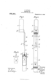
The invention will be described with the aid of the accompanying drawings, which illustrate it, in which- Figure l shows the pen in the condition in which the parts stand in relation to each other, when the liquid induction parts are being used. Fig. 2 is a view showing the same parts when not being used; and Fig. 3 shows a modification in detail.
Vithin the pen body a, that is, in the res ervoir, there is provided a piston which is adapted to be moved up and down in it; and it is so constructed as to be readily engaged by and disengaged from a rod or the like for actuating it, but which is normally detached from it; and, in the case shown in the drawings, the piston is provided with a short threaded stem c. The means by which this piston is operated, consists of a rod or the like, which is normally detached from it, and which is provided at its lower end with an engaging means, adapted to temporarily engage with the piston Z), so that when the stopper d-shown in dotted linesdnormally fitting in the upper end of the body a, is unscrewed therefrom, and the rod end inserted,
and coupled up with the piston, such piston can be pressed down toward the nib end of the pen; and if this end be inserted in an ink container, and the piston then drawn up again, the pen reservoir will become filled. And then the rod orthe like is disconnected and withdrawn, and the stopper Z is then screwed into the upper end of the body a, shown in Fig. 2. In the construction and arrangement shown in the drawings, this piston or plunger actuating means or device is fixed on the nib inclosing cap c, and it is arranged and adapted to constitute a hook; which fits over the lappet or cloth of the waistcoat pocket in which such pens are mostly carried, or any special means for carrying it. This combined piston or plunger or actuating means or hook is, in some cases, extendable, as in the case shown in the drawing, and comprises two parts, which are movable in relation to each other, so as to render it relatively long when being used for actuating the plunger, and on the other hand short at other times, and when serving as only a hook.
The extendable rod or device in the drawing consists of a stationary part g, the inner end of which is rigidly secured to the cap e, while its lower end is provided with a boss 7L, with an aperture through it. And the re movable part is designated z', and slides in the aperture in the boss h, and is provided at its upper end with a boss j, similar to 7L,
which embraces the stationary rod g. By
this means, the two rods g and z' are rigid in relation to each other, except in the direction of their length.
To hold the rod z' in its outer position, a spring 7c is provided in connection with the device, which lies parallel with the rod g; and when the rod z' is pulled out, the end of this spring 7c will come behind the boss j, 'and hold it with a degree of firmness, which, when the rod z' is engaged with the piston will enable this piston to be pressed down and pulled out. But, on the other hand, the top of the boss y' may be slightly tapered or inclined, so that when the boss j is forced inwardly, the lower end of the spring 7c will be pressed outward, and allow the rod z' to pass under it, and lie between it and the rod g, as shown in Fig. 2.
To engage the piston with this actuating device, the rod is provided with an internally threaded socket Z, which screws onto the threaded stud c; and after lling the reservoir a by pressing the piston b down and up by means of the actuating device, the socket Z is simply unscrewed from the pin c; and then the stopper d is screwed into the end of the body a.
Instead of the engaging means of the piston, and its actuating rod or device being a threaded device. of the character described, the piston Z) may have a hollow short stem c on it, with a hole m through it, as shown in Fig. 3, and a slot n extending between the upper end of the stem c and the hole; and if the enlarged end of a rod such as z', slightly larger than the slot u be employed, and pressed into the hole m through the slot n, this will enable the piston to be simply moved up and down in the barrel or body a.. Instead, however, of these means, any known suitable engaging and disengaging catch device, can be used.
In the case shown, the piston operating rod or means is constructed and arranged so as to serve not only this purpose, but also as a hook connected with the nib end inclosing or covering cap e; and it is used in the ordinary way of such pens by hooking it over the edge of a pocket or the like. Nevertheless, it may be combined with such hook, and be so formed or covered, as not to be visible, but readily available and used for the purposes referred to.
A pen constructed as above described, for certain given dimensions will have a relatively large capacity of reservoir; or, on the other hand, it will be relatively short for a given diameter of reservoir, and will be neat, and externally present the same appearance as an ordinary reservoir pen, and will be durable, and without objectional features.
What is claimed is 1. In a reservoir pen, a hollow body' a, having a removable stopper d; a piston b longitudinally movable in the body and having means for detachably connecting an actuating device temporarily thereto; a cap ci: a pocket clip attached thereto; and a rod which is longitudinally slidable on the pocket clip, and can be inserted in the hollow body when the stopper is removed, and detachably connected to the piston.
2. In a reservoir pen, a hollow body a,
having a removable stopper d; a piston b longitudinally movable in the body, and having means for detachably connecting an actuating device temporarily thereto; a cap e; and an extensible rod device, comprising a stationary part attached to the cap at 011e end and provided with an apertured boss portion at the other end; a movable part slidably mounted in the apertured boss portion, and having an apertured boss portion at one end slidably mounted on the stationary part, and means for engaging the piston at the other end; and a spring which holds the movable part in the extended position relatively to the stationary part.
8. A combined pocket clip and piston actuating device for a self-filling reservoir pen, comprising the combination of a rod having a longitudinally extending spring, and provided at one end with an attachment ring device, and at the other end with an apertured boss; and a second rod mounted in the apertured boss and slidable longitudinally on the rod litted with the spring, and having a slidable boss at one end engaging wit-h the spring tted rod and with which the spring engages when the rods are in the extended position, and having at the other end a pen piston engaging device.
In testimony whereof, I have aiixed my signature in the presence of .two witnesses.
ERNEST MACAULEY WADE.
Witnesses SoMEnviLLE GooDALL, DONALD COULTER.
Priority Applications (1)
| Application Number | Priority Date | Filing Date | Title |
|---|---|---|---|
| US49019809A US972301A (en) | 1909-04-15 | 1909-04-15 | Reservoir-pen. |
Applications Claiming Priority (1)
| Application Number | Priority Date | Filing Date | Title |
|---|---|---|---|
| US49019809A US972301A (en) | 1909-04-15 | 1909-04-15 | Reservoir-pen. |
Publications (1)
| Publication Number | Publication Date |
|---|---|
| US972301A true US972301A (en) | 1910-10-11 |
Family
ID=3040682
Family Applications (1)
| Application Number | Title | Priority Date | Filing Date |
|---|---|---|---|
| US49019809A Expired - Lifetime US972301A (en) | 1909-04-15 | 1909-04-15 | Reservoir-pen. |
Country Status (1)
| Country | Link |
|---|---|
| US (1) | US972301A (en) |
Cited By (1)
| Publication number | Priority date | Publication date | Assignee | Title |
|---|---|---|---|---|
| US2868172A (en) * | 1953-07-13 | 1959-01-13 | Kerman Ernest | Filling cap for use with valved fountain pen |
-
1909
- 1909-04-15 US US49019809A patent/US972301A/en not_active Expired - Lifetime
Cited By (1)
| Publication number | Priority date | Publication date | Assignee | Title |
|---|---|---|---|---|
| US2868172A (en) * | 1953-07-13 | 1959-01-13 | Kerman Ernest | Filling cap for use with valved fountain pen |
Similar Documents
| Publication | Publication Date | Title |
|---|---|---|
| US2642043A (en) | Fountain pen | |
| US2502866A (en) | Ball point pen | |
| US799297A (en) | Fountain-pen. | |
| US2017737A (en) | Combined writing and drawing instrument | |
| US2565601A (en) | Writing instrument | |
| US2552506A (en) | Writing instrument | |
| US589561A (en) | Fountain-pen | |
| US2143601A (en) | Fountain pen | |
| US2097266A (en) | Fountain ink marker | |
| US874738A (en) | Fountain-pen. | |
| US660823A (en) | Fountain-pen. | |
| US2734486A (en) | Aramian | |
| US1922831A (en) | Fountain pen | |
| US953438A (en) | Fountain-pen filler. | |
| US631824A (en) | Fountain-pen. | |
| US1851257A (en) | Fountain pen | |
| US717873A (en) | Self-filling fountain-pen. | |
| US1024245A (en) | Fountain-pen. | |
| US2056055A (en) | Self filling fountain pen | |
| US474356A (en) | Umbrella-locking device | |
| US1772608A (en) | Fountain pen | |
| US1602055A (en) | Self-filling stylographic pen | |
| US501895A (en) | Sixths to joseph e | |
| US1428417A (en) | Fountain pen | |
| US250937A (en) | Island |