US9717481B2 - Method of adjusting focal zone in ultrasound-guided procedures by tracking an electromagnetic sensor that implemented on a surgical device - Google Patents
Method of adjusting focal zone in ultrasound-guided procedures by tracking an electromagnetic sensor that implemented on a surgical device Download PDFInfo
- Publication number
- US9717481B2 US9717481B2 US14/761,201 US201414761201A US9717481B2 US 9717481 B2 US9717481 B2 US 9717481B2 US 201414761201 A US201414761201 A US 201414761201A US 9717481 B2 US9717481 B2 US 9717481B2
- Authority
- US
- United States
- Prior art keywords
- acoustic
- coordinate frame
- location
- image
- imaging apparatus
- Prior art date
- Legal status (The legal status is an assumption and is not a legal conclusion. Google has not performed a legal analysis and makes no representation as to the accuracy of the status listed.)
- Active
Links
Images


Classifications
-
- A—HUMAN NECESSITIES
- A61—MEDICAL OR VETERINARY SCIENCE; HYGIENE
- A61B—DIAGNOSIS; SURGERY; IDENTIFICATION
- A61B8/00—Diagnosis using ultrasonic, sonic or infrasonic waves
- A61B8/54—Control of the diagnostic device
-
- A—HUMAN NECESSITIES
- A61—MEDICAL OR VETERINARY SCIENCE; HYGIENE
- A61B—DIAGNOSIS; SURGERY; IDENTIFICATION
- A61B34/00—Computer-aided surgery; Manipulators or robots specially adapted for use in surgery
- A61B34/20—Surgical navigation systems; Devices for tracking or guiding surgical instruments, e.g. for frameless stereotaxis
-
- A—HUMAN NECESSITIES
- A61—MEDICAL OR VETERINARY SCIENCE; HYGIENE
- A61B—DIAGNOSIS; SURGERY; IDENTIFICATION
- A61B5/00—Measuring for diagnostic purposes; Identification of persons
- A61B5/06—Devices, other than using radiation, for detecting or locating foreign bodies ; determining position of probes within or on the body of the patient
- A61B5/061—Determining position of a probe within the body employing means separate from the probe, e.g. sensing internal probe position employing impedance electrodes on the surface of the body
- A61B5/062—Determining position of a probe within the body employing means separate from the probe, e.g. sensing internal probe position employing impedance electrodes on the surface of the body using magnetic field
-
- A—HUMAN NECESSITIES
- A61—MEDICAL OR VETERINARY SCIENCE; HYGIENE
- A61B—DIAGNOSIS; SURGERY; IDENTIFICATION
- A61B8/00—Diagnosis using ultrasonic, sonic or infrasonic waves
- A61B8/08—Detecting organic movements or changes, e.g. tumours, cysts, swellings
- A61B8/0833—Detecting organic movements or changes, e.g. tumours, cysts, swellings involving detecting or locating foreign bodies or organic structures
- A61B8/0841—Detecting organic movements or changes, e.g. tumours, cysts, swellings involving detecting or locating foreign bodies or organic structures for locating instruments
-
- A—HUMAN NECESSITIES
- A61—MEDICAL OR VETERINARY SCIENCE; HYGIENE
- A61B—DIAGNOSIS; SURGERY; IDENTIFICATION
- A61B8/00—Diagnosis using ultrasonic, sonic or infrasonic waves
- A61B8/46—Ultrasonic, sonic or infrasonic diagnostic devices with special arrangements for interfacing with the operator or the patient
- A61B8/461—Displaying means of special interest
-
- A—HUMAN NECESSITIES
- A61—MEDICAL OR VETERINARY SCIENCE; HYGIENE
- A61B—DIAGNOSIS; SURGERY; IDENTIFICATION
- A61B8/00—Diagnosis using ultrasonic, sonic or infrasonic waves
- A61B8/52—Devices using data or image processing specially adapted for diagnosis using ultrasonic, sonic or infrasonic waves
- A61B8/5215—Devices using data or image processing specially adapted for diagnosis using ultrasonic, sonic or infrasonic waves involving processing of medical diagnostic data
- A61B8/5238—Devices using data or image processing specially adapted for diagnosis using ultrasonic, sonic or infrasonic waves involving processing of medical diagnostic data for combining image data of patient, e.g. merging several images from different acquisition modes into one image
-
- A—HUMAN NECESSITIES
- A61—MEDICAL OR VETERINARY SCIENCE; HYGIENE
- A61B—DIAGNOSIS; SURGERY; IDENTIFICATION
- A61B34/00—Computer-aided surgery; Manipulators or robots specially adapted for use in surgery
- A61B34/20—Surgical navigation systems; Devices for tracking or guiding surgical instruments, e.g. for frameless stereotaxis
- A61B2034/2046—Tracking techniques
- A61B2034/2051—Electromagnetic tracking systems
-
- A—HUMAN NECESSITIES
- A61—MEDICAL OR VETERINARY SCIENCE; HYGIENE
- A61B—DIAGNOSIS; SURGERY; IDENTIFICATION
- A61B90/00—Instruments, implements or accessories specially adapted for surgery or diagnosis and not covered by any of the groups A61B1/00 - A61B50/00, e.g. for luxation treatment or for protecting wound edges
- A61B90/36—Image-producing devices or illumination devices not otherwise provided for
- A61B2090/364—Correlation of different images or relation of image positions in respect to the body
-
- A—HUMAN NECESSITIES
- A61—MEDICAL OR VETERINARY SCIENCE; HYGIENE
- A61B—DIAGNOSIS; SURGERY; IDENTIFICATION
- A61B90/00—Instruments, implements or accessories specially adapted for surgery or diagnosis and not covered by any of the groups A61B1/00 - A61B50/00, e.g. for luxation treatment or for protecting wound edges
- A61B90/36—Image-producing devices or illumination devices not otherwise provided for
- A61B90/37—Surgical systems with images on a monitor during operation
- A61B2090/378—Surgical systems with images on a monitor during operation using ultrasound
Definitions
- This invention pertains to an acoustic imaging system and method, and in particular to a system and method for automatic adjusting the focal zone of an acoustic imaging system during an ultrasound-guided medical procedure.
- resolution refers to the ability of an acoustic imaging apparatus to differentiate between two objects that are spatially or temporally separated from each other. It is known that acoustic image quality (or resolution) mainly depends on four factors: axial, lateral, elevation, and temporal resolutions. See, e.g., M. Peikari et al., “Effects of Ultrasound Section-Thickness on Brachytherapy Needle Tip Localization Error,” 14 TH I NTERNATIONAL C ONFERENCE ON M EDICAL I MAGE C OMPUTING AND C OMPUTER -A SSISTED I NTERVENTION (MICCAI), 2011. FIG.
- FIG. 1A illustrates the relationship between axial, lateral, and elevation directions in an acoustic imaging apparatus.
- axial resolution depends on the ability of the acoustic imaging apparatus to distinguish two objects lying at different depths, parallel to the direction of the acoustic beam.
- Axial resolution depends on the acoustic pulse length (in general, it is roughly equal to one half of the pulse length).
- lateral resolution refers to the ability of the acoustic imaging apparatus to distinguish between two objects lying beside one another and perpendicular to the acoustic beam.
- the lateral resolution depends on the distance between adjacent element beams (i.e., the beam width).
- the elevation resolution is the acoustic slice thickness.
- the temporal resolution refers to the frame rate of the acoustic imaging apparatus.
- an acoustic imaging apparatus has several scales for adjusting such image resolution parameters.
- the acoustic beam When the acoustic beam is emitted from the acoustic transducer(s), it has a narrow width, but the width is not a uniform width at all depths of the image. Instead, it converges at the point of the “focal zone,” and becomes wider as it proceeds distally.
- the focal zone is the thinnest part of the acoustic beam.
- FIG. 2 illustrates the effects of axial resolution and lateral resolution on the appearance of the cross-section of a nylon wire in an acoustic image.
- the axial resolution does not change with the image depth; however, the lateral width of the dot is directly proportional to the lateral resolution.
- a physician visually locates the current position of the needle tip (or catheter tip) on a display screen or monitor. Furthermore, a physician may visually locate the current position of the needle on a display screen or monitor when performing other medical procedures, such as biopsy procedures for the prostate and liver. The needle tip appears as bright spot in the image on the display screen. Accurate localization of the needle is a challenging problem due to existing artifacts in acoustic images. It has been shown that acoustic images may contain a number of artifacts caused by both within-plane (axial and lateral beam axes) and orthogonal-to-the-plane (elevation beam width) acoustic beam formation.
- the focal zone (narrowest part of the acoustic beam) should be adjusted to focus the zone at the exact location of the needle tip.
- a method comprises: receiving location data from an electromagnetic tracking apparatus, the location data indicating a location of an object being tracked by the electromagnetic tracking apparatus within a region of interest within biological tissue, the data indicating the location of the object with respect to an electromagnetic tracking coordinate frame employed by the electromagnetic tracking apparatus; employing a processor to transform the location data from the electromagnetic tracking coordinate frame to an acoustic image coordinate frame employed by an acoustic imaging apparatus which is configured to employ an acoustic beam to generate acoustic image data for displaying acoustic images of the region of interest, where the acoustic image coordinate frame is different from the electromagnetic tracking coordinate frame; using the transformed data to generate at least one command for the acoustic imaging apparatus to cause the acoustic imaging apparatus to adjust at least one image resolution parameter employed by the acoustic imaging apparatus to cause the acoustic images to be focused at the location of the object; and communicating the at least one command over a communication channel to the acoustic imaging apparatus.
- the surgical implement is a needle having an electromagnetic sensor disposed at the tip.
- the image resolution parameter includes at least one of the focal length and the image depth of the acoustic beam.
- the communication channel comprises an Internet connection.
- transforming the location data from the electromagnetic tracking coordinate frame to the acoustic image coordinate frame comprises using a first transform which transforms the location data from the electromagnetic tracking coordinate frame to a reference coordinate frame and a second transform which transforms the location data from the reference coordinate frame to the acoustic image coordinate frame.
- the method further comprises performing a calibration procedure to produce calibration parameters, and employing the calibration parameters to transform the location data from the electromagnetic tracking coordinate frame to the acoustic image coordinate frame.
- an apparatus comprises: an input configured to receive location data from an electromagnetic tracking apparatus, the location data indicating a location of an object being tracked by the electromagnetic tracking apparatus within a region of interest within biological tissue, the data indicating the location of the object with respect to an electromagnetic tracking coordinate frame employed by the electromagnetic tracking apparatus; a processor configured to transform the location data from the electromagnetic tracking coordinate frame to an acoustic image coordinate frame employed by an acoustic imaging apparatus which is configured to employ an acoustic beam to generate acoustic image data for displaying acoustic images of the region of interest, where the acoustic image coordinate frame is different from the electromagnetic tracking coordinate frame, and to use the transformed data to generate at least one command for the acoustic imaging apparatus to cause the acoustic imaging apparatus to adjust at least one image resolution parameter employed by the acoustic imaging apparatus to cause the acoustic images to be focused at the location of the object; and an output configured to communicate the at least one command over a communication channel to the acoustic imaging apparatus, the
- the input and the output comprise an Internet connection.
- the object is a surgical implement and the location data indicates a location of a tip of the surgical implement.
- the surgical implement is a needle having an electromagnetic sensor disposed at the tip.
- the at least image resolution parameter includes at least one of a focal length of the acoustic beam, an image depth of the acoustic beam, a time gain compensation, and a zoom window, employed by the acoustic imaging apparatus.
- the at least one image resolution parameter includes at least one of the focal length and the image depth of the acoustic beam.
- transforming the location data from the electromagnetic tracking coordinate frame to the acoustic image coordinate frame comprises using a first transform which transforms the location data from the electromagnetic tracking coordinate frame to a reference coordinate frame and a second transform which transforms the location data from the reference coordinate frame to the acoustic image coordinate frame
- a method comprises: tracking a location of an object while the object is disposed within a region of interest within biological tissue, the location of the object being determined with respect to a tracking coordinate frame; generating acoustic images of the region of interest, the acoustic images being generated with respect to an acoustic image coordinate frame which is different from the tracking coordinate frame; employing a processor to transform the location of the object from the tracking coordinate frame to the acoustic image coordinate frame; and automatically adjusting at least one image resolution parameter of the acoustic images in response to the location of the object with respect to the acoustic image coordinate frame.
- an acoustic imaging apparatus generates the acoustic images of the region of interest, and wherein automatically adjusting at least one image resolution parameter of the acoustic images in response to the location of the object comprises receiving at least one command at the acoustic imaging apparatus via a communication channel to which the acoustic imaging apparatus is connected.
- the at least one command causes the acoustic imaging apparatus to adjust at least one of a focal length, an image depth, a time gain compensation, and a zoom window, employed by the acoustic imaging apparatus.
- the communication channel employs an Ethernet protocol.
- transforming the location of the object from the tracking coordinate frame to the acoustic image coordinate frame comprises using a first transform which transforms the location data from the tracking coordinate frame to a reference coordinate frame and a second transform which transforms the location data from the reference coordinate frame to the acoustic image coordinate frame
- FIGS. 1A, 1B, 1C and 1D illustrate the concepts of axial, lateral, elevation, and temporal resolutions in an acoustic imaging apparatus.
- FIG. 2 illustrates the effects of axial resolution and lateral resolution on the appearance of the cross-section of a nylon wire in an acoustic image.
- FIG. 3 is a functional block diagram of one embodiment of an arrangement for generating acoustic images which track the location of an object within a region of interest.
- FIG. 4 shows a portion of a control panel of one embodiment of an acoustic imaging apparatus.
- FIG. 5 illustrates operating principles of one embodiment of an arrangement for generating acoustic images which includes means for tracking the location of an object within a region of interest.
- FIG. 6 illustrates operations of one embodiment of a process of generating acoustic images which track the location of an object within a region of interest.
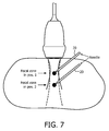
- FIG. 7 illustrates an acoustic beam tracking the location of the tip of a needle during a medical procedure.
- FIG. 8 is a flowchart of one embodiment of a method for generating acoustic images which track the location of an object within a region of interest.
- FIG. 3 is a functional block diagram of one embodiment of an arrangement 300 for generating acoustic (e.g., ultrasound) images which track the location of an object within a region of interest.
- Arrangement 300 includes an electromagnetic (EM) tracking system 310 , an acoustic (e.g., ultrasound) imaging system 320 , an acoustic probe 330 , a display device 340 , and a controller 350 .
- EM electromagnetic
- a region of interest 10 in biological tissue e.g., a human body
- an object 20 which in this particular example is a surgical implement, more specifically a needle.
- object 20 is needle 20 , but in general it should be understood that the principles to be explained below could be applied to a variety of different objects, including a variety of different surgical implements or instruments.
- Needle 20 includes an EM sensor or transducer 22 , for example disposed at a tip 21 of needle 20 .
- Controller 350 may include a processor 354 and memory 356 .
- Memory 356 may include volatile memory such as random access memory, and/or nonvolatile memory, such as read only memory and/or FLASH memory.
- memory 356 may store software or program code that is configured to cause processor 354 to execute one of more algorithms, for example various algorithms described herein, and in particular an algorithm as described below with respect to FIG. 8 .
- Controller 350 may have one or more inputs 351 and one or more outputs 352 which may be connected to one or more communication channels, such as communication channel 305 and communication channel 315 .
- an input 351 and an output 352 of controller 350 may comprise a common input/output.
- an input/output of controller 350 may comprise an Ethernet port for connecting to an Ethernet network.
- communication channel 305 and communication channel 315 may include the Internet.
- some or all of the functions of controller 350 may reside within components (e.g., a processor) of acoustic imaging system 320 or EM tracking system 310 .
- acoustic imaging system 320 and acoustic probe 330 are able to steer the direction and focal depth of the transmitted acoustic beam to a desired focal zone, which in general also becomes the focal zone for acoustic probe 330 to receive back acoustic echoes or reflections. This may be referred to hereafter as the focal zone of acoustic imaging system 320 .
- FIG. 4 shows a portion of a control panel of one embodiment of acoustic imaging system 320 .
- acoustic imaging system 320 includes a variety of manual controls for its operation.
- acoustic imaging system 320 includes a plurality of controls for manually adjusting one or more image resolution parameters employed by acoustic imaging system 320 .
- these manual controls may allow a user to manually adjust the focal zone of the acoustic beam employed by acoustic imaging system 320 , and the corresponding acoustic images displayed on display device 340 .
- these manual controls include a zoom control 322 , a focus control 324 , and a depth control 326 for adjusting the focal zone of acoustic imaging system 320 .
- acoustic imaging system 320 also includes a communication interface 321 for connection to communication channel 305 by which it acoustic imaging system 320 may receive one or more commands for controlling its operation.
- Communication interface 321 may receive one or more commands which cause it to adjust one or more image resolution parameters (e.g., the focal length of the acoustic beam, the image depth of the acoustic beam, the time gain compensation, the zoom window, etc.) which are employed by acoustic imaging system 320 .
- image resolution parameters e.g., the focal length of the acoustic beam, the image depth of the acoustic beam, the time gain compensation, the zoom window, etc.
- one or more commands may be provided to acoustic imaging system 320 over communication channel 305 via communication interface 321 to cause acoustic imaging system 320 to adjust the zoom, focus, and/or depth of the acoustic image produced by acoustic imaging system 320 .
- the one or more commands may cause acoustic imaging system to adjust the focal length and/or the image depth of the acoustic beam employed by acoustic imaging system 320 . Further details of this operation will be described below.
- acoustic imaging system 320 employs its own particular coordinate system for generating and displaying acoustic images. That is, acoustic imaging system 320 operates in three dimensions, with the three dimensions being defined by three orthogonal directions. This set of orthogonal directions is referred to here as a coordinate frame. In general, coordinates or locations within any three dimensional space may be defined with respect to an infinite number of different coordinate frames. Acoustic imaging system 320 employs its own selected coordinate frame for defining locations within area of interest 10 , and here we refer to this coordinate frame as the acoustic image coordinate frame.
- EM tracking system 310 is configured to track the location of needle 20 , and more particularly the location of EM sensor 22 at tip 21 of needle 20 , in region of interest 10 . Beneficially, EM tracking system tracks the location of needle 20 , or more specifically tip 21 of needle 20 , in real-time, as needle 20 is moved in region of interest 10 .
- EM tracking system 310 may include a display device which can show the tracked location of EM sensor 22 /needle tip 21 in real-time.
- FIG. 5 illustrates operating principles of one embodiment of an arrangement for generating acoustic images which includes means for tracking the location of an object within a region of interest.
- EM tracking system 310 is configured to track the location of needle 20 in real-time within region of interest using an electromagnetic tracking coordinate frame.
- acoustic imaging system 320 operates with an acoustic imaging coordinate frame which is different than the electromagnetic tracking coordinate frame, since in general EM tracking system 310 may operate independently from acoustic imaging system 320 .
- locations in each these two coordinate frames may be transformed to locations in a common reference coordinate frame through corresponding coordinate frame transformations.
- a second component involves converting location data for tip 21 of needle 20 obtained by EM tracking system 310 from the EM tracking coordinate frame to the acoustic imaging coordinate frame employed by acoustic imaging system 320 , so as to obtain a desired depth of focus for the acoustic beam produced by acoustic probe 330 under control of acoustic imaging system 320 .
- a third component involves generating one or more commands for acoustic imaging system 320 in a format understandable by acoustic imaging system 320 to cause acoustic imaging system 320 to adjust one or more image resolution parameters (e.g. focal length, image depth, time gain compensation, zoom window, etc.) of acoustic imaging system 320 to match the real-time location of tip 21 of the medical instrument (e.g., needle 20 ).
- image resolution parameters e.g. focal length, image depth, time gain compensation, zoom window, etc.
- the process may operate as follows.
- EM tracking system 310 tracks a location of tip 21 of needle 20 within region of interest 10 within biological tissue (e.g., a human body) in real-time. As a result, EM tracking system 310 obtains location data indicating the current location of tip 21 of needle 20 with respect to an electromagnetic tracking coordinate frame employed by electromagnetic tracking system 310 .
- EM tracking system 310 communicates the location data to controller 350 over communication channel 315 where it is received by an input of controller 350 and provided to a processor of controller 350 .
- the processor transforms the location data from the electromagnetic tracking coordinate frame to an acoustic image coordinate frame employed by acoustic imaging system 320 , where the acoustic image coordinate frame is different from the electromagnetic tracking coordinate frame.
- the processor uses the transformed data to generate one or more commands for acoustic imaging system 320 to cause acoustic imaging system 320 to adjust one or more image resolution parameters (e.g.
- acoustic imaging system 320 adjusts the one or more image resolution parameters (e.g., adjusts the focal length and/or the image depth of the acoustic beam) such that the focal zone is located at tip 21 of needle 20 .
- FIG. 7 illustrates an acoustic beam tracking the location of tip 21 of needle 20 during a medical procedure.
- acoustic imaging system 320 adjusts the acoustic beam to have its focal zone at the first position.
- acoustic imaging system 320 automatically adjusts the acoustic beam to have its focal zone at the second position.
- FIG. 8 is a flowchart of one embodiment of a method 800 for generating acoustic images which track the location of an object within a region of interest. Although in general method 800 may be executed using a variety of different equipment configurations, to provide a concrete illustration method 800 will be described with respect to arrangement 300 as illustrated in FIG. 3 .
- a calibration object is placed at one or a plurality (preferably, at least three) different locations, and for each location acoustic imaging system 320 is manually adjusted to be focused at the location of the object.
- the location data of the tracking system may then be compared with the corresponding location data for the focal zone of acoustic imaging system 320 and coordinate frame transformations may be produced for the two different coordinate frames.
- acoustic image system 320 operates with acoustic probe 330 to generate acoustic image data.
- Acoustic image may operate in conjunction with display device 340 to display produce and display acoustic images from the acoustic image data.
- the tracking system (e.g., EM tracking system 310 ) tracks the location of an object of interest, for example a medical implement such as needle 20 , within region of interest 10 in biological material in real-time.
- the tracking system may generate object location data which indicates the current location of the object with respect to the tracking coordinate frame employed by the tracking system.
- the tracking system provides the object location data to a processor, for example a processor included in controller 350 .
- the object location data is transformed from the tracking coordinate frame to the acoustic image coordinate frame.
- this transformation may comprise first transforming the location data to a reference coordinate frame, and then the location data from the reference coordinate frame to the acoustic image coordinate frame.
- the transformed object location data is employed to generate at least one command for acoustic imaging system 320 to cause acoustic imaging system 320 to adjust at least one image resolution parameter (e.g., the focal length and the image depth of the acoustic beam, time gain compensation, zoom window, etc.) employed by acoustic imaging system 320 to cause the focus of the acoustic images to match the location of the object. More specifically, one or more commands are generated to acoustic imaging system to adjust its acoustic beam to have its focal zone located at the location of the object.
- image resolution parameter e.g., the focal length and the image depth of the acoustic beam, time gain compensation, zoom window, etc.
- the command(s) are communicated via communication channel 305 to communication interface 321 of acoustic imaging system 320 .
- the command(s) exist in a format that is understood by acoustic imaging system 320 .
- the command(s) received by acoustic imaging system 320 cause acoustic imaging system 320 to adjust at least image resolution parameter, for example a parameter of its acoustic beam, to focus the acoustic images at the location of the object.
- the command(s) cause acoustic imaging system 320 to adjust the focal length and/or image depth of the acoustic beam (and thereby the acoustic images) to match the location of the object (e.g., tip 21 of needle 20 ) with respect to the acoustic image coordinate frame.
- acoustic imaging system 320 may adjust the focal zone of the acoustic beam to be located at the location of tip 21 of needle 20 .
- the process returns to operation 820 and the acoustic imaging system continues to adjust its focus to automatically track movement of the object within the region of interest in real-time and to repeatedly adjust the focus of the acoustic images to follow the movement of the object.
Priority Applications (1)
| Application Number | Priority Date | Filing Date | Title |
|---|---|---|---|
| US14/761,201 US9717481B2 (en) | 2013-01-17 | 2014-01-15 | Method of adjusting focal zone in ultrasound-guided procedures by tracking an electromagnetic sensor that implemented on a surgical device |
Applications Claiming Priority (3)
| Application Number | Priority Date | Filing Date | Title |
|---|---|---|---|
| US201361753588P | 2013-01-17 | 2013-01-17 | |
| PCT/IB2014/058281 WO2014111853A2 (en) | 2013-01-17 | 2014-01-15 | Method of adjusting focal zone in ultrasound-guided medical procedure and system employing the method |
| US14/761,201 US9717481B2 (en) | 2013-01-17 | 2014-01-15 | Method of adjusting focal zone in ultrasound-guided procedures by tracking an electromagnetic sensor that implemented on a surgical device |
Related Parent Applications (1)
| Application Number | Title | Priority Date | Filing Date |
|---|---|---|---|
| PCT/IB2014/058281 A-371-Of-International WO2014111853A2 (en) | 2013-01-17 | 2014-01-15 | Method of adjusting focal zone in ultrasound-guided medical procedure and system employing the method |
Related Child Applications (1)
| Application Number | Title | Priority Date | Filing Date |
|---|---|---|---|
| US15/642,435 Continuation US20170296153A1 (en) | 2013-01-17 | 2017-07-06 | Method of adjusting focal zone in ultrasound-guided procedures by tracking an electromagnetic sensor that implemented on a surgical device |
Publications (2)
| Publication Number | Publication Date |
|---|---|
| US20150342572A1 US20150342572A1 (en) | 2015-12-03 |
| US9717481B2 true US9717481B2 (en) | 2017-08-01 |
Family
ID=50114439
Family Applications (2)
| Application Number | Title | Priority Date | Filing Date |
|---|---|---|---|
| US14/761,201 Active US9717481B2 (en) | 2013-01-17 | 2014-01-15 | Method of adjusting focal zone in ultrasound-guided procedures by tracking an electromagnetic sensor that implemented on a surgical device |
| US15/642,435 Abandoned US20170296153A1 (en) | 2013-01-17 | 2017-07-06 | Method of adjusting focal zone in ultrasound-guided procedures by tracking an electromagnetic sensor that implemented on a surgical device |
Family Applications After (1)
| Application Number | Title | Priority Date | Filing Date |
|---|---|---|---|
| US15/642,435 Abandoned US20170296153A1 (en) | 2013-01-17 | 2017-07-06 | Method of adjusting focal zone in ultrasound-guided procedures by tracking an electromagnetic sensor that implemented on a surgical device |
Country Status (5)
| Country | Link |
|---|---|
| US (2) | US9717481B2 (de) |
| EP (1) | EP2945560B1 (de) |
| JP (1) | JP2016507288A (de) |
| CN (1) | CN104936546B (de) |
| WO (1) | WO2014111853A2 (de) |
Cited By (1)
| Publication number | Priority date | Publication date | Assignee | Title |
|---|---|---|---|---|
| US20220287779A1 (en) * | 2019-08-06 | 2022-09-15 | Koninklijke Philips N.V. | Ultrasound object zoom tracking |
Families Citing this family (7)
| Publication number | Priority date | Publication date | Assignee | Title |
|---|---|---|---|---|
| EP3108456B1 (de) * | 2014-02-19 | 2020-06-24 | Koninklijke Philips N.V. | Bewegungsangepasste visualisierung in medizinischer 4d-bildgebung |
| WO2016035370A1 (ja) * | 2014-09-02 | 2016-03-10 | オリンパス株式会社 | 超音波診断装置、超音波診断装置の作動方法 |
| EP3023059A1 (de) * | 2014-11-18 | 2016-05-25 | Samsung Medison Co., Ltd. | Ultraschallabbildungsvorrichtung und verfahren zur steuerung davon |
| EP3582693B1 (de) * | 2017-02-14 | 2021-04-07 | Koninklijke Philips N.V. | Fokusverfolgung in ultraschallsystem zur vorrichtungsverfolgung |
| EP3642646A1 (de) | 2017-06-19 | 2020-04-29 | Koninklijke Philips N.V. | Verschachtelte bildgebungs- und verfolgungssequenzen für ultraschallbasierte instrumentenverfolgung |
| CN111093512A (zh) * | 2018-04-25 | 2020-05-01 | 深圳迈瑞生物医疗电子股份有限公司 | 超声成像方法以及超声成像设备 |
| EP3968861B1 (de) * | 2019-05-17 | 2022-11-09 | Koninklijke Philips N.V. | Ultraschallsystem und verfahren zur verfolgung der bewegung eines objekts |
Citations (12)
| Publication number | Priority date | Publication date | Assignee | Title |
|---|---|---|---|---|
| US6677985B1 (en) | 1998-03-06 | 2004-01-13 | Hitachi Medical Corporation | Ultrasonic video apparatus |
| US20060193504A1 (en) * | 2003-03-27 | 2006-08-31 | Koninklijke Philips Electronics N.V. | Guidance of invasive medical devices by three dimensional ultrasonic imaging |
| US20060270934A1 (en) | 2003-03-27 | 2006-11-30 | Bernard Savord | Guidance of invasive medical devices with combined three dimensional ultrasonic imaging system |
| US20070232882A1 (en) | 2006-03-31 | 2007-10-04 | Glossop Neil D | System, Methods, and Instrumentation for Image Guided Prostate Treatment |
| EP2160978A1 (de) | 2008-09-05 | 2010-03-10 | General Electric Company | Verfahren und Vorrichtung zur Katheterführung unter Verwendung einer Kombination von Ultraschall- und Röntgenbildgebung |
| US20100081920A1 (en) | 2008-09-29 | 2010-04-01 | Civco Medical Instruments Co., Inc. | Em tracking systems for use with ultrasound and other imaging modalities |
| US20100298705A1 (en) * | 2009-05-20 | 2010-11-25 | Laurent Pelissier | Freehand ultrasound imaging systems and methods for guiding fine elongate instruments |
| WO2011107404A1 (en) * | 2010-03-03 | 2011-09-09 | Technische Universiteit Eindhoven | Needle detection in medical image data |
| WO2011138698A1 (en) * | 2010-05-03 | 2011-11-10 | Koninklijke Philips Electronics N.V. | Ultrasonic tracking of ultrasound transducer(s) aboard an interventional tool |
| WO2012018851A1 (en) | 2010-08-02 | 2012-02-09 | Joint Vue, LLC | Method and apparatus for three dimensional reconstruction of a joint using ultrasound |
| US20120203306A1 (en) * | 2005-09-10 | 2012-08-09 | Artann Laboratories, Inc. | Systems for remote generation of electrical signal in tissue based on time-reversal acoustics |
| WO2013001424A2 (en) | 2011-06-27 | 2013-01-03 | Koninklijke Philips Electronics N.V. | Ultrasound-image-guide system and volume-motion-base calibration method |
Family Cites Families (5)
| Publication number | Priority date | Publication date | Assignee | Title |
|---|---|---|---|---|
| JP4137237B2 (ja) * | 1998-03-06 | 2008-08-20 | 株式会社日立メディコ | 超音波映像装置 |
| CN102481115B (zh) * | 2009-06-05 | 2014-11-26 | 皇家飞利浦电子股份有限公司 | 用于集成式活检和治疗的系统和方法 |
| US9614686B2 (en) * | 2009-11-02 | 2017-04-04 | Time Warner Cable Enterprises Llc | Protected premises network apparatus and methods |
| WO2012024201A1 (en) * | 2010-08-19 | 2012-02-23 | Mayo Foundation For Medical Education And Research | Steerable catheter navigation with the use of interference ultrasonography |
| US20120143055A1 (en) * | 2010-12-01 | 2012-06-07 | General Electric Company | Method and system for ultrasound imaging |
-
2014
- 2014-01-15 WO PCT/IB2014/058281 patent/WO2014111853A2/en active Application Filing
- 2014-01-15 CN CN201480004708.2A patent/CN104936546B/zh active Active
- 2014-01-15 JP JP2015552192A patent/JP2016507288A/ja active Pending
- 2014-01-15 US US14/761,201 patent/US9717481B2/en active Active
- 2014-01-15 EP EP14704900.1A patent/EP2945560B1/de active Active
-
2017
- 2017-07-06 US US15/642,435 patent/US20170296153A1/en not_active Abandoned
Patent Citations (14)
| Publication number | Priority date | Publication date | Assignee | Title |
|---|---|---|---|---|
| US6677985B1 (en) | 1998-03-06 | 2004-01-13 | Hitachi Medical Corporation | Ultrasonic video apparatus |
| US20060193504A1 (en) * | 2003-03-27 | 2006-08-31 | Koninklijke Philips Electronics N.V. | Guidance of invasive medical devices by three dimensional ultrasonic imaging |
| US20060270934A1 (en) | 2003-03-27 | 2006-11-30 | Bernard Savord | Guidance of invasive medical devices with combined three dimensional ultrasonic imaging system |
| US20120203306A1 (en) * | 2005-09-10 | 2012-08-09 | Artann Laboratories, Inc. | Systems for remote generation of electrical signal in tissue based on time-reversal acoustics |
| US20070232882A1 (en) | 2006-03-31 | 2007-10-04 | Glossop Neil D | System, Methods, and Instrumentation for Image Guided Prostate Treatment |
| EP2160978A1 (de) | 2008-09-05 | 2010-03-10 | General Electric Company | Verfahren und Vorrichtung zur Katheterführung unter Verwendung einer Kombination von Ultraschall- und Röntgenbildgebung |
| US20100081920A1 (en) | 2008-09-29 | 2010-04-01 | Civco Medical Instruments Co., Inc. | Em tracking systems for use with ultrasound and other imaging modalities |
| US20100298705A1 (en) * | 2009-05-20 | 2010-11-25 | Laurent Pelissier | Freehand ultrasound imaging systems and methods for guiding fine elongate instruments |
| WO2011107404A1 (en) * | 2010-03-03 | 2011-09-09 | Technische Universiteit Eindhoven | Needle detection in medical image data |
| US20120321154A1 (en) * | 2010-03-03 | 2012-12-20 | Hendrikus Hubertus Maria Korsten | Needle detection in medical image data |
| WO2011138698A1 (en) * | 2010-05-03 | 2011-11-10 | Koninklijke Philips Electronics N.V. | Ultrasonic tracking of ultrasound transducer(s) aboard an interventional tool |
| US20130041252A1 (en) * | 2010-05-03 | 2013-02-14 | Koninklijke Philips Electronics N.V. | Ultrasonic tracking of ultrasound transducer(s) aboard an interventional tool |
| WO2012018851A1 (en) | 2010-08-02 | 2012-02-09 | Joint Vue, LLC | Method and apparatus for three dimensional reconstruction of a joint using ultrasound |
| WO2013001424A2 (en) | 2011-06-27 | 2013-01-03 | Koninklijke Philips Electronics N.V. | Ultrasound-image-guide system and volume-motion-base calibration method |
Non-Patent Citations (2)
| Title |
|---|
| Chen, Thomas Kuiran et al "A Real-Time Freehand Ultrasound Calibration System with Automatic Acuracy Feedback and Control", Ultrasound in Medicine and Biology, vol. 35, No. 1, 2009, pp. 79-93. |
| Peikari, Mohammad et al "Effects of Ultrasound Section-Thickness on Brachytherapy Needle Tip Localization Error", MICCAI 2011, Part 1, LNCS 6891, pp. 299-306. |
Cited By (1)
| Publication number | Priority date | Publication date | Assignee | Title |
|---|---|---|---|---|
| US20220287779A1 (en) * | 2019-08-06 | 2022-09-15 | Koninklijke Philips N.V. | Ultrasound object zoom tracking |
Also Published As
| Publication number | Publication date |
|---|---|
| US20170296153A1 (en) | 2017-10-19 |
| WO2014111853A3 (en) | 2014-10-30 |
| JP2016507288A (ja) | 2016-03-10 |
| WO2014111853A2 (en) | 2014-07-24 |
| US20150342572A1 (en) | 2015-12-03 |
| CN104936546A (zh) | 2015-09-23 |
| CN104936546B (zh) | 2016-09-14 |
| EP2945560A2 (de) | 2015-11-25 |
| EP2945560B1 (de) | 2016-08-17 |
Similar Documents
| Publication | Publication Date | Title |
|---|---|---|
| US9717481B2 (en) | Method of adjusting focal zone in ultrasound-guided procedures by tracking an electromagnetic sensor that implemented on a surgical device | |
| US9161741B2 (en) | Ultrasonic image processing apparatus, ultrasonic diagnostic apparatus, and ultrasonic image processing method | |
| US10342516B2 (en) | Adaptive ultrasound image optimization through automatic gain control adjustment | |
| DE112014005949T5 (de) | System zur automatischen Erkennung einer Nadelneukalibrierung | |
| US10368844B2 (en) | Automated biplane-PW workflow for ultrasonic stenosis assessment | |
| US20190200962A1 (en) | Ultrasound imaging apparatus and control method thereof | |
| RU2659021C2 (ru) | Система ультразвуковой визуализации и способ ультразвуковой визуализации | |
| JP2014028125A (ja) | 超音波診断装置及び制御プログラム | |
| CN111629671A (zh) | 超声成像设备及控制超声成像设备的方法 | |
| US11937887B2 (en) | Ultrasound system and method for tracking movement of an object | |
| RU2676521C2 (ru) | Интеграция ультразвуковой и рентгеновской модальностей | |
| US20210145403A1 (en) | Ultrasound system for enhanced instrument visualization | |
| US20200077976A1 (en) | Ultrasonic Diagnostic Device and Volume Data Acquiring Method | |
| JP7360946B2 (ja) | 装置追跡に対する超音波システムにおける焦点追跡 | |
| KR20180097270A (ko) | 초음파 진단 장치 및 그 제어 방법 | |
| US20170143301A1 (en) | Ultrasound observation apparatus | |
| JP5570955B2 (ja) | 超音波診断装置 | |
| US20230240653A1 (en) | An interventional device with an ultrasound transceiver |
Legal Events
| Date | Code | Title | Description |
|---|---|---|---|
| AS | Assignment |
Owner name: KONINKLIJKE PHILIPS N.V., NETHERLANDS Free format text: ASSIGNMENT OF ASSIGNORS INTEREST;ASSIGNORS:TAHMASEBI MARAGHOOSH, AMIR MOHAMMAD;PARTHASARATHY, VIJAY;SIGNING DATES FROM 20150714 TO 20150715;REEL/FRAME:036098/0050 |
|
| STCF | Information on status: patent grant |
Free format text: PATENTED CASE |
|
| MAFP | Maintenance fee payment |
Free format text: PAYMENT OF MAINTENANCE FEE, 4TH YEAR, LARGE ENTITY (ORIGINAL EVENT CODE: M1551); ENTITY STATUS OF PATENT OWNER: LARGE ENTITY Year of fee payment: 4 |