US9714603B2 - Dual pre-chamber combustion system - Google Patents
Dual pre-chamber combustion system Download PDFInfo
- Publication number
- US9714603B2 US9714603B2 US14/338,527 US201414338527A US9714603B2 US 9714603 B2 US9714603 B2 US 9714603B2 US 201414338527 A US201414338527 A US 201414338527A US 9714603 B2 US9714603 B2 US 9714603B2
- Authority
- US
- United States
- Prior art keywords
- cylinder bore
- fuel
- chambers
- piston
- injection
- Prior art date
- Legal status (The legal status is an assumption and is not a legal conclusion. Google has not performed a legal analysis and makes no representation as to the accuracy of the status listed.)
- Active, expires
Links
Images


Classifications
-
- F—MECHANICAL ENGINEERING; LIGHTING; HEATING; WEAPONS; BLASTING
- F02—COMBUSTION ENGINES; HOT-GAS OR COMBUSTION-PRODUCT ENGINE PLANTS
- F02B—INTERNAL-COMBUSTION PISTON ENGINES; COMBUSTION ENGINES IN GENERAL
- F02B19/00—Engines characterised by precombustion chambers
- F02B19/12—Engines characterised by precombustion chambers with positive ignition
-
- F—MECHANICAL ENGINEERING; LIGHTING; HEATING; WEAPONS; BLASTING
- F02—COMBUSTION ENGINES; HOT-GAS OR COMBUSTION-PRODUCT ENGINE PLANTS
- F02B—INTERNAL-COMBUSTION PISTON ENGINES; COMBUSTION ENGINES IN GENERAL
- F02B19/00—Engines characterised by precombustion chambers
- F02B19/10—Engines characterised by precombustion chambers with fuel introduced partly into pre-combustion chamber, and partly into cylinder
- F02B19/1004—Engines characterised by precombustion chambers with fuel introduced partly into pre-combustion chamber, and partly into cylinder details of combustion chamber, e.g. mounting arrangements
- F02B19/1009—Engines characterised by precombustion chambers with fuel introduced partly into pre-combustion chamber, and partly into cylinder details of combustion chamber, e.g. mounting arrangements heating, cooling
-
- F—MECHANICAL ENGINEERING; LIGHTING; HEATING; WEAPONS; BLASTING
- F02—COMBUSTION ENGINES; HOT-GAS OR COMBUSTION-PRODUCT ENGINE PLANTS
- F02B—INTERNAL-COMBUSTION PISTON ENGINES; COMBUSTION ENGINES IN GENERAL
- F02B19/00—Engines characterised by precombustion chambers
- F02B19/10—Engines characterised by precombustion chambers with fuel introduced partly into pre-combustion chamber, and partly into cylinder
- F02B19/1095—Engines characterised by precombustion chambers with fuel introduced partly into pre-combustion chamber, and partly into cylinder with more than one pre-combustion chamber (a stepped form of the main combustion chamber above the piston is to be considered as a pre-combustion chamber if this stepped portion is not a squish area)
-
- F—MECHANICAL ENGINEERING; LIGHTING; HEATING; WEAPONS; BLASTING
- F02—COMBUSTION ENGINES; HOT-GAS OR COMBUSTION-PRODUCT ENGINE PLANTS
- F02B—INTERNAL-COMBUSTION PISTON ENGINES; COMBUSTION ENGINES IN GENERAL
- F02B19/00—Engines characterised by precombustion chambers
- F02B19/16—Chamber shapes or constructions not specific to sub-groups F02B19/02 - F02B19/10
-
- F—MECHANICAL ENGINEERING; LIGHTING; HEATING; WEAPONS; BLASTING
- F02—COMBUSTION ENGINES; HOT-GAS OR COMBUSTION-PRODUCT ENGINE PLANTS
- F02B—INTERNAL-COMBUSTION PISTON ENGINES; COMBUSTION ENGINES IN GENERAL
- F02B23/00—Other engines characterised by special shape or construction of combustion chambers to improve operation
- F02B23/08—Other engines characterised by special shape or construction of combustion chambers to improve operation with positive ignition
- F02B23/10—Other engines characterised by special shape or construction of combustion chambers to improve operation with positive ignition with separate admission of air and fuel into cylinder
- F02B23/101—Other engines characterised by special shape or construction of combustion chambers to improve operation with positive ignition with separate admission of air and fuel into cylinder the injector being placed on or close to the cylinder centre axis, e.g. with mixture formation using spray guided concepts
-
- F—MECHANICAL ENGINEERING; LIGHTING; HEATING; WEAPONS; BLASTING
- F02—COMBUSTION ENGINES; HOT-GAS OR COMBUSTION-PRODUCT ENGINE PLANTS
- F02B—INTERNAL-COMBUSTION PISTON ENGINES; COMBUSTION ENGINES IN GENERAL
- F02B1/00—Engines characterised by fuel-air mixture compression
- F02B1/02—Engines characterised by fuel-air mixture compression with positive ignition
- F02B1/04—Engines characterised by fuel-air mixture compression with positive ignition with fuel-air mixture admission into cylinder
-
- F—MECHANICAL ENGINEERING; LIGHTING; HEATING; WEAPONS; BLASTING
- F02—COMBUSTION ENGINES; HOT-GAS OR COMBUSTION-PRODUCT ENGINE PLANTS
- F02B—INTERNAL-COMBUSTION PISTON ENGINES; COMBUSTION ENGINES IN GENERAL
- F02B19/00—Engines characterised by precombustion chambers
- F02B19/02—Engines characterised by precombustion chambers the chamber being periodically isolated from its cylinder
-
- F—MECHANICAL ENGINEERING; LIGHTING; HEATING; WEAPONS; BLASTING
- F02—COMBUSTION ENGINES; HOT-GAS OR COMBUSTION-PRODUCT ENGINE PLANTS
- F02B—INTERNAL-COMBUSTION PISTON ENGINES; COMBUSTION ENGINES IN GENERAL
- F02B19/00—Engines characterised by precombustion chambers
- F02B19/10—Engines characterised by precombustion chambers with fuel introduced partly into pre-combustion chamber, and partly into cylinder
- F02B19/1004—Engines characterised by precombustion chambers with fuel introduced partly into pre-combustion chamber, and partly into cylinder details of combustion chamber, e.g. mounting arrangements
- F02B19/1014—Engines characterised by precombustion chambers with fuel introduced partly into pre-combustion chamber, and partly into cylinder details of combustion chamber, e.g. mounting arrangements design parameters, e.g. volume, torch passage cross sectional area, length, orientation, or the like
-
- F—MECHANICAL ENGINEERING; LIGHTING; HEATING; WEAPONS; BLASTING
- F02—COMBUSTION ENGINES; HOT-GAS OR COMBUSTION-PRODUCT ENGINE PLANTS
- F02B—INTERNAL-COMBUSTION PISTON ENGINES; COMBUSTION ENGINES IN GENERAL
- F02B19/00—Engines characterised by precombustion chambers
- F02B19/14—Engines characterised by precombustion chambers with compression ignition
-
- F—MECHANICAL ENGINEERING; LIGHTING; HEATING; WEAPONS; BLASTING
- F02—COMBUSTION ENGINES; HOT-GAS OR COMBUSTION-PRODUCT ENGINE PLANTS
- F02B—INTERNAL-COMBUSTION PISTON ENGINES; COMBUSTION ENGINES IN GENERAL
- F02B3/00—Engines characterised by air compression and subsequent fuel addition
- F02B3/06—Engines characterised by air compression and subsequent fuel addition with compression ignition
-
- Y—GENERAL TAGGING OF NEW TECHNOLOGICAL DEVELOPMENTS; GENERAL TAGGING OF CROSS-SECTIONAL TECHNOLOGIES SPANNING OVER SEVERAL SECTIONS OF THE IPC; TECHNICAL SUBJECTS COVERED BY FORMER USPC CROSS-REFERENCE ART COLLECTIONS [XRACs] AND DIGESTS
- Y02—TECHNOLOGIES OR APPLICATIONS FOR MITIGATION OR ADAPTATION AGAINST CLIMATE CHANGE
- Y02T—CLIMATE CHANGE MITIGATION TECHNOLOGIES RELATED TO TRANSPORTATION
- Y02T10/00—Road transport of goods or passengers
- Y02T10/10—Internal combustion engine [ICE] based vehicles
- Y02T10/12—Improving ICE efficiencies
-
- Y02T10/125—
Definitions
- the present disclosure generally relates to a combustion system for an engine.
- a dual pre-chamber combustion system is disclosed that facilitates the use of a lean air-fuel mixture.
- NOx gasses nitrogen oxide (NOx) gasses. These types of gasses are formed when nitrogen (N2) combines with oxygen (O2) under the high temperatures associated with the combustion process, thereby forming NOx gasses such as nitric oxide (NO) and nitrogen dioxide (NO2). These gasses can have a number of adverse environmental effects when released into the atmosphere. For example, acid rain, smog, ozone layer depletion, and other adverse environmental effects have been attributed to the release of NOx gasses into the atmosphere.
- One way to reduce NOx gas production in a combustion engine is by using a sufficiently lean air-fuel mixture.
- the increased amount of air in a lean air-fuel mixture has the effect of decreasing the internal combustion temperatures of the engine, thereby lowering the formation of NOx gasses.
- the use of a lean air-fuel mixture is not without challenges. For example, running an overly lean air-fuel mixture in a traditional combustion engine can cause engine damage and “knocking,” among other issues.
- GDI gasoline direct injection
- a GDI wall guided design typically uses specialized contours on a piston to direct fuel injected from a side injector towards a centrally located spark plug.
- indirect injection designs have been used in which a fuel injector and spark plug are both located within a pre-chamber, allowing combustion to begin in the pre-chamber and spread to the primary combustion chamber.
- such approaches require complex designs and may have only marginal effects on fuel economy.
- the present invention provides systems and methods for providing combustion within an engine.
- techniques are disclosed herein that redirect fuel injected along a central axis of a cylinder bore towards pre-chambers located along the circumference of the cylinder bore.
- a combustion system for an engine includes a cylinder block that defines a cylinder bore and opposing pre-chambers located along a circumference of the cylinder bore.
- the system also includes a fuel injector located equidistant from the circumference of the cylinder bore that injects fuel in a direction perpendicular to a diameter of the cylinder bore.
- the system further includes spark plugs located within the pre-chambers that ignite at least a portion of the fuel from the fuel injector to direct ignition flames into the cylinder bore.
- the pre-chambers of the combustion system may include a plurality of apertures that direct the ignition flames into the cylinder bore.
- the apertures are each approximately one millimeter in diameter.
- the ignition flames from a particular pre-chamber may be spaced fifteen or more degrees apart.
- the cylinder block of the combustion system may define a coolant jacket that at least partially surrounds the cylinder bore.
- the combustion system may include a piston located in the cylinder bore that directs the fuel from the fuel injector towards the pre-chambers.
- the pre-chambers may be located along a circumference of the cylinder bore at locations that corresponds to a top dead center position of the piston.
- a method in which an injection of fuel is injected by a fuel injector located centrally within a cylinder bore of an engine towards a crown of a piston located within the cylinder bore. At least a portion of the injection of fuel is received at opposing pre-chambers located along a circumference of the cylinder bore. The portion of the injection of fuel is also ignited within the pre-chambers to direct ignition flames into the cylinder bore.
- the injection of fuel may be injected during a compression stroke in which the piston is moving towards a top dead center position in the cylinder bore.
- a crown of the piston may also be used to direct the injection of fuel towards the pre-chambers.
- the crown of the piston may be used to force the injection of fuel into the pre-chambers as the piston nears the top dead center position.
- the injection of fuel may be a second injection of fuel, with the method further including injecting a first injection of fuel during an intake stroke in which the piston is moving away from the fuel injector in the cylinder bore.
- the intake stroke may occur prior to the compression stroke.
- the ignition flames may be directed from a particular pre-chamber are spaced at least fifteen degrees apart. In some aspects, the ignition flames may be used from the pre-chambers to ignite at least a portion of the first injection of fuel within the cylinder bore. In a further aspect, the method may also include providing cooling to the cylinder bore using a cooling jacket that at least partially surrounds the cylinder bore.
- a combustion system for an engine in another embodiment, includes means for injecting fuel into a cylinder bore of the engine.
- the system also includes means for receiving at least a portion of the injected fuel.
- the system further includes means for igniting the received portion of the fuel to direct ignition flames into the cylinder bore.
- the combustion system may also include means for directing the injected fuel towards the receiving means, means for mixing air with the injected fuel, or means for cooling the cylinder bore.
- the systems and methods described herein provide for the use of pre-chambers that allow a lean air-fuel mixture to be used during combustion.
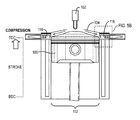
- FIG. 1 is an example side view of a dual pre-chamber combustion system
- FIG. 2 is an example top view of a cylinder block having dual pre-chambers
- FIGS. 3A-3C illustrate examples of the system of FIG. 1 during an intake stroke
- FIGS. 4A-4C illustrate examples of the system of FIG. 1 during a compression stroke
- FIGS. 5A-5C illustrate examples of the system of FIG. 1 as the piston approaches top dead center during a compression stroke
- FIGS. 6A-6C illustrate examples of the system of FIG. 1 during an ignition-power event.
- vehicle or “vehicular” or other similar term as used herein is inclusive of motor vehicles in general such as passenger automobiles including sports utility vehicles (SUV), buses, trucks, various commercial vehicles, watercraft including a variety of boats and ships, aircraft, and the like, and includes hybrid vehicles, electric vehicles, plug-in hybrid electric vehicles, hydrogen-powered vehicles and other alternative fuel vehicles (e.g., fuels derived from resources other than petroleum).
- a hybrid vehicle is a vehicle that has two or more sources of power, for example both gasoline-powered and electric-powered vehicles.
- controller refers to a hardware device that includes a memory and a processor configured to execute one or more steps that should be interpreted as its algorithmic structure.
- the memory is configured to store algorithmic steps and the processor is specifically configured to execute said algorithmic steps to perform one or more processes which are described further below.
- control logic of the present invention may be embodied as non-transitory computer readable media on a computer readable medium containing executable program instructions executed by a processor, controller or the like.
- the computer readable mediums include, but are not limited to, ROM, RAM, compact disc (CD)-ROMs, magnetic tapes, floppy disks, flash drives, smart cards and optical data storage devices.
- the computer readable recording medium can also be distributed in network coupled computer systems so that the computer readable media is stored and executed in a distributed fashion, e.g., by a telematics server or a Controller Area Network (CAN).
- a telematics server or a Controller Area Network (CAN).
- CAN Controller Area Network
- the present invention generally provides a combustion system and techniques whereby opposing pre-chambers are located along a circumference of a cylinder bore of an engine.
- a fuel injector located equidistant from the circumference injects fuel towards the center of the cylinder bore along an axis that is substantially perpendicular to the diameter of the cylinder bore.
- Combustion of the air-fuel mixture present in the chamber is initiated by igniting mixtures in the pre-chambers, thereby delivering directing ignition flames towards the mixture in the primary chamber.
- combustion system 100 includes a cylinder block 108 through which a cylinder bore 112 is formed.
- cylinder block 108 may have any number of cylinder bores that are similar to cylinder bore 112 .
- cylinder block 108 may have a total of four cylinder bores when configured for use in a four cylinder engine.
- cylinder block 108 may be formed using aluminum, an aluminum alloy, or other lightweight material.
- cylinder bore 112 may include a cylinder liner 114 that is constructed using a suitable material, such as steel, to reinforce the interior of cylinder bore 112 .
- Cylinder block 108 may include a coolant jacket 110 that at least partially encapsulates cylinder bore 112 .
- coolant jacket 110 may be a hollow structure within cylinder block 108 that surrounds the circumference of cylinder bore 112 and provides liquid cooling to it. Any suitable form of coolant may be used within coolant jacket 110 such as water, ethylene glycol, combinations thereof, etc.
- a piston 106 Located within cylinder bore 112 is a piston 106 that is driven by the combustion of an air-fuel mixture within system 100 .
- Fuel 104 used as part of the mixture is injected by a centrally located fuel injector 102 that injects fuel 104 towards the center of cylinder bore 112 .
- fuel injector 102 may be located in combustion system 100 equidistant from all points along a circumference of cylinder bore 112 and injects fuel 104 in a direction perpendicular to a diameter of cylinder bore 112 .
- Air may also be provided to cylinder bore 112 via an intake valve 130 that regulates the flow of air into cylinder bore 112 via an intake manifold 126 . After combustion, the resulting gasses are vented away from cylinder bore 112 via an exhaust valve 128 that regulates the flow of exhaust gasses to an exhaust manifold 124 .
- piston 106 is connected to a crankshaft (not shown) via a piston rod 122 and helps to rotate the crankshaft through the movement of piston 106 within cylinder bore 112 .
- piston 106 alternates between a top dead center (TDC) position (e.g., a topmost position of piston 106 within cylinder bore 112 ) and a bottom dead center (BDC) position (e.g., a bottommost position of piston 106 within cylinder bore 112 ) through the controlled operation of combustion system 100 .
- TDC top dead center
- BDC bottom dead center
- piston 106 is depicted as moving upward towards its TDC position within cylinder bore 112 .
- cylinder block 108 also defines pre-chambers 116 in which combustion of at least a portion of fuel 104 (e.g., as part of an air-fuel mixture) takes place.
- spark plugs 120 may be located within pre-chambers 116 and used to ignite a portion of the injected fuel 104 that has been mixed with air from air intake 126 .
- pre-chambers 116 are located on opposing sides of the circumference of cylinder bore 112 , as part of a dual pre-chamber configuration.
- Each of pre-chambers 116 may also include any number of orifices/apertures 118 located along cylinder bore 112 that direct the ignited air-fuel mixture towards the center of cylinder bore 112 . In other configurations, any number of pre-chambers may be located along the circumference of cylinder bore 112 at varying locations.
- FIG. 2 illustrates an example top view of the cylinder block 108 shown in FIG. 1 .
- cylinder block 108 includes four cylinder bores 112 , although any number of cylinders may be used in other embodiments.
- coolant jacket 110 formed in cylinder block 108 and at least partially encapsulates each of cylinder bores 112 .
- At the top of each cylinder bore 112 is a centrally located fuel injector 102 that injects fuel downward into the cylinder bores 112 .
- pre-chambers 116 are located on opposing sides of each of cylinder bores 112 to facilitate combustion within the bores.
- each of cylinder bores 112 may have dual, diagonally opposing pre-chambers 116 located in their upper regions.
- fuel injected downward from fuel injectors 102 is mixed with intake air and at least a portion of the air-fuel mixture is received by pre-chambers 116 , where combustion is initiated by spark plugs located within pre-chambers 116 .
- combustion system described herein follows a four stroke operation to drive the pistons of the engine.
- This operation generally includes an intake stroke, a compression stroke, a power stroke, and an exhaust stroke, which may be repeated any number of times during operation of the engine.
- FIGS. 3A-3C illustrate examples of the combustion system 100 of FIG. 1 during an intake stroke, according to one embodiment.
- piston 106 is in the process of traveling from a TDC position to a BDC position within cylinder bore 112 during the intake stroke.
- fuel injector 102 provides an injection of fuel 104 into cylinder bore 112 , which is used to form a primary air-fuel mixture within cylinder bore 112 (e.g., by mixing with air from air intake manifold 126 ).
- the primary air-fuel mixture provided during the intake stroke is a lean mixture.
- a depiction of the operation of combustion system 100 during the injection stroke is shown in chart 302 in FIG. 3C .
- the injection of fuel by fuel injector 102 is timed to coincide with the actuation of intake valve 130 (e.g., to provide air to cylinder bore 112 ), thereby filling cylinder bore 112 with the primary air-fuel mixture.
- FIGS. 4A-4C illustrate examples of the combustion system 100 of FIG. 1 during a compression stroke, according to one embodiment.
- piston 106 returns from its BDC position (e.g., after completing the intake stroke) and travels back to its TDC position during the compression stroke. This motion has a compressive effect on the primary air-fuel mixture previously injected into cylinder bore 112 during the intake stroke depicted in FIGS. 3A-3C .
- fuel injector 104 may provide another injection of fuel 104 into cylinder bore 112 as piston 106 approaches its TDC position during the compression stroke.
- fuel injector 102 may provide two separate injections of fuel 104 during any given operational cycle (e.g., during both intake and compression strokes).
- the location of piston 112 being in close proximity to pre-chambers 116 helps to direct the injected fuel 104 towards pre-chambers 116 .
- the injected fuel 104 may form inflow streams 404 along crown 132 of piston 106 during the second injection.
- crown 132 may be contoured to direct the flow of fuel 104 towards pre-chambers 116 .
- crown 132 may include grooves or other contours that facilitate the formation of fuel streams 404 towards pre-chambers 116 .
- piston 106 provides a wall guided motion during this injection to fill each of pre-chambers 116 with an air-fuel charge from the second fuel injection.
- each of pre-chambers 116 includes a plurality of apertures 118 through which fuel 104 is received.
- each of pre-chambers 116 includes three apertures 118 , although any number of apertures may be used in other embodiments.
- a depiction of the operation of combustion system 100 during the compression stroke is shown in chart 404 of FIG. 4C .
- the injection of fuel that takes place during the compression stroke may be of shorter duration than that of the injection during the intake stroke, in one embodiment. In other words, a smaller amount of fuel may be injected during the compression stroke for the purpose of directing a combustible mixture into the opposing pre-chambers 116 in cylinder bore 112 .
- FIGS. 5A-5C illustrate examples of the combustion system 100 of FIG. 1 as piston 106 approaches its TDC position during the compression stroke.
- the air-fuel charge from fuel streams 404 is compressed through apertures 118 and into pre-chambers 116 by the motion of piston 106 .
- each of apertures 118 is approximately one millimeter in diameter.
- the top ring land area of piston 106 may also clear pre-chambers 116 .
- Typical engines often have 5-8 millimeters of clearance in this region.
- a depiction of the operation of combustion system 100 during the end of the compression stroke is shown in chart 502 of FIG. 5C .
- a start of ignition (SOI) event may occur towards the end of the compression stroke, thereby leading into the power stroke.
- SOI event the spark plugs 120 located in each of pre-chambers 116 are energized leading to the ignition of the air-fuel mixtures in pre-chambers 116 and the start of the power stroke phase of operation.
- FIG. 6A-6C illustrate examples of the combustion system 100 of FIG. 1 during an ignition-power event, such as that occurring at the start of the power stroke.
- spark plugs 120 are activated during this event, thereby igniting the air-fuel mixtures within pre-chambers 116 .
- ignition flames 506 are directed back towards cylinder bore 112 .
- the direction of flames 506 back towards the center of cylinder bore 112 avoids impinging on the walls of cylinder bore 112 .
- Flames 506 operate in a jet-like manner, thereby providing a strong primary flame kernel 504 within the center of cylinder bore 112 .
- apertures 118 are formed to provide flames 506 at fifteen or more degrees of separation between each other into cylinder bore 112 .
- each of pre-chambers 116 may provide three flames 506 into cylinder bore 112 via apertures 118 as a result of igniting the air-fuel mixtures in pre-chambers 116 .
- flames 506 and the formation of flame kernel 504 have the effect of combusting the primary air-fuel mixture present within cylinder bore 112 . The energy released from this combustion drives piston 106 away from its TDC position back towards its BDC position as part of the power stroke phase of operation.
- FIG. 6C A depiction of the operation of combustion system 100 during the power stroke phase of operation is shown in chart 602 of FIG. 6C .
- the combustion of the primary air-fuel mixture within cylinder bore 112 through ignition of the mixtures in pre-chambers 116 provides power to piston 106 .
- This power is transferred to piston rod 122 which, in turn, is transferred into rotational force applied to the crankshaft of the engine.
- an exhaust stroke occurs after piston 106 reaches its BDC position within cylinder bore 112 and returns back towards its TDC position (e.g., after completion of the power stroke).
- exhaust valve 128 is actuated to allow exhaust gasses that result from the combustion to be released into exhaust manifold 124 and removed from cylinder bore 112 .
- intake valve 130 is actuated, to allow a fresh charge of air to enter cylinder bore 112 via intake manifold 126 , leading into the start of a new intake stroke phase of operation.
- the techniques described herein provide for a combustion system that supports the use of very lean air-fuel mixtures, thereby improving fuel economy and reducing the emission of NOx gasses.
- Such techniques have been shown to improve fuel economy by 5-10% over other stoichiometric combustion systems by reducing pumping losses.
- the production of NOx gasses has been shown to decrease significantly through the use of a lean air-fuel mixture.
- the techniques herein provide a simpler design than that of traditional pre-chamber systems that use both a fuel injector and spark plug within the pre-chamber itself.
Abstract
Description
Claims (14)
Priority Applications (4)
| Application Number | Priority Date | Filing Date | Title |
|---|---|---|---|
| US14/338,527 US9714603B2 (en) | 2014-07-23 | 2014-07-23 | Dual pre-chamber combustion system |
| KR1020140113838A KR101637268B1 (en) | 2014-07-23 | 2014-08-29 | Dual pre-chamber combustion system |
| CN201410548814.9A CN105275583B (en) | 2014-07-23 | 2014-10-16 | Double precombustion chamber combustion systems |
| DE102014115142.9A DE102014115142B4 (en) | 2014-07-23 | 2014-10-17 | Double antechamber combustion system |
Applications Claiming Priority (1)
| Application Number | Priority Date | Filing Date | Title |
|---|---|---|---|
| US14/338,527 US9714603B2 (en) | 2014-07-23 | 2014-07-23 | Dual pre-chamber combustion system |
Publications (2)
| Publication Number | Publication Date |
|---|---|
| US20160024994A1 US20160024994A1 (en) | 2016-01-28 |
| US9714603B2 true US9714603B2 (en) | 2017-07-25 |
Family
ID=55065323
Family Applications (1)
| Application Number | Title | Priority Date | Filing Date |
|---|---|---|---|
| US14/338,527 Active 2034-08-28 US9714603B2 (en) | 2014-07-23 | 2014-07-23 | Dual pre-chamber combustion system |
Country Status (4)
| Country | Link |
|---|---|
| US (1) | US9714603B2 (en) |
| KR (1) | KR101637268B1 (en) |
| CN (1) | CN105275583B (en) |
| DE (1) | DE102014115142B4 (en) |
Families Citing this family (23)
| Publication number | Priority date | Publication date | Assignee | Title |
|---|---|---|---|---|
| US8584648B2 (en) | 2010-11-23 | 2013-11-19 | Woodward, Inc. | Controlled spark ignited flame kernel flow |
| US9476347B2 (en) | 2010-11-23 | 2016-10-25 | Woodward, Inc. | Controlled spark ignited flame kernel flow in fuel-fed prechambers |
| US9172217B2 (en) | 2010-11-23 | 2015-10-27 | Woodward, Inc. | Pre-chamber spark plug with tubular electrode and method of manufacturing same |
| US9856848B2 (en) | 2013-01-08 | 2018-01-02 | Woodward, Inc. | Quiescent chamber hot gas igniter |
| US9765682B2 (en) | 2013-06-10 | 2017-09-19 | Woodward, Inc. | Multi-chamber igniter |
| US9653886B2 (en) | 2015-03-20 | 2017-05-16 | Woodward, Inc. | Cap shielded ignition system |
| CN107636275B (en) | 2015-03-20 | 2019-12-31 | 伍德沃德有限公司 | System and method for igniting an air-fuel mixture in an internal combustion engine |
| US20160287849A1 (en) * | 2015-03-31 | 2016-10-06 | Boston Scientific Scimed, Inc. | Vibrating self-dilation bougie |
| US9890689B2 (en) * | 2015-10-29 | 2018-02-13 | Woodward, Inc. | Gaseous fuel combustion |
| JP2017207011A (en) * | 2016-05-19 | 2017-11-24 | 日立オートモティブシステムズ株式会社 | Internal combustion engine controller |
| EP3577325B1 (en) | 2017-02-06 | 2023-10-25 | Cummins Inc. | Engine system for emission reduction without aftertreatment |
| DE102017009607A1 (en) * | 2017-10-17 | 2019-04-18 | Daimler Ag | Gas engine supply and ignition device and method of operating a gas engine supply and ignition device |
| DE102017009613A1 (en) | 2017-10-17 | 2018-04-19 | Daimler Ag | Method for operating an internal combustion engine of a motor vehicle, in particular of a motor vehicle |
| US11549429B2 (en) * | 2018-01-12 | 2023-01-10 | Transportation Ip Holdings, Llc | Engine mixing structures |
| CN112211713B (en) * | 2019-07-11 | 2021-12-21 | 曼能源解决方案公司(德国曼能源解决方案股份公司子公司) | Internal combustion engine |
| CN112211720A (en) * | 2019-07-11 | 2021-01-12 | 曼能源解决方案公司(德国曼能源解决方案股份公司子公司) | Internal combustion engine |
| DE102019123537A1 (en) * | 2019-09-03 | 2021-03-04 | Volkswagen Ag | Fuel supply system for active purging of an antechamber of an internal combustion engine operated by a gasoline engine with fuel vapor or a fuel vapor / air mixture by means of a fuel vaporizer upstream of the antechamber |
| DE202019105016U1 (en) * | 2019-09-11 | 2019-09-19 | Silvester Cambal | Fuel injection device for internal combustion engines |
| DE112021002882T5 (en) | 2020-05-20 | 2023-05-17 | Board Of Trustees Of Michigan State University | ENGINE WITH MULTIPLE FUEL INJECTORS OUTSIDE A PRE-CHAMBER |
| DK180922B1 (en) * | 2020-11-06 | 2022-06-27 | Man Energy Solutions Filial Af Man Energy Solutions Se Tyskland | Compression-ignited internal combustion engine operating on ammonia and retrofit kit |
| US11725619B2 (en) | 2021-02-23 | 2023-08-15 | Transportation Ip Holdings, Llc | Alignment system and associated method |
| US11608803B2 (en) | 2021-07-07 | 2023-03-21 | Transportation Ip Holdings, Llc | Insert device for fuel injection |
| US11781469B2 (en) | 2021-08-12 | 2023-10-10 | Transportation Ip Holdings, Llc | Insert device for fuel injection |
Citations (9)
| Publication number | Priority date | Publication date | Assignee | Title |
|---|---|---|---|---|
| US2657677A (en) * | 1948-10-06 | 1953-11-03 | Justin W Macklin | Self-ignition internal-combustion engine |
| US3955362A (en) * | 1974-08-02 | 1976-05-11 | Ford Motor Company | Exhaust heat conservation |
| JPS5422007A (en) | 1977-07-20 | 1979-02-19 | Mitsubishi Motors Corp | Internal combustion engine with precombustion chamber |
| US4566413A (en) | 1983-10-21 | 1986-01-28 | Daimler-Benz Aktiengesellschaft | Mixture-compression internal combustion engine |
| JPH0726961A (en) | 1993-07-05 | 1995-01-27 | Mazda Motor Corp | Combustion chamber structure of engine |
| JPH11324750A (en) | 1998-05-13 | 1999-11-26 | Niigata Eng Co Ltd | Combined engine and its operating method |
| JP2006161736A (en) | 2004-12-09 | 2006-06-22 | Nissan Motor Co Ltd | Prechamber type internal combustion engine |
| KR20110126873A (en) | 2010-05-18 | 2011-11-24 | 인하대학교 산학협력단 | Structure of combustion chamber for spark-ignition type internal combustion engine |
| JP2012241592A (en) | 2011-05-18 | 2012-12-10 | Mazda Motor Corp | Gasoline engine |
Family Cites Families (11)
| Publication number | Priority date | Publication date | Assignee | Title |
|---|---|---|---|---|
| DE968925C (en) * | 1937-09-09 | 1958-04-10 | Daimler Benz Ag | Internal combustion engine with early injection of light fuel, especially during the intake stroke |
| DE952042C (en) * | 1942-04-30 | 1956-11-08 | Participations Eau Soc Et | Air-compressing internal combustion engine, in particular free-flight piston engine with variable stroke |
| JPS5422008A (en) * | 1977-07-20 | 1979-02-19 | Mitsubishi Motors Corp | Internal combustion engine with precombustion |
| US5203298A (en) * | 1992-05-29 | 1993-04-20 | John Manolis | Pre-combustion chamber for internal combustion engine |
| JPH06101217A (en) * | 1992-09-18 | 1994-04-12 | Berutorii Kk | Foundation for levee body |
| JP3372399B2 (en) * | 1995-05-08 | 2003-02-04 | 三菱重工業株式会社 | Secondary combustion chamber structure of methanol engine |
| US6209511B1 (en) * | 1998-05-14 | 2001-04-03 | Niigata Engineering Co., Ltd. | Lean combustion gas engine |
| US6601560B1 (en) * | 2000-03-27 | 2003-08-05 | Avl List Gmbh | Method for starting and operating an internal combustion engine |
| JP2005264768A (en) * | 2004-03-17 | 2005-09-29 | Nissan Motor Co Ltd | Internal combustion engine |
| CN1563680A (en) * | 2004-03-31 | 2005-01-12 | 大连理工大学 | Pre-burning gasoline engine combustion system |
| FI123915B (en) * | 2008-03-03 | 2013-12-13 | Waertsilae Finland Oy | Förkammararrangemang |
-
2014
- 2014-07-23 US US14/338,527 patent/US9714603B2/en active Active
- 2014-08-29 KR KR1020140113838A patent/KR101637268B1/en active IP Right Grant
- 2014-10-16 CN CN201410548814.9A patent/CN105275583B/en active Active
- 2014-10-17 DE DE102014115142.9A patent/DE102014115142B4/en active Active
Patent Citations (9)
| Publication number | Priority date | Publication date | Assignee | Title |
|---|---|---|---|---|
| US2657677A (en) * | 1948-10-06 | 1953-11-03 | Justin W Macklin | Self-ignition internal-combustion engine |
| US3955362A (en) * | 1974-08-02 | 1976-05-11 | Ford Motor Company | Exhaust heat conservation |
| JPS5422007A (en) | 1977-07-20 | 1979-02-19 | Mitsubishi Motors Corp | Internal combustion engine with precombustion chamber |
| US4566413A (en) | 1983-10-21 | 1986-01-28 | Daimler-Benz Aktiengesellschaft | Mixture-compression internal combustion engine |
| JPH0726961A (en) | 1993-07-05 | 1995-01-27 | Mazda Motor Corp | Combustion chamber structure of engine |
| JPH11324750A (en) | 1998-05-13 | 1999-11-26 | Niigata Eng Co Ltd | Combined engine and its operating method |
| JP2006161736A (en) | 2004-12-09 | 2006-06-22 | Nissan Motor Co Ltd | Prechamber type internal combustion engine |
| KR20110126873A (en) | 2010-05-18 | 2011-11-24 | 인하대학교 산학협력단 | Structure of combustion chamber for spark-ignition type internal combustion engine |
| JP2012241592A (en) | 2011-05-18 | 2012-12-10 | Mazda Motor Corp | Gasoline engine |
Also Published As
| Publication number | Publication date |
|---|---|
| US20160024994A1 (en) | 2016-01-28 |
| KR20160012055A (en) | 2016-02-02 |
| CN105275583A (en) | 2016-01-27 |
| DE102014115142A1 (en) | 2016-01-28 |
| CN105275583B (en) | 2019-06-04 |
| DE102014115142B4 (en) | 2021-03-25 |
| KR101637268B1 (en) | 2016-07-07 |
Similar Documents
| Publication | Publication Date | Title |
|---|---|---|
| US9714603B2 (en) | Dual pre-chamber combustion system | |
| US7314036B2 (en) | Methods for operating a spark-ignition internal combustion engine | |
| US9938927B2 (en) | Piston | |
| US9599061B2 (en) | Internal combustion engine and method of igniting a fuel | |
| US9951713B2 (en) | Fuel injection apparatus | |
| US20120330534A1 (en) | Enhanced efficiency and pollutant control by multi-variable engine operation control | |
| US7150250B2 (en) | Valve and fueling strategy for operating a controlled auto-ignition four-stroke internal combustion engine | |
| JP2005256675A (en) | Method for controlling operation of internal combustion engine, device for controlling operation of internal combustion engine, and internal combustion engine | |
| US6983732B2 (en) | Injection strategy for operating a direct-injection controlled auto-ignition four-stroke internal combustion engine | |
| US10458345B2 (en) | Apparatus for controlling gasoline-diesel complex combustion engine and method for controlling gasoline-diesel complex combustion engine | |
| JP7430805B2 (en) | How to operate a motor vehicle, especially an automobile internal combustion engine | |
| US9562465B2 (en) | Dual pre-chamber piston bowl system | |
| US7004124B2 (en) | Valve strategy for operating a controlled auto-ignition four-stroke internal combustion engine | |
| JP2007162631A (en) | Control device of internal combustion engine | |
| CN104791141A (en) | Method for forming mixed gas for two-stroke LPG direct-injection engine achieving hierarchical lean combustion | |
| US11391230B2 (en) | Compression ignition engines and methods for operating the same under cold start fast idle conditions | |
| US7404390B2 (en) | Method for operating an externally ignited internal combustion engine | |
| JP6214255B2 (en) | Injector | |
| US20190101048A1 (en) | Internal-combustion engine with direct fuel injection in the direction of the intake gas motion | |
| KR101655770B1 (en) | Method of fuel injection during cold start | |
| US11828220B1 (en) | Active pre-chamber jet-assisted H2 multi-mode combustion | |
| JP3235525B2 (en) | In-cylinder injection spark ignition internal combustion engine | |
| US20140299108A1 (en) | Ic engine cylinder and piston | |
| JP2017180188A (en) | Control device of engine | |
| CN102486124A (en) | System for preventing knocking and method for controlling same |
Legal Events
| Date | Code | Title | Description |
|---|---|---|---|
| AS | Assignment |
Owner name: HYUNDAI AMERICA TECHNICAL CENTER, INC., MICHIGAN Free format text: ASSIGNMENT OF ASSIGNORS INTEREST;ASSIGNOR:ENGINEER, NAYAN;REEL/FRAME:033381/0324 Effective date: 20140716 Owner name: HYUNDAI MOTOR COMPANY, KOREA, REPUBLIC OF Free format text: ASSIGNMENT OF ASSIGNORS INTEREST;ASSIGNOR:ENGINEER, NAYAN;REEL/FRAME:033381/0324 Effective date: 20140716 Owner name: KIA MOTORS CORPORATION, KOREA, REPUBLIC OF Free format text: ASSIGNMENT OF ASSIGNORS INTEREST;ASSIGNOR:ENGINEER, NAYAN;REEL/FRAME:033381/0324 Effective date: 20140716 |
|
| STCF | Information on status: patent grant |
Free format text: PATENTED CASE |
|
| MAFP | Maintenance fee payment |
Free format text: PAYMENT OF MAINTENANCE FEE, 4TH YEAR, LARGE ENTITY (ORIGINAL EVENT CODE: M1551); ENTITY STATUS OF PATENT OWNER: LARGE ENTITY Year of fee payment: 4 |