US9689896B2 - Separating device for electronic components - Google Patents
Separating device for electronic components Download PDFInfo
- Publication number
- US9689896B2 US9689896B2 US15/003,947 US201615003947A US9689896B2 US 9689896 B2 US9689896 B2 US 9689896B2 US 201615003947 A US201615003947 A US 201615003947A US 9689896 B2 US9689896 B2 US 9689896B2
- Authority
- US
- United States
- Prior art keywords
- carrier
- separating
- carriers
- electronic components
- electronic component
- Prior art date
- Legal status (The legal status is an assumption and is not a legal conclusion. Google has not performed a legal analysis and makes no representation as to the accuracy of the status listed.)
- Active
Links
- 239000000969 carrier Substances 0.000 claims abstract description 32
- 230000006835 compression Effects 0.000 description 5
- 238000007906 compression Methods 0.000 description 5
- 230000004913 activation Effects 0.000 description 1
- 238000012986 modification Methods 0.000 description 1
- 230000004048 modification Effects 0.000 description 1
Images


Classifications
-
- G—PHYSICS
- G01—MEASURING; TESTING
- G01R—MEASURING ELECTRIC VARIABLES; MEASURING MAGNETIC VARIABLES
- G01R1/00—Details of instruments or arrangements of the types included in groups G01R5/00 - G01R13/00 and G01R31/00
- G01R1/02—General constructional details
- G01R1/04—Housings; Supporting members; Arrangements of terminals
- G01R1/0408—Test fixtures or contact fields; Connectors or connecting adaptors; Test clips; Test sockets
- G01R1/0416—Connectors, terminals
-
- H—ELECTRICITY
- H05—ELECTRIC TECHNIQUES NOT OTHERWISE PROVIDED FOR
- H05K—PRINTED CIRCUITS; CASINGS OR CONSTRUCTIONAL DETAILS OF ELECTRIC APPARATUS; MANUFACTURE OF ASSEMBLAGES OF ELECTRICAL COMPONENTS
- H05K13/00—Apparatus or processes specially adapted for manufacturing or adjusting assemblages of electric components
- H05K13/02—Feeding of components
- H05K13/021—Loading or unloading of containers
Definitions
- the disclosure relates to a separating device, more particularly to a separating device for picking up and separating a plurality of adjacent electronic components.
- An existing electronic component separating device comprises a feed mechanism and a separating mechanism.
- the feed mechanism delivers an electronic component to the separating mechanism, after which a pick-up device picks up and takes away the electronic component for subsequent testing of the electronic component.
- the separating mechanism of the existing separating device has only one carrier for carrying one electronic component at a time. Hence, there is still room for improving the separating efficiency of the existing separating device.
- an object of this disclosure is to provide a separating device for electronic components in which the separating efficiency thereof is improved.
- a separating device for electronic components comprises a base, a feed mechanism and a separating mechanism.
- the feed mechanism includes a discharge end, and is operable to convey a first electronic component and a second electronic component to the discharge end.
- the separating mechanism is disposed on the base and includes a first carrier connected slidably to the base and configured to carry the first electronic component, a second carrier connected slidably to the base and configured to carry the second electronic component, and a drive unit for driving reciprocation of the first and second carriers between a pick-up position, where the first carrier abuts against the second carrier, and a separating position, where the first and second carriers are separated from each other.
- a separating device for electronic components comprises a feed mechanism and a separating mechanism.
- the feed mechanism includes a discharge end, and is operable to convey a first electronic component and a second electronic component to the discharge end.
- the separating mechanism is configured to receive the first and second electronic components from the discharge end, and includes a first carrier configured to carry the first electronic component, a second carrier configured to carry the second electronic component, and a drive unit for driving the first and second carriers to a separating position, where the first and second carriers are separated from each other.
- the efficiency of the disclosure resides in that, through the drive unit of the separating mechanism, the first and second carriers can be driven to move between the pick-up position and the separating position.
- the feed mechanism conveys two electronic components to the abutted first and second carriers.
- the first and second carriers are separated from each other, and a pick-up device can be activated to pick-up and take away the two electronic components 4 carried by the first and second carrier seats.
- FIG. 1 is a perspective view, illustrating a separating device according to the embodiment of the disclosure cooperating with a pick-up device;
- FIG. 2 is an enlarged perspective view of the embodiment of the separating device
- FIG. 3 is a fragmentary top view for illustrating a first carrier and a second carrier of the embodiment disposed at a pick-up position;
- FIG. 4 is a view similar to FIG. 3 , but illustrating the first and second carriers being moved from the pick-up position to a separating position;
- FIG. 5 is a view similar to FIG. 3 , but illustrating the first and second carriers at the separating position
- FIG. 6 is a fragmentary schematic side view of the embodiment, illustrating the first and second carriers at the separating position
- FIG. 7 is a view similar to FIG. 6 , but illustrating two pick-up members of the pick-up device respectively picking up two electronic components carried by the first and second carriers;
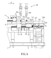
- FIG. 8 is a view similar to FIG. 7 , but illustrating the pick-up members respectively taking away the electronic components.
- a separating device 10 according to the embodiment of the disclosure is shown to cooperate with a pick-up device 20 during operation.
- the separating device 10 comprises a base 1 , a feed mechanism 2 and a separating mechanism 3 .
- the base 1 includes a base platform 11 , a first support member 12 , two second support members 13 , a carrier platform 14 , a slide rail 15 and two spring-loaded stopping members 16 .
- the base platform 11 is supported on a planar surface, such as a ground, by two spaced-apart legs 18 , and has a front end 111 and a rear end 112 opposite to the front end 111 .
- the first support member 12 is mounted on the platform 11 in proximity to the front end 111 thereof.
- the second support members 13 are mounted on the platform 11 rearwardly of the first support member 12 , and are spaced apart from each other in a front-rear direction.
- the first support member 12 has a height higher than that of each second support member 13 .
- the carrier platform 14 is mounted on and supported by top ends of the second support members 13 , and has a top surface 141 , a bottom surface 146 , two lateral surfaces 142 (only one is visible in FIG. 2 ) connected between the top and bottom surfaces 141 , 146 , two first notches 143 , and two second notches 144 .
- the first notches 143 extend downwardly from the top surface 141 , inwardly from the respective lateral surfaces 142 and terminating upwardly of the bottom surface 146 .
- the first notches 143 do not communicate with each other, and are proximate to the feed mechanism 2 .
- the second notches 144 extend downwardly from the top surface 141 , inwardly from the respective lateral surfaces 142 and terminating upwardly of the bottom surface 146 .
- the second notches 144 do not communicate with each other, and are respectively disposed spacedly rearwardly of the first notches 143 . That is, the second notches 144 are distal from the feed mechanism 2 . Moreover, the second notches 144 do not communicate with the first notches 143 .
- the carrier platform 14 is notched such that a first divider 147 and a second divider 145 are formed.
- the first divider 147 is formed between the first notches 143 and between the second notches 144 , and extends in the front-rear direction.
- the second divider 145 is formed between the first and second notches 143 , 144 , extends in a left-right direction which is transverse to the front-rear direction, and intersects the first divider 147 .
- Each of the spring-loaded stopping members 16 extends through and is disposed on the second divider 145 such that one end thereof is located in one of the first notches 143 and the other end thereof is located in a corresponding one of the second notches 144 .
- the slide rail 15 is mounted on the first divider 147 between the first notches 143 and between the second notches 144 .
- the number of the spring-loaded stopping members 16 is not limited to two, and may be one in an alternative embodiment.
- the feed mechanism 2 is mounted on and supported by the first support member 12 , and includes a discharge end 21 .
- the feed mechanism 2 is movable along a conveying direction (D), which is a front-to-rear direction, for conveying a plurality of electronic components 4 to the discharge end 21 .
- the electronic components 4 are arranged side by side along the conveying direction (D).
- the base platform 11 extends along the conveying direction (D).
- the separating mechanism 3 includes a first carrier 31 , a second carrier 32 , a pushing assembly 313 and a drive unit 33 .
- the first carrier 31 is proximate to the discharge end 21 for carrying one of the electronic components 4 , and includes a first slide block 311 and a first carrier seat 312 .
- the first slide block 311 is connected slidably to the slide rail 15 , and has a substantially inverted U-shaped body including a bight portion, left and right arms extending from left and right ends of the bight portion into the first notches 143 , respectively, a first abutment surface ( 311 a ) facing the second carrier 32 , and a second abutment surface ( 311 b ) opposite to the first abutment surface ( 311 a ) and facing the discharge end 21 .
- the first carrier seat 312 is mounted on and extends upwardly from a top surface of the bight portion of the first slide block 311 immediately adjacent to the first abutment surface ( 311 a ) for carrying the one of the electronic components 4 .
- the first carrier seat 312 has an inverted T-shaped cross section including a horizontal column 318 secured to the top surface of the bight portion of the first slide block 311 , a square-shaped vertical column 317 extending upwardly and transversely from the horizontal column 318 , and an air hole 316 extending through the horizontal and vertical columns 318 , 317 .
- the second carrier 32 is located rearwardly of the first carrier 31 and is distal from the discharge end 21 for carrying another one of the electronic components 4 .
- the second carrier 32 includes a second slide block 321 and a second carrier seat 322 .
- the second slide block 321 is connected slidably to the slide rail 15 , and has a first abutment surface ( 321 a ), and a second abutment surface ( 321 b ) opposite to the first abutment surface ( 321 a ).
- the second slide block 321 is formed with two through holes 323 that extend through the first and second abutment surfaces ( 321 a , 321 b ) and that are spaced apart from each other in the left-right direction.
- the second carrier seat 322 is mounted on and extends upwardly from a top surface of the second slide block 321 immediately adjacent to the first abutment surface ( 321 a ) for carrying the another one of the electronic components 4 , and corresponds in position to the first carrier seat 312 .
- the second carrier seat 322 has an inverted T-shaped cross section including a horizontal column 328 secured to the top surface of the second slide block 321 , a vertical column 327 extending upwardly and transversely from the horizontal column 328 , a stopping protrusion ( 322 a ) protruding from a top end of the vertical column 327 , and an air hole 325 extending through the horizontal and vertical columns 328 , 327 .
- the pushing assembly 313 includes two connecting rods 314 and two resilient members in the form of compression springs 315 .
- Each of the connecting rods 314 has one end connected to the first abutment surface ( 311 a ), and another end opposite to the one end and extending through a respective one of the through holes 323 along the conveying direction (D).
- the another end of each connecting rod 314 terminates with a flange ( 314 a ).
- Each of the compression springs 315 is sleeved on a respective one of the connecting rods 314 , and has a first end ( 315 a ) abutting against the second abutment surface ( 321 b ), and a second end ( 315 b ) opposite to the first end ( 315 a ) and abutting against the flange ( 314 a ) of the respective connecting rod 314 .
- the drive unit 33 is connected to the second slide block 321 , is proximate to the second notches 144 , and is used for driving reciprocation of the first and second carriers 31 , 32 between a pick-up position, as shown in FIG. 3 , and a separating position, as shown in FIG. 5 .
- the pick-up position the first and second carriers 31 , 32 abut against each other, and the first carrier 31 also abuts against the discharge end 21 of the feed mechanism 2 .
- the first and second carriers 31 , 32 are separated from each other, and the first carrier 31 is disposed away from the discharge end 21 .
- the discharge end 21 and the stopping members 16 are used to restrict movement of the first carrier seat 312 along the slide rail 15 within the region of the first notches 143 so as to prevent the first slide block 311 from escaping from the slide rail 15 .
- the drive unit 33 includes a driving motor 331 mounted on the base platform 11 and having a rotary shaft 334 , a rotary member 332 , and a swing lever 333 .
- the rotary member 332 has a center fixed to the rotary shaft 334 so that the rotary member 332 rotates along with the rotary shaft 334 .
- the rotary member 332 has a shaft portion ( 332 a ) spaced apart from and parallel to the rotary shaft 334 .
- the swing lever 333 has two opposite ends rotatably pivoted to the shaft portion ( 332 a ) and a shaft portion 324 of the second slide block 321 , respectively.
- the first carrier seat 312 abuts against the discharge end 21 (see FIG. 2 ) of the feed mechanism 2
- the second carrier seat 322 abuts against the first carrier seat 312 . That is, the second abutment surface ( 311 b ) (see FIG. 2 ) of the first slide block 311 abuts against the discharge end 21 , and the first abutment surface ( 321 a ) of the second slide block 321 abuts against the first abutment surface ( 311 a ) of the first slide block 311 .
- the spring-loaded stopping members 16 and the compression springs 315 are all in an uncompressed state, and the shaft portion ( 332 a ) of the rotary member 332 is disposed forwardly of the rotary shaft 334 .
- the feed mechanism 2 is operated to move along the conveying direction (D) and push two electronic components 4 to the abutted first and second carrier seats 312 , 322 .
- the stopping protrusion ( 322 a ) of the second carrier seat 322 that blocks a leading one of the electronic components 4 from further movement along the conveying direction (D)
- two electronic components 4 can be accurately and respectively disposed on the first and second carrier seats 312 , 322 .
- the air holes 316 , 325 of the first and second carrier seats 312 , 322 are vacuumed to suck the respective electronic components 4 , thereby stably positioning the two electronic components 4 on the respective first and second carrier seats 312 , 322 .
- the driving motor 331 is then activated to drive the shaft portion ( 332 a ) of the rotary member 332 to rotate along an arrow in a clockwise direction.
- the shaft portion ( 332 a ) drives the swing lever 333 to rotate therealong, and the second slide block 321 is pulled by the swing lever 333 to gradually move away from the first slide block 311 along the conveying direction (D) so as to separate the first and second slide blocks 311 , 321 .
- the second slide block 321 is also continuously pulled by the swing lever 333 to move along the conveying direction (D) until the second abutment surface ( 321 b ) of the second slide block 321 presses the compression springs 315 against the respective flanges ( 314 a ) of the connecting rods 314 .
- the second ends ( 315 b ) of the compression springs 315 will push the flanges ( 314 a ) of the connecting rods 314 to move the connecting rods 314 and the first carrier 31 away from the discharge end 21 along the conveying direction (D).
- the first abutment surface ( 311 a ) of the first carrier 31 pushes and compresses the spring-loaded stopping members 16
- the first carrier is stopped by the stopping members 16 from continuously moving along the conveying direction (D).
- the swing lever 333 will continue to drive movement of the second slide block 321 along the conveying direction (D) so as to widen the distance between the first and second carriers 31 , 32 .
- the driving motor 331 stops driving the rotation of the rotary member 332 .
- the first and second carriers 31 , 32 are disposed at the separating position, and air is filled into the air holes 316 , 325 of the first and second carrier seats 312 , 322 , so that the electronic components 4 are no longer sucked by the first and second carrier seats 312 , 322 .
- two pick-up members 201 of the pick-up device 20 are operated to respectively align first with the electronic components 4 carried by the first and second carrier seats 312 , 322 , after which they are moved down simultaneously and synchronously to pick-up and take away the electronic components 4 .
- the structure of each of the pick-up members 201 is similar to that of each of the first and second carrier seats 312 , 322 , and uses the same means to suck and pick-up the respective electronic component 4 . Since the means for sucking the electronic components 4 by the first and second carrier seats 312 , 322 and the pick-up members 201 is conventional and is well known in the art, a detailed description thereof is dispensed with herein.
- the driving motor 331 is reactivated to drive the shaft portion ( 332 a ) of the rotary member 332 to rotate clockwise so as to move the first and second carriers 31 , 32 back to the pick-up position, so that the first and second carriers 31 , 32 can continue to carry another two of the electronic components 4 for the separating operation.
- the first and second carriers 31 , 32 can be driven to move between the pick-up position and the separating position.
- the feed mechanism 2 conveys two electronic components 4 to the abutted first and second carriers 31 , 32 .
- the shaft portion ( 332 a ) of the rotary member 332 is driven to rotate along with the rotary shaft 334 .
- the shaft portion ( 332 a ) rotates, it drives the swing lever 333 to rotate therealong so that the swing lever 333 can pull and move the first and second carriers 31 , to the separating position.
- the first and second carriers 31 , 32 are separated from each other, and the pick-up members 201 of the pick-up device 20 are activated to pick-up and take away the two electronic components 4 carried by the first and second carrier seats 312 , 322 .
- the effect of separating and taking away two electronic components 4 at one time can thus be achieved. Therefore, the object of this disclosure can be realized.
Landscapes
- Engineering & Computer Science (AREA)
- Manufacturing & Machinery (AREA)
- Microelectronics & Electronic Packaging (AREA)
- Physics & Mathematics (AREA)
- General Physics & Mathematics (AREA)
- Automatic Assembly (AREA)
- Branching, Merging, And Special Transfer Between Conveyors (AREA)
- Mechanical Engineering (AREA)
- Supply And Installment Of Electrical Components (AREA)
- Special Conveying (AREA)
Abstract
Description
Claims (6)
Applications Claiming Priority (3)
| Application Number | Priority Date | Filing Date | Title |
|---|---|---|---|
| TW104206604 | 2015-04-30 | ||
| TW104206604U | 2015-04-30 | ||
| TW104206604 | 2015-04-30 |
Publications (2)
| Publication Number | Publication Date |
|---|---|
| US20160318717A1 US20160318717A1 (en) | 2016-11-03 |
| US9689896B2 true US9689896B2 (en) | 2017-06-27 |
Family
ID=57205632
Family Applications (1)
| Application Number | Title | Priority Date | Filing Date |
|---|---|---|---|
| US15/003,947 Active US9689896B2 (en) | 2015-04-30 | 2016-01-22 | Separating device for electronic components |
Country Status (2)
| Country | Link |
|---|---|
| US (1) | US9689896B2 (en) |
| TW (1) | TWI595933B (en) |
Families Citing this family (3)
| Publication number | Priority date | Publication date | Assignee | Title |
|---|---|---|---|---|
| DE102017124571B4 (en) | 2017-10-20 | 2020-01-09 | Asm Assembly Systems Gmbh & Co. Kg | Holding and drive device, tool device, supplementary tool device from a modular component handling device, device for handling components and method for application-specific configuration of such a device |
| TWI631651B (en) * | 2017-10-20 | 2018-08-01 | 鴻勁精密股份有限公司 | Conveying device with bearing unit and test classification device thereof |
| CN108562583A (en) * | 2018-05-07 | 2018-09-21 | 研祥智能科技股份有限公司 | Signal docking facilities, vision detection system and its visible detection method |
Citations (3)
| Publication number | Priority date | Publication date | Assignee | Title |
|---|---|---|---|---|
| US6409453B1 (en) * | 1998-02-18 | 2002-06-25 | Applied Materials, Inc. | End effector for wafer handler in processing system |
| US20100080675A1 (en) * | 2008-09-29 | 2010-04-01 | Monteiro Luciano Trindade De Sousa | Transfer module for transferring parts between work stations |
| US20130230375A1 (en) * | 2012-03-01 | 2013-09-05 | Taiwan Semiconductor Manufacturing Co., Ltd. | Automated material handling system and method for semiconductor manufacturing |
Family Cites Families (1)
| Publication number | Priority date | Publication date | Assignee | Title |
|---|---|---|---|---|
| TWM426867U (en) * | 2011-12-06 | 2012-04-11 | Daho Technology Co Ltd | Dual-platform bin table alternating device |
-
2015
- 2015-09-25 TW TW104131826A patent/TWI595933B/en active
-
2016
- 2016-01-22 US US15/003,947 patent/US9689896B2/en active Active
Patent Citations (3)
| Publication number | Priority date | Publication date | Assignee | Title |
|---|---|---|---|---|
| US6409453B1 (en) * | 1998-02-18 | 2002-06-25 | Applied Materials, Inc. | End effector for wafer handler in processing system |
| US20100080675A1 (en) * | 2008-09-29 | 2010-04-01 | Monteiro Luciano Trindade De Sousa | Transfer module for transferring parts between work stations |
| US20130230375A1 (en) * | 2012-03-01 | 2013-09-05 | Taiwan Semiconductor Manufacturing Co., Ltd. | Automated material handling system and method for semiconductor manufacturing |
Also Published As
| Publication number | Publication date |
|---|---|
| TW201637737A (en) | 2016-11-01 |
| TWI595933B (en) | 2017-08-21 |
| US20160318717A1 (en) | 2016-11-03 |
Similar Documents
| Publication | Publication Date | Title |
|---|---|---|
| US9689896B2 (en) | Separating device for electronic components | |
| CN106024685B (en) | A kind of wafer disk driving means | |
| CN107456757B (en) | Roller coaster mechanism of full-automatic mahjong machine | |
| CN103846667B (en) | A rotor's check ring automatic assembling machine | |
| CN102941455A (en) | Transmission connector loading mechanism for assembly production line of gearbox of electric drill | |
| CN113697498B (en) | Glass unloader | |
| CN105923449A (en) | Full-automatic discharging-receiving device and method for creasing machine for multi-species soft packaging paper | |
| CN104692116B (en) | Material assembling mechanism | |
| CN118405455A (en) | Feeding device and method for processing vertical cavity surface emitting chip | |
| CN115884835B (en) | Apparatus and method for separating materials | |
| CN107175216B (en) | A magnetic material separation mechanism | |
| TWM317419U (en) | Electronic component feeding in and out device | |
| CN205237472U (en) | Automatic lock rand assembly devices | |
| CN109969560B (en) | Conveyer for building curtain | |
| CN110436188A (en) | A composite floor transfer device | |
| CN102284185B (en) | Mahjong tile pushing device | |
| KR101210953B1 (en) | Paper feeder | |
| CN220702560U (en) | Feeding machine | |
| CN103961867B (en) | A kind of mahjong machine license bearing mechanism | |
| CN103949051B (en) | A kind of mahjong Ji Jie board mechanism | |
| CN222536252U (en) | Pay-off riveting device and automatic riveter of rivet thereof | |
| CN211555043U (en) | Cam transmission type bidirectional discharging device | |
| CN115072075B (en) | Box supply device and packaging equipment | |
| CN109756087B (en) | Upper shell positioning rotating and moving mechanism for assembling multiple small motors | |
| CN102126036A (en) | Lifting wheel set for processing machine tool |
Legal Events
| Date | Code | Title | Description |
|---|---|---|---|
| AS | Assignment |
Owner name: LITE-ON TECHNOLOGY CORP., TAIWAN Free format text: ASSIGNMENT OF ASSIGNORS INTEREST;ASSIGNOR:CHANG, HAO-CHIN;REEL/FRAME:037578/0544 Effective date: 20160113 |
|
| AS | Assignment |
Owner name: LITE-ON ELECTRONICS (GUANGZHOU) LIMITED, CHINA Free format text: ASSIGNMENT OF ASSIGNORS INTEREST;ASSIGNOR:LITE-ON TECHNOLOGY CORP.;REEL/FRAME:042422/0190 Effective date: 20170505 |
|
| STCF | Information on status: patent grant |
Free format text: PATENTED CASE |
|
| MAFP | Maintenance fee payment |
Free format text: PAYMENT OF MAINTENANCE FEE, 4TH YEAR, LARGE ENTITY (ORIGINAL EVENT CODE: M1551); ENTITY STATUS OF PATENT OWNER: LARGE ENTITY Year of fee payment: 4 |
|
| MAFP | Maintenance fee payment |
Free format text: PAYMENT OF MAINTENANCE FEE, 8TH YEAR, LARGE ENTITY (ORIGINAL EVENT CODE: M1552); ENTITY STATUS OF PATENT OWNER: LARGE ENTITY Year of fee payment: 8 |