US968897A - System of lighting and distribution by vapor-lamps. - Google Patents
System of lighting and distribution by vapor-lamps. Download PDFInfo
- Publication number
- US968897A US968897A US389364A US1907389364A US968897A US 968897 A US968897 A US 968897A US 389364 A US389364 A US 389364A US 1907389364 A US1907389364 A US 1907389364A US 968897 A US968897 A US 968897A
- Authority
- US
- United States
- Prior art keywords
- electrode
- starting
- vapor
- circuit
- contact
- Prior art date
- Legal status (The legal status is an assumption and is not a legal conclusion. Google has not performed a legal analysis and makes no representation as to the accuracy of the status listed.)
- Expired - Lifetime
Links
- 230000000153 supplemental effect Effects 0.000 description 13
- 239000000543 intermediate Substances 0.000 description 9
- XEEYBQQBJWHFJM-UHFFFAOYSA-N Iron Chemical compound [Fe] XEEYBQQBJWHFJM-UHFFFAOYSA-N 0.000 description 7
- 239000004020 conductor Substances 0.000 description 7
- QSHDDOUJBYECFT-UHFFFAOYSA-N mercury Chemical compound [Hg] QSHDDOUJBYECFT-UHFFFAOYSA-N 0.000 description 4
- 229910052742 iron Inorganic materials 0.000 description 3
- 238000000034 method Methods 0.000 description 2
- 241000428352 Amma Species 0.000 description 1
- 241001446467 Mama Species 0.000 description 1
- 102000000422 Matrix Metalloproteinase 3 Human genes 0.000 description 1
- 108010016160 Matrix Metalloproteinase 3 Proteins 0.000 description 1
- 241001421775 Thereus Species 0.000 description 1
- 230000005540 biological transmission Effects 0.000 description 1
- 238000007598 dipping method Methods 0.000 description 1
- JEIPFZHSYJVQDO-UHFFFAOYSA-N ferric oxide Chemical compound O=[Fe]O[Fe]=O JEIPFZHSYJVQDO-UHFFFAOYSA-N 0.000 description 1
- 230000000977 initiatory effect Effects 0.000 description 1
- 239000000696 magnetic material Substances 0.000 description 1
- 230000005389 magnetism Effects 0.000 description 1
- 230000007935 neutral effect Effects 0.000 description 1
- 229920000136 polysorbate Polymers 0.000 description 1
- 230000003334 potential effect Effects 0.000 description 1
- 238000004804 winding Methods 0.000 description 1
Images
Classifications
-
- B—PERFORMING OPERATIONS; TRANSPORTING
- B23—MACHINE TOOLS; METAL-WORKING NOT OTHERWISE PROVIDED FOR
- B23K—SOLDERING OR UNSOLDERING; WELDING; CLADDING OR PLATING BY SOLDERING OR WELDING; CUTTING BY APPLYING HEAT LOCALLY, e.g. FLAME CUTTING; WORKING BY LASER BEAM
- B23K11/00—Resistance welding; Severing by resistance heating
- B23K11/24—Electric supply or control circuits therefor
- B23K11/248—Electric supplies using discharge tubes
-
- H—ELECTRICITY
- H02—GENERATION; CONVERSION OR DISTRIBUTION OF ELECTRIC POWER
- H02M—APPARATUS FOR CONVERSION BETWEEN AC AND AC, BETWEEN AC AND DC, OR BETWEEN DC AND DC, AND FOR USE WITH MAINS OR SIMILAR POWER SUPPLY SYSTEMS; CONVERSION OF DC OR AC INPUT POWER INTO SURGE OUTPUT POWER; CONTROL OR REGULATION THEREOF
- H02M1/00—Details of apparatus for conversion
- H02M1/02—Circuits specially adapted for the generation of grid-control or igniter-control voltages for discharge tubes incorporated in static converters
Definitions
- I cireu'its adapted: to-be utilized with alternat- --in g orflOther'kindS-bf current,,as may be 30 found .suitableg'jandthe system. is applicable to vapor; 1am s andtouother forms of vapor apparatus.
- the present inventlon ontemplates the providing of starting means for the vapor apparatus and means for. providing-that disturbances-in'one of the said vapor devices -shall not significantly influence the other.de-.
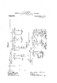
- v 1 n-Fig. ll show, connection with the former having a. secondary, 21, connected to I lampsor other vapor devices 3, 4, ,5 a'ndf6.
- Figs. 1 and 2 may all be operated I eluded in the circuits-l illustrated or subjected Y to otherconditions ofrservicei )
- the lamps un arne in the position which it occupies shown in Fig. 2 are marked 34 and 35, and thesystem of Circuits shown is not un- I like that appearing in Fig. lot the drawings.
- the inductance, 36- which acts 'as a starting coil, may lift the iron contactpiece 40 out of contact with the negative electrode 11 thereby'breaking down the negative electrode resistance and causing a flow of current through the entire lamp, in," a manner now common in the art.
- the inductance, 36- which acts 'as a starting coil
- the starting coil may joggle the container itself in such manner as to interrupt'the contact of. an iron magnetlc'plece or other contact-piece circuit leading from the conductor 7 througha conductor, 42, to the-conductor 38 and through the resistance 39 and the'contact, 40., the electrode 11, the coils 36 and 37 back to the conductor, 22, and; the neutral .point or some intermediate point of the secondary 21.
- an iron magnetlc'plece or other contact-piece circuit leading from the conductor 7 througha conductor, 42, to the-conductor 38 and through the resistance 39 and the'contact, 40., the electrode 11, the coils 36 and 37 back to the conductor, 22, and; the neutral .point or some intermediate point of the secondary 21.
- the coil 36 may not'only act as a starting coil but also as a sustaining coil.
- the startingcircuit may be cut out as soon as the operation of starting shall have takenplace, such a cut-out being illustrated in' connection with the-lamp 34' as will presently be described.
- This 0011 is shown inoperative relation lar" with'a magnetic contact-piece 40 which is, in the non-operating position of the lamp, out of contact with the negative electrode 11;
- the resistance 39 and thecoil43 are included in theconductor 38 which leads to a cut-out, 44, whose terminals are in contact prior to the,;starting of the apparatus,
- inductance 42 and a cut-out 41 having a -movable element 48 and a second movable element 49, which second element-however,
- the said electrode 11 isgljoiried I through an inductance 46 to the condu'ctor n 22 leading to an intermediate point;. inthe*-.
- the starting anode 59 is con-. nected' to the point 54: of the supply'21- and the supplemental electrode 64 is connected through the.resistance-65, the conductor 62 and the cut-out 57, to the point 55 of the The cut out 57 is-controlled by magnetism from the inductance coil 36 connected be- 'tween the lead of the negative electrode 11' and the intermediate point-of the transdiate point ofthe'windiug 21. vThe current 40 former secondary 21.”
- the main operating electrodes 9 and 10 are connected respectively to the. points 55 and; 54 in2l. 'The special ballast or resistance device 61 10- cateddnthe lead of the electrode 10 serves to control the flow of current duririg nor mal operation.
- the supplev mentary anode 64 touches the surface of the cathode-l1.
- the application of voltageto the transformer winding 21 then impresses voltage between-theelectrodes 9 and 10 and passes current through the point'55 the cut out 57 which remains closed until opened-by the coil 36, the conductor. 62, the resistance 65, the supplementary electrode 64; the
- the ballast device 60 which is similar to the device 61 and helps to control the flow of current to an intermethus passed through the coil 36 lifts the electrode- 64a breaking down, the negative electrode resistance-of the cathode. 11' and allows the favorably located electrode59 to draw current through the light giving-tube where it normally will run upon the electrodes 9; and 10."
- Fig. 4 illustrates still another starting cir-' cuit in which the normal electromotive force is supplied from between the points 54 and.
- the terminal 56 is connected through a cut-out, 57, through a resistance, 58, to a supplemental or auxiliary positive electrode, 59.
- the negative electrode 11 isjoined through an-indiictance 36 and a ballast, 60, to an intermediate point in the v transformer secondary, while: the terminal 54 is connected through a ballast, 61, to the electrode 10.
- the electrode 9 is connected ts a point'55 in the's'e'condary 2 1. From the-circuit, 62, connecting, the.
- a branch, 63 is led oif to a container, said contact, 64, being normally duringthe non-operating condition 'of the lamp.
- a resistance,f65 will usually be in cluded in the branch 63.
- the lamp operates in a manner alreadyset forth in detail in connection with other forms of circuits- H i I'n-Fig. 5 a-modified form of starting-circuitis shown whereina supplemental elecon unbalanced. elect-romotive force.
- tact 64 the electrode 11, inductance 36, balshown an extra potential-is conveyed byx-this. circuit and the inductance-36 is energized. sufiiciently to operate both .the contact 64- and also the cut-out 57 whereby the flow of s5 under the influence of the extra potential, which flows .to the electrode 59.
- bal 1 In a'system of electrical distribution-g a ⁇ n'umber of vapor devices, each having a common negativeelectrode and a plurality lead connected with a contact, 64 inside the p in connection with the negative electrode 11 trode, 59, is used for starting up the lamp .
- the Y sustaining coil '36 acts directly upon the 5, 1906, in which parent application laims are made upon the apparatus described 1'00 contact and the negative electrode 11 until the lamp startsinto operation.
- a cut-out' may be employed in connection with this 'circuit as already described. in connection 6 tion with all these lamps or vapor devices ballasts may be used or dispensed witl1:ac.. cording to-the needs or requirements.
- This circuit through each of' 'thesaid devices, a. circuit in shunt tothe said metallic circuit 'aroundeach of the said devices, and
- Starting means for mercury vapor apparatus including a hermetically sealed and completely exhausted container inclosinga plurality of anodes and a vaporizable reconstructing cathode, comprisinga s'upplefmentary anode normally out of contact with: trode so as to break.-;
- connectionrtrom the supplementary anode to a main anode, another connection outside of the" device, and means located in ,the last-named connection for causing anontact between the negative electrode and the supplementary'anode.
- formercury vapor apparatus including; a hermetically 7 sealed and completely exhausted container inclosing' a plurality of anodes and a yaporizable reconstructingcathode, comprising a supplementary anode normally out of contact with the cathode, butadapted to contact therewith, a cohn'ection from the supplementary anode to a main anode, another connection from the supplementary anode to the cathode outside of the device,- andmeans located in the last namedconnection for causing acontact .between the negative electrode and the sup ple'mentary anode,' together with a cutout and 'magnet coil for interrupting the last named circuit, said cut-out being responsive to the magnetic coil located in the lead of the cathode.
Landscapes
- Engineering & Computer Science (AREA)
- Power Engineering (AREA)
- Mechanical Engineering (AREA)
- Physical Or Chemical Processes And Apparatus (AREA)
Description
, P. H. THOMAS. SYSTEM 01? LIGHTING AND DISTRIBUTION BY VAPOR LAMPS.'
APPLICATION PILED AUG. 20, 1907; I I h Patnted-Aug. 30, 1910.
2 SHEETS-SHEET 1.
' v P. H. THOMAS. SYSTEM OF LIGHTING AND DISTRIBUTION BY VAPOR LAMPS."
V APPLICATION FILED AUG. 20, 1907. S 968,897.
W o: I Y Swen-ho? Patented Aug. 30, 1910[ ZSHEETSSHEIIT 2.
' UN TED:
, rEnoY n. 'trnoir'as, or} mamas; ana'snv; kssrononrog coorna Hnwrrr nnnormo'oomranza oonrbrcarr-rorr-OS-NnW YORK.
SYSTEM or i ren'r nvs' Ann sr'siesms Y varon nii virs.
. amma]. ters n w; 1 Patented Au 30,1910.
Original application and May 5, i906, 'seriarnoi 515,276. Divided.aiid'this application filed August 20,
To-cdlwhom mam;- Y
-'-Be it knownwthat I, PERGY HOLBhOOK- @Tnoims, a'citizenof the United States,iand
resident of'Mon tclair, county of Essex, State }ot l\ e;W-' Jersey,- have invented certain new and useful Improvements 1Ilf S.ySteII1S of Lighting and Distribntion by Vapor-Lamps,
"or'gwhichthe following is, a specification.
7 Systems "or electrical distributionfvvhereby already been disclosed,- in which systems the W lamps or'otherdevice's arejsituatel in more or-less close proximity .to each other, so that:
the" energy losses in: distribution are com- -ati l-- ll. Ithens-howevr that. V P m Vey sma e f 'ma1ns..1, andi2, a primary, 20, of a transin other cases requiring the distribution .0
current by vapor electric; devices, these devices maybe widely 'se fainted, in such 11 manner-that there woul normallybe very considerable; energy losses uni-transmission,
or inconveniences-v of control might be dei-' e loped,-ri f the-transmission should be installedjaecordiri to the usual methods of lighting streets br buildings. To'avoidthese difiicu-ltieslihavejinvented a novel system. oi
I cireu'its adapted: to-be utilized with alternat- --in g orflOther'kindS-bf current,,as may be 30 found .suitableg'jandthe system. is applicable to vapor; 1am s andtouother forms of vapor apparatus.
n; this system of circuits *economy. o'fdistribution is .obtained by the utilizatidn of a comparativelyhigh transmission voltage,.aud by-dividing this voltage among anumb er of lamps or other ,vapor devices. I; 111Ly,}()1 m'd y not, supply several such C11- cuits from a common source.
The present inventlon ontemplates the providing of starting means for the vapor apparatus and means for. providing-that disturbances-in'one of the said vapor devices -shall not Seriously influence the other.de-.
vices; In connection with the starting apparatus, it-isnow Well-knownthat automatic evicesfor this purpose may either actuate the container itself soas to cause alocal rupture of the c ircu it or may operate magnetically an iron element ofthe apparatus for the same'punpose; This is said Without regard to any otherm'ea-ns for starting, it being only understood that x'the't-ypes of .j startingapparatus are now s'uificiently well lrnown so thatillustrationof one such type is sufficient to constitute-'it'an equivalent of other" types now common: in the art." 1
v Inthe circuitsillustr-ted, it's not intended -that each individual lamp shallbe oper which it is, shown; but .it ,may' be; combined ated only upon-the circuit in connection w th n v I c v I '60 w1th= {other clr'cult-s shown or described, as
showing starting. means adapted to be used Q in. connectionjw-iththese circuits.- Figs. 3, Aand 5 1llustrate-other starting circuits'and devices.
v 1 n-Fig. ll show, connection with the former having a. secondary, 21, connected to I lampsor other vapor devices 3, 4, ,5 a'ndf6.
*IITthe case or the lamps 3 and 4 Ishowatap, 22', leading from an intermediatepoint of the-secondary 21 and "connected through a ballast, 23,.tin the case of the lamp 3 and .without s iieli ballast' inthe case of the lamp 4115c the negative electrodes 11 of these lamps. "Inthe circuit of the negative electrode in each instance is a choke coil or inductance 16, The. lamps .3 andfl are operated on a three-Wire system of circuits, and the operation thereof is sufliciently clear, Without fur- "therdetailed comment; On the other hand, the lamps 5 and. 6 may be ,operatedfrom the same transformer by utilizing the full poten tial between the terminals of the secondary 21 without relyingupon the tap or middle Wire 22. i
, It will be understood that the systems repfrom the constant potential mains l and 2 or that any group of them may be so operated,
resented-by Figs. 1 and 2 may all be operated I eluded in the circuits-l illustrated or subjected Y to otherconditions ofrservicei )The lamps un arne in the position which it occupies shown in Fig. 2 are marked 34 and 35, and thesystem of Circuits shown is not un- I like that appearing in Fig. lot the drawings.
In connection with the'lamp 33, whichis before starting, I connect with the negative :.-electrode 11 of the lam a pair of coils, 36
and 37, which are inclu ed between the said negative electrode. and the-neutral wire, 22
v leadingtoaniintermediate point of the coil I21; These two coils 36 and 37 may be combinedin one structure, ifdesired. In shunt to the lead of the electrode I provide a V conductor, 38, including a resistance, .39,
leading to aisupplemental positive electrode,
40, which may be of some sol-id magnetic material, as iron, dipping into the negative electrode, 11. When energyis applied to the system the inductance, 36-, which acts 'as a starting coil, may lift the iron contactpiece 40 out of contact with the negative electrode 11 thereby'breaking down the negative electrode resistance and causing a flow of current through the entire lamp, in," a manner now common in the art. Of'course,
instead of moving. a magnetic contact-piece away from the negative electrode, the starting coil may joggle the container itself in such manner as to interrupt'the contact of. an iron magnetlc'plece or other contact-piece circuit leading from the conductor 7 througha conductor, 42, to the-conductor 38 and through the resistance 39 and the'contact, 40., the electrode 11, the coils 36 and 37 back to the conductor, 22, and; the neutral .point or some intermediate point of the secondary 21. Thus there is atfirst a complete metallic circuit carrying suflicient-potential for energizing the starting coil-36 and afterward the current passes through the vapor of the lamp 33 'and maintains the vapor device in operation. The coil 36 may not'only act as a starting coil but also as a sustaining coil.
The startingcircuit may be cut out as soon as the operation of starting shall have takenplace, such a cut-out being illustrated in' connection with the-lamp 34' as will presently be described.
In connection with the lamp 34 show a resistance, 39, in shunt between the. positi e electrode 10 and the negativeelectro'de, 1-1, while inthe same shuntis shown a coil. 43,
acting as a starting coil for the apparatus. This 0011 is shown inoperative relation lar" with'a magnetic contact-piece 40 which is, in the non-operating position of the lamp, out of contact with the negative electrode 11; The resistance 39 and thecoil43 are included in theconductor 38 which leads to a cut-out, 44, whose terminals are in contact prior to the,;starting of the apparatus, One
of the terminals, say 45, of the said cut-out is movable and is capable of being acted upon by an inductance, 46, in series with the :vapor'idevice 34. The actiongof starting is accomplished by transmitting energy through a circuit'represented by the branch' 7, the lead 42 extending to the'positive else-- trode 10,. the: branch 38 including the resistance 39, the coil 43, the inductance 46 and'the wire 22 leading to an interm-ediate point in the secondary 21'. 'This constitutes 1 a metallic path-, which serves to'complete circuit of considerable potential between the .branch 7 and the wire 22. When ,this circuit v is traversed by current the coil 43 being en-ii ergized brings the contact piece 40 into 0011- whereupon current. passing through the inductance, 46, operates the movable element .nection with the negative electrode 11 45 of the cut out 44 and opens-the described shunt circuit. Thereu pon the'contact piece 40 is released from connection with the el'ecf trode 11 and the negative electroderesistanceat the said electrode is broken down and current passes through the lamp 3 4.
In connection with thelamp 35 in Fig. 2'1
' show a starting-circuit in-which a path: for
the current 'is first completed through the branch 7, the shunt 38, the resistance '39, anv
normally standsin' a fixed positioneqQIVr' alent to that shown. a The circuit beyond th coil 42 passes to the 'elem'ent49-and irom'thp element 48 it passes tov the le'ad 50 'runnin g; to a supplemental electrode 51 to which is'z I connected a contact piece, 52, eXteIidrng'i'nto proximity to or contact with thenegativef."
secondary 21. When energy is applied to thedescribed circuit the starting coils-42 draws toward the right as shown in Fig 2 the. container 35, ithis' being accomplished by means; of a magnetic-ring, band, or e015 said 53, surrounding the/lower end of the container to which collar the element 48 may be. joined. "This separates the con tacts ,48 and "49- and interrupts'the circuit of again closed betwecn 48 and 49 by'the' if'e-' lease of. the container In this way' an-ag'i- Y tation of' the conta-iner is. brought about the magnet 43 after which the :circuit iswhich alternately makes and breaks: the cir cuit inside the vacuum chamber between'the .contact- 52. and the. negative electrode which process continues until current flows? .between;th main electrodes 9' and 10 and. the saidnegative electrode 11 whereupon the inductance 16 acts to withdraw'the-com" tact ele'ment49 out of ran'ge of-th'eielementsupply 21. The cut-out 57 is operated by a sufficient flow of current through the coil 36,
48,- and thereby permanently cut; out the short-circuit originally described.
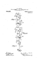
In Fig. 3 the starting anode 59 is con-. nected' to the point 54: of the supply'21- and the supplemental electrode 64 is connected through the.resistance-65, the conductor 62 and the cut-out 57, to the point 55 of the The cut out 57 is-controlled by magnetism from the inductance coil 36 connected be- 'tween the lead of the negative electrode 11' and the intermediate point-of the transdiate point ofthe'windiug 21. vThe current 40 former secondary 21." The main operating electrodes 9 and 10 are connected respectively to the. points 55 and; 54 in2l. 'The special ballast or resistance device 61 10- cateddnthe lead of the electrode 10 serves to control the flow of current duririg nor mal operation.
The operation of thedevice' is as follows:
' In the non-operating condition the supplev mentary anode 64 touches the surface of the cathode-l1. The application of voltageto the transformer winding 21 then impresses voltage between-theelectrodes 9 and 10 and passes current through the point'55 the cut out 57 which remains closed until opened-by the coil 36, the conductor. 62, the resistance 65, the supplementary electrode 64; the
cathode 1-1,,the-i3oil36, the ballast device 60, which is similar to the device 61 and helps to control the flow of current to an intermethus passed through the coil 36 lifts the electrode- 64a breaking down, the negative electrode resistance-of the cathode. 11' and allows the favorably located electrode59 to draw current through the light giving-tube where it normally will run upon the electrodes 9; and 10." The resistances 65 and 58' serve to control the current in the electrodes 64 and 5,9. .The=coil 36 ultimately opens the cutout 57' and thusdiscontinues current in starting circuit. I
. Fig. 4 illustrates still another starting cir-' cuit in which the normal electromotive force is supplied from between the points 54 and.
55 of a transformer secondary or other suitable source while an extra potential is supplied by a coilextending fromthe. point 55 to a point56. The terminal 56 is connected through a cut-out, 57, through a resistance, 58, to a supplemental or auxiliary positive electrode, 59. The negative electrode 11 isjoined through an-indiictance 36 and a ballast, 60, to an intermediate point in the v transformer secondary, while: the terminal 54 is connected through a ballast, 61, to the electrode 10. The electrode 9 is connected ts a point'55 in the's'e'condary 2 1. From the-circuit, 62, connecting, the. point 56 with the electrode-59, a branch, 63, is led oif to a container, said contact, 64, being normally duringthe non-operating condition 'of the lamp. A resistance,f65, will usually be in cluded in the branch 63. When the-current j is turnedoli, a complete metallic circuit is and 63 through the resistance '65, the conlast 60,"to an intermediate point inetheseconclary 21. By virtue of the arrangement current through the'apparatus is initiated the vapor apparatus-prior to the operation of the cut-out: 57 long enough 'toaccomplishthe starting of the-apparatus. Afterward,
the lamp operates in a manner alreadyset forth in detail in connection with other forms of circuits- H i I'n-Fig. 5 a-modified form of starting-circuitis shown whereina supplemental elecon unbalanced. elect-romotive force.
magnetic starting contact '64 causing" repeated makes and breaks between the said with othersy st'em's of starting. In-connec= is .t'rue'of the ballasts shown at' 66- and 61 in Figs; 3, 4 and 5 which either may, or may accelerated current may be provided by conp oint, a's indicated in the said figure, where- .by an unbalancing of the circuit is produced last 61 and also for the purpose of securing the application of an accelerated electromotive force as already set forth. v
This application is a'division of my application Serial Number 315,276, filed May herein. 1 I cla m as my invention of positiveelectrodes, a temporary metallic made from the point 56 over the circuits.62-
. means included in the shunt circuit for indevice;
having acommon negative electrode andfa contact- 'With i the ne ative electrode and. thereby initiate a loc 3.111 a system of electrical distribution, a number of vapor electric devices, each. having a common negative electrode and a 'plurality of positive electrodes, a" supplemental positive electrode adapted to 'make' "electrode around the said supplemental posi- L tive electrode means for operating the said plurality of positive electrodes," a supple mental-positive electrode. adapted to make contact with the commonnegative electrode,
circuit connections to the said supplemental positive electrode, a Shlllllllt) the negat ve electrode around the said supplemental posi tive electrode, and means -foroperating the said supplemental elec how of current.
contact withthe-common negative electrode, circuit connections to said supplemental positive electrode, a shunt 'to the negative supplemental electrode so as to break con- "ltact with the negative electrode and. thereby initiate a localflow'of current, and means for interrupting the described-.shuntcircuit. ,4. In a systeniof electrical distribution,
an'umloer of vapor electric devices, each a common negative electrode and a for interrupting the metallic circuit ipside supply, a plurality -of mercury vapor de-- point ofthesupply tolthe several negative the device. n i,
'15, The combination withlanalternating rality of anodesand a commonvaporizable plied with starting current fromf the source, of a commonconnection frornoneterminal of the supply-toe part ofthe positive'electrode and from -.another terminal of the electrodes.-
Q6; The combination an alternating l a plu rality of mercury vapor devices each comprising a-hermetically sealed '60 and completely exhausted container, a plurality ofanodes and 'a common vaporizable cathode therein, and 'a' starting electrode supplied with startingj 'current from the --.'source, of a common connection from .one terminal-[of the supply toa portion of the I from the supplementary anodeto the cathode vices eachcomprising a hermetically sealed H for mercury Vapor apparatus incl ding a and completely exhausted container, a plucease? positive electrode and from another terminal of the supply to other. positive electrodes and a commonconn'ection from the intermediate point-ofthe supply to the several negative electrodes, together "with electromagnetic means located between the negative electrode of any device and the line leading to the common intermediate .point of the supply,
'Whereby the initiation of normal: current discontinues its'starting circuit. 1 r
7. Starting means for mercury vapor apparatus including a hermetically sealed and completely exhausted container inclosinga plurality of anodes and a vaporizable reconstructing cathode, comprisinga s'upplefmentary anode normally out of contact with: trode so as to break.-;
the, cathode, butadapted'tocontact there-f with, a connectionrtrom the supplementary anode to a main anode, another connection outside of the" device, and means located in ,the last-named connection for causing anontact between the negative electrode and the supplementary'anode. Y
8."The combination with starting means" formercury vapor apparatus including; a hermetically 7 sealed and completely exhausted container inclosing' a plurality of anodes and a yaporizable reconstructingcathode, comprising a supplementary anode normally out of contact with the cathode, butadapted to contact therewith, a cohn'ection from the supplementary anode to a main anode, another connection from the supplementary anode to the cathode outside of the device,- andmeans located in the last namedconnection for causing acontact .between the negative electrode and the sup ple'mentary anode,' together with a cutout and 'magnet coil for interrupting the last named circuit, said cut-out being responsive to the magnetic coil located in the lead of the cathode.
9.v The combination with starting means roe hermeticallyseale d and completely exhausted container inclosing a plurality of anodes and a vap'orizable reconstructing cathode, comprising a supplementary anode normally out of contact with the'cathode, movable relative to the container and adapted to contact with said cathode, .aconnection from the supplementary anode to a mainanode,
another connection 'from the supplementary completely exhausted container and a plurality of anodes and a vaporiza ble reconstructing cathode therein, and connections from the anodes of the device to the terminals of the supply and a connection from the cathode to an intermediate point'of the supply, of a supplemental electrode Within the device adapted to make and break contact With the cathode together with electromagnetic means for controlling the starting 16 electrode. I M
Signed at New York, in the county of New York, and State of New York; this 17th day of August A. D.- 1907.
PERCY H. THOMAS; Witnesses:
W H. Gerri, THOS. H. BROWN.
Priority Applications (1)
| Application Number | Priority Date | Filing Date | Title |
|---|---|---|---|
| US389364A US968897A (en) | 1906-05-05 | 1907-08-20 | System of lighting and distribution by vapor-lamps. |
Applications Claiming Priority (2)
| Application Number | Priority Date | Filing Date | Title |
|---|---|---|---|
| US1906315276A | 1906-05-05 | 1906-05-05 | |
| US389364A US968897A (en) | 1906-05-05 | 1907-08-20 | System of lighting and distribution by vapor-lamps. |
Publications (1)
| Publication Number | Publication Date |
|---|---|
| US968897A true US968897A (en) | 1910-08-30 |
Family
ID=3037287
Family Applications (1)
| Application Number | Title | Priority Date | Filing Date |
|---|---|---|---|
| US389364A Expired - Lifetime US968897A (en) | 1906-05-05 | 1907-08-20 | System of lighting and distribution by vapor-lamps. |
Country Status (1)
| Country | Link |
|---|---|
| US (1) | US968897A (en) |
-
1907
- 1907-08-20 US US389364A patent/US968897A/en not_active Expired - Lifetime
Similar Documents
| Publication | Publication Date | Title |
|---|---|---|
| US1024495A (en) | Electric-lighting system. | |
| US968897A (en) | System of lighting and distribution by vapor-lamps. | |
| US2096427A (en) | Regulating system | |
| US3325682A (en) | Variable power supply | |
| US1736993A (en) | Light-relay system | |
| EP0080751A2 (en) | Electric arrangement for step-wise controlling the luminance of a gas and/or vapour discharge lamp | |
| US2465103A (en) | Lighting system and apparatus | |
| US2001838A (en) | Power control circuits | |
| US2201898A (en) | Automatic switch | |
| US3863104A (en) | Arrangement for the controllable supply of at least two groups of electric lamps | |
| US1634420A (en) | Electrical translating device | |
| US3679935A (en) | Arrangement for dimming at least two parallel-arranged discharge lamps | |
| US1350170A (en) | Arc-lamp system | |
| US2659035A (en) | Apparatus for operating gaseous discharge tube devices | |
| US682693A (en) | Starting apparatus and circuit for electric lamps. | |
| US946053A (en) | Means for starting serially-operated vapor-converters. | |
| US1079342A (en) | Electric gas or vapor lamp. | |
| US3035207A (en) | Circuit arrangement for operating electric discharge lamp | |
| US2333520A (en) | Electrical protective relay system | |
| US2162533A (en) | Translating device | |
| US1445206A (en) | Thermionic rectifier and circuits therefor | |
| US3371246A (en) | Fluorescent lamp circuit with a voltage boosting transformer convertible to a variable inductance for current regulation | |
| US1110644A (en) | Rectifier for lamps. | |
| US1032928A (en) | Vacuum-tube electric-lighting apparatus. | |
| US454782A (en) | Lamp cut-out and system |