US968799A - Sprue. - Google Patents
Sprue. Download PDFInfo
- Publication number
- US968799A US968799A US54008210A US1910540082A US968799A US 968799 A US968799 A US 968799A US 54008210 A US54008210 A US 54008210A US 1910540082 A US1910540082 A US 1910540082A US 968799 A US968799 A US 968799A
- Authority
- US
- United States
- Prior art keywords
- sprue
- gate
- head
- holder
- relation
- Prior art date
- Legal status (The legal status is an assumption and is not a legal conclusion. Google has not performed a legal analysis and makes no representation as to the accuracy of the status listed.)
- Expired - Lifetime
Links
- 208000015943 Coeliac disease Diseases 0.000 description 74
- 238000000465 moulding Methods 0.000 description 8
- 239000004576 sand Substances 0.000 description 2
- 238000010276 construction Methods 0.000 description 1
Images

Classifications
-
- B—PERFORMING OPERATIONS; TRANSPORTING
- B22—CASTING; POWDER METALLURGY
- B22C—FOUNDRY MOULDING
- B22C7/00—Patterns; Manufacture thereof so far as not provided for in other classes
- B22C7/02—Lost patterns
Definitions
- This invention relates to sprues for molders use, and has for its object the provision of a device of this character particularly adapted for use in connection with molding machines, the sprue being constructed in such manner that it will automatically en ⁇ gage the gate and withdraw it from the sand as the rammer head of the molding machiicile is elevated after having rammed the san Further objects and advantages of the invention will be se't forth in the detailed description which now follows.
- Figure 1 is a side elevation of a sprueshowing the same in engagement with a single flat gate
- Fig. 2 is a view of a sprue showing the same in engagement with a double gate
- Fig. 3 is a vertical section of a sprue showing the same in engagement with a round gate
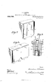
- Fig. 4 is a View of a sprue similar to that shown in Fig. 1, but illustrating an adjustable and yielding connection between said sprue and the rammer head of the press to which said sprue is secured
- Fig. 5 is a vertical section upon line 5 5 of Fig. 1
- Fig. 6 is a horizontal section upon line 6-6 of Fig. 4, Fig.
- Fig. 7 is a perspec'tive view of the sprue shown in Fig. 1
- Fig. 8 is a perspective view of the sprue shown in Fig. 2
- Fig. 9 is an enlarged sectional view illustrating the catch shown in Fig. 3.
- the numeral 5 designates the sprue proper.
- This sprue is provided with overhanging flanges 6, to form ways 7 for the reception of 'the gate 8.
- This gate is provided with an opening 9 for the reception of a spring pressed latch 10.
- This spring pressed latch is carried by the sprue 5 and serves to lock the sprue to the gate 8 when said sprue descends to its lowermost position.
- the structure is substantially the same except that the sprue 5 is adapted to engage two gates 8 provided with latches 10 that are in all respects similar t0 the latch 10 shown in Fig. 5.
- a round sprue 52 is shown in engagement with a round gate 82.
- This round gate carries a knob 12 at its upper end which serves a purpose hereinafter set forth.
- the gates 8 8 and 82 are all provided with dowel pins 11, at their lower ends adapted to enter recesses formed in a trimmer 14. This trimmer is set directly on a pattern in fiat gating and on the pattern gates in round gating and is positively secured thereto in any desired manner.
- the detachable latch between the sprue and the gate comprises a pair of levers 15 which are piv.- otally mounted as at 16.
- a spring 17 bears between the upper portions of these levers and the heads 18 thereof are forced by said spring int-o engagement with the knob 12.
- a pin 19 prevents these levers from ever closing any more than is shown in Fig. 9. It will be seen that the upper ends of t-hese levers extend through the rammer head 20 of a molding machine, and that the sprue is positively connected to said head by screws 21. It is of course apparent that other means may be provided for securing the sprue to the rammer head.
- the numeral 20 designates a rammer head of an ordinary molding machine.
- the sprue illustrated in this form of the device is substantially like that illustrated in Fig. 1 and the same reference numerals have been employed upon corresponding parts.
- the structure shown in this iigure,however, provides a yielding and adjustable connection between the sprue and the head 20.
- This form of the device comprises a sprue holder 22 which is box like in form and which has slots 23 formed in its ends for the reception of pins 24 carried by the sprue 5.
- Springs 25 bear between the top of the sprue and the sprue holder.
- this structure provides a vertically yielding connection between the sprue and the sprue holder.
- a bolt 26 passes through the head 20 and is provided with a tightening nut 27.
- This bolt is provided with a disk 28 upon its lower end and said bolt passes through a plate 29 which is carried by the sprue holder 22. It will be noted that the opening in plate 29 through which the bolt passes is of considerable greater diameter than the bolt so that horizontal movement in every direction with relation to the head 20 is permitted the sprue holder and consequently the sprue, when the nut 27 is loosened, see Fig. 6.
- the operation of the device is as follows: In the form of the device illustrated in Figs. l, 2, 3, 5, 7, S, and 9, the sprue is secured directly to the head 20 and when said head descends to pack the sand in the mold", the sprues slip down over the gates until the catches l0 or l2 as the case may be, ⁇ engage the gates. Vhen the head rises it is apparent that the gates will be withdrawn with them.
- the operation is substantially the same in the form of the device shown in Fig. t, the only dierence being the yieldable and adjustable connection between the sprue and the rainmer head.
- the combination with a sprue, of a gate means for supporting said gate in a vertical position with relation to a pattern, said sprue being adapted to slide down over said gate, and means for locking said gate to said sprue at a predetermined point in the downward movement of said sprue.
- the combination with a sprue, of a gate means for supporting said gate in a vertical position with relation to a pattern, said sprue being adapted to slide down over said gate, and means for locking said gate to said sprue at a predetermined point in the downward movement of said sprue, said means comprising a spring latch.
- the combination with a sprue, of a gate means for supporting said gate in a vertical position with relation to a pattern, said sprue being adapted to slide down over said gate, and means for locking said gate to said sprue at a predetermined point in the downward movement of said sprue, said sprue being connected to the raminer head of a molding machine.
- the combination with a sprue, of a gate means for supporting said gate in a vertical position with relation to a pattern, said sprue being adapted to slide down over said gate, means for locking said gate to said sprue at a predetermined point in the downward movement of. said sprue, and means for connecting said sprue for adjustable movement in every direction in a horizontal plane with relation to the head of a molding machine.
- the combination with a sprue, of a gate means for supporting said gate in a vertical position with relation to a pattern, said sprue being adapted to slide down over said gate, means for locking said gate to said sprue at a predetermined point in the downward movement of said sprue, and means for yieldingly and adjustably connecting said sprue to the head of a molding machine.
Landscapes
- Engineering & Computer Science (AREA)
- Mechanical Engineering (AREA)
- Moulds For Moulding Plastics Or The Like (AREA)
Description
Patented Aug. 30, 1910.
C. I. PRoWsE.
SPRUE.
APPLICATION FILED DBO. 9, 190s. RENEWED JAN. 25, 1910.
1HE :vonnis PETERS co., wAsHmnroN. u, c.
0. J. PROWSE.
SPRUE.
APPLICATION FILED 12H19, 1908. RENEWBD JAN. 25, 1910.
Patented Aug. 30, 1910.
2 SHEETS-SHEET 2.
L x 1 )111W UNITED srATEs PATENT oEEICE.
CORNELIUS J. PEowSE, or CAMBRIDGE, MASSACHUSETTS, ASSINoR 0E CNE-HALE To WALDRoN E. PEowsE, or CHAELoTTETowN, PRINCE EDWARD ISLAND, CANADA.
sPRUE. v
Patented Aug. 30, 1910.
Application filed December 9, 1908, Serial No. 466,724. Renewed January 25, 1910. Serial No. 540,082.
To all 'whom 'it may concern.'
Be it known that I, CORNELIUS J. PRowsE, a citizen of the United States of America, residing at Cambridge, in the county of MiddleseX and State of Massachusetts, have invented certain new and useful Improvements in Sprues, of which the following is a specification.
This invention relates to sprues for molders use, and has for its object the provision of a device of this character particularly adapted for use in connection with molding machines, the sprue being constructed in such manner that it will automatically en` gage the gate and withdraw it from the sand as the rammer head of the molding machiicile is elevated after having rammed the san Further objects and advantages of the invention will be se't forth in the detailed description which now follows.
In the accompanying drawing, Figure 1 is a side elevation of a sprueshowing the same in engagement with a single flat gate, Fig. 2 is a view of a sprue showing the same in engagement with a double gate, Fig. 3 is a vertical section of a sprue showing the same in engagement with a round gate, Fig. 4 is a View of a sprue similar to that shown in Fig. 1, but illustrating an adjustable and yielding connection between said sprue and the rammer head of the press to which said sprue is secured, Fig. 5 is a vertical section upon line 5 5 of Fig. 1, Fig. 6 is a horizontal section upon line 6-6 of Fig. 4, Fig. 7 is a perspec'tive view of the sprue shown in Fig. 1, Fig. 8 is a perspective view of the sprue shown in Fig. 2, and Fig. 9 is an enlarged sectional view illustrating the catch shown in Fig. 3.
Like numerals designate corresponding parts in all of the figures of the drawings.
Referring particularly to Figs 1, 5, and 7, the numeral 5 designates the sprue proper. This sprue is provided with overhanging flanges 6, to form ways 7 for the reception of 'the gate 8. This gate is provided with an opening 9 for the reception of a spring pressed latch 10. This spring pressed latch is carried by the sprue 5 and serves to lock the sprue to the gate 8 when said sprue descends to its lowermost position.
In the form of the device illustrated in Figs. 2 and 8, the structure is substantially the same except that the sprue 5 is adapted to engage two gates 8 provided with latches 10 that are in all respects similar t0 the latch 10 shown in Fig. 5.
In the form of the device shown in Figs. 3 and 9, a round sprue 52 is shown in engagement with a round gate 82. This round gate carries a knob 12 at its upper end which serves a purpose hereinafter set forth. The gates 8 8 and 82 are all provided with dowel pins 11, at their lower ends adapted to enter recesses formed in a trimmer 14. This trimmer is set directly on a pattern in fiat gating and on the pattern gates in round gating and is positively secured thereto in any desired manner.
As is best illustrated in Fig. 9, the detachable latch between the sprue and the gate comprises a pair of levers 15 which are piv.- otally mounted as at 16. A spring 17 bears between the upper portions of these levers and the heads 18 thereof are forced by said spring int-o engagement with the knob 12. A pin 19 prevents these levers from ever closing any more than is shown in Fig. 9. It will be seen that the upper ends of t-hese levers extend through the rammer head 20 of a molding machine, and that the sprue is positively connected to said head by screws 21. It is of course apparent that other means may be provided for securing the sprue to the rammer head.
Referring now particularly to Figs. 4 and 6, the numeral 20 designates a rammer head of an ordinary molding machine. The sprue illustrated in this form of the device is substantially like that illustrated in Fig. 1 and the same reference numerals have been employed upon corresponding parts. The structure shown in this iigure,however, provides a yielding and adjustable connection between the sprue and the head 20. This form of the device comprises a sprue holder 22 which is box like in form and which has slots 23 formed in its ends for the reception of pins 24 carried by the sprue 5. Springs 25 bear between the top of the sprue and the sprue holder. It will therefore be seen that this structure provides a vertically yielding connection between the sprue and the sprue holder. A bolt 26 passes through the head 20 and is provided with a tightening nut 27. This bolt is provided with a disk 28 upon its lower end and said bolt passes through a plate 29 which is carried by the sprue holder 22. It will be noted that the opening in plate 29 through which the bolt passes is of considerable greater diameter than the bolt so that horizontal movement in every direction with relation to the head 20 is permitted the sprue holder and consequently the sprue, when the nut 27 is loosened, see Fig. 6.
The operation of the device is as follows: In the form of the device illustrated in Figs. l, 2, 3, 5, 7, S, and 9, the sprue is secured directly to the head 20 and when said head descends to pack the sand in the mold", the sprues slip down over the gates until the catches l0 or l2 as the case may be,` engage the gates. Vhen the head rises it is apparent that the gates will be withdrawn with them. The operation is substantially the same in the form of the device shown in Fig. t, the only dierence being the yieldable and adjustable connection between the sprue and the rainmer head.
From the foregoing description, it will be seen that simple and eicient means are herein provided for accomplishing the objects of the invention, but while the elements shown and described are well adapted to serve the purposes for which they are intended, it is to be understood that the invent-ion is not limited to the piecise construction set fort-h but includes within its purview such changes as may be made within the scope of the appended claims.
Having described my invention, what I claim is:
l. In a device of the character described, the combination with a sprue, of a gate, means for supporting said gate in a vertical position with relation to a pattern, said sprue being adapted to slide down over said gate, and means for locking said gate to said sprue at a predetermined point in the downward movement of said sprue.
2. In a device of the character described, the combination with a sprue, of a gate, means for supporting said gate in a vertical position with relation to a pattern, said sprue being adapted to slide down over said gate, and means for locking said gate to said sprue at a predetermined point in the downward movement of said sprue, said means comprising a spring latch.
3. In a device of the character described, the combination with a sprue, of a gate, means for supporting said gate in a vertical position with relation to a pattern, said sprue being adapted to slide down over said gate, and means for locking said gate to said sprue at a predetermined point in the downward movement of said sprue, said sprue being connected to the raminer head of a molding machine.
t. In a device of the character described, the combination with a sprue, of a gate, means for supporting said gate in a vertical position with relation to a pattern, said sprue being adapted to slide down over said gate, means for locking said gate to said sprue at a predetermined point in the downward movement of. said sprue, and means for connecting said sprue for adjustable movement in every direction in a horizontal plane with relation to the head of a molding machine.
In a device of the character described, the combination with a sprue, of a gate, means for supporting said gate in a vertical position with relation to a pattern, said sprue being adapted to slide down over said gate, means for locking said gate to said sprue at a predetermined point in the downward movement of said sprue, and means for yieldingly and adjustably connecting said sprue to the head of a molding machine.
6. In a device of the character described, the combination with a sprue, a gate over which said sprue is adapted to slide, means for holding said gate in a vertical position with relation to a pattern, Va sprue holder, a.
sliding connection between said sprue and said sprue holder, and a spring between said sprue and said sprue holder. 7. In a device of the character described, the combination with a sprue,- a gate over which said sprue is adapted to slide, means'L for holding said gate in a vertical position with relation to a pattern, a sprue holder, a sliding connection between said sprue and said sprue holder, a spring between said sprue and said sprue holder, and an adjust-. able connection between said sprue holder and the head of a molding machine.
In testimony whereof I aflix my signature in presence of two witnesses.
CORNELIUS J. PROWSE. V'itnesses J. WV. BRITTON, E. F. OBER.
Priority Applications (1)
| Application Number | Priority Date | Filing Date | Title |
|---|---|---|---|
| US54008210A US968799A (en) | 1910-01-25 | 1910-01-25 | Sprue. |
Applications Claiming Priority (1)
| Application Number | Priority Date | Filing Date | Title |
|---|---|---|---|
| US54008210A US968799A (en) | 1910-01-25 | 1910-01-25 | Sprue. |
Publications (1)
| Publication Number | Publication Date |
|---|---|
| US968799A true US968799A (en) | 1910-08-30 |
Family
ID=3037189
Family Applications (1)
| Application Number | Title | Priority Date | Filing Date |
|---|---|---|---|
| US54008210A Expired - Lifetime US968799A (en) | 1910-01-25 | 1910-01-25 | Sprue. |
Country Status (1)
| Country | Link |
|---|---|
| US (1) | US968799A (en) |
Cited By (1)
| Publication number | Priority date | Publication date | Assignee | Title |
|---|---|---|---|---|
| US3036349A (en) * | 1960-03-30 | 1962-05-29 | Edgerton Rollie | Sprue for molding apparatus |
-
1910
- 1910-01-25 US US54008210A patent/US968799A/en not_active Expired - Lifetime
Cited By (1)
| Publication number | Priority date | Publication date | Assignee | Title |
|---|---|---|---|---|
| US3036349A (en) * | 1960-03-30 | 1962-05-29 | Edgerton Rollie | Sprue for molding apparatus |
Similar Documents
| Publication | Publication Date | Title |
|---|---|---|
| US1601051A (en) | Window lock | |
| US968799A (en) | Sprue. | |
| US887814A (en) | Mold for hollow concrete blocks. | |
| US2563317A (en) | Locking device for luggage compartment lids | |
| US2240268A (en) | Dowel | |
| US1450443A (en) | Gate latch | |
| US1493118A (en) | Lock for foundry flasks | |
| US1619784A (en) | Door for cottonseed boxes | |
| US632A (en) | David beuce | |
| US101033A (en) | Improvement in machines for forming molds | |
| US1902523A (en) | Machine fob making cement blocks | |
| US1316259A (en) | Plangqrxph co | |
| US465090A (en) | Henry f | |
| US630884A (en) | Mold for casting waste-traps. | |
| US1069383A (en) | Molding-machine. | |
| US764076A (en) | Gate-latch. | |
| US439430A (en) | Sand-molding machine | |
| USRE15307E (en) | thomas | |
| US332834A (en) | Sand-molding machine | |
| US586336A (en) | Molding device | |
| US890919A (en) | Mold-making machine. | |
| US1600085A (en) | Planting machine | |
| US735347A (en) | Molding-machine. | |
| US904958A (en) | Process of molding sash-weights. | |
| US380300A (en) | William sykes and squire sykes |