US9686808B2 - Centrally managed WI-FI - Google Patents
Centrally managed WI-FI Download PDFInfo
- Publication number
- US9686808B2 US9686808B2 US14/460,657 US201414460657A US9686808B2 US 9686808 B2 US9686808 B2 US 9686808B2 US 201414460657 A US201414460657 A US 201414460657A US 9686808 B2 US9686808 B2 US 9686808B2
- Authority
- US
- United States
- Prior art keywords
- radio node
- layer
- traffic
- connection
- access gateway
- Prior art date
- Legal status (The legal status is an assumption and is not a legal conclusion. Google has not performed a legal analysis and makes no representation as to the accuracy of the status listed.)
- Active
Links
- 238000000034 method Methods 0.000 claims abstract description 37
- 230000015654 memory Effects 0.000 claims description 17
- 208000036829 Device dislocation Diseases 0.000 claims description 6
- 239000010410 layer Substances 0.000 description 105
- CXUFDWZBHKUGKK-CABZTGNLSA-N Trp-Ala-Gly Chemical compound C1=CC=C2C(C[C@H](N)C(=O)N[C@@H](C)C(=O)NCC(O)=O)=CNC2=C1 CXUFDWZBHKUGKK-CABZTGNLSA-N 0.000 description 47
- 230000006870 function Effects 0.000 description 12
- 230000006855 networking Effects 0.000 description 12
- 238000005516 engineering process Methods 0.000 description 10
- 238000004891 communication Methods 0.000 description 9
- 230000005540 biological transmission Effects 0.000 description 6
- 238000005538 encapsulation Methods 0.000 description 5
- 238000007639 printing Methods 0.000 description 5
- 238000000060 site-specific infrared dichroism spectroscopy Methods 0.000 description 5
- 238000013459 approach Methods 0.000 description 4
- 238000001914 filtration Methods 0.000 description 4
- 230000002776 aggregation Effects 0.000 description 3
- 238000004220 aggregation Methods 0.000 description 3
- 230000027455 binding Effects 0.000 description 3
- 238000009739 binding Methods 0.000 description 3
- 230000001413 cellular effect Effects 0.000 description 3
- 230000003287 optical effect Effects 0.000 description 3
- 238000012545 processing Methods 0.000 description 3
- 238000001228 spectrum Methods 0.000 description 3
- 239000008186 active pharmaceutical agent Substances 0.000 description 2
- 238000010276 construction Methods 0.000 description 2
- 238000010586 diagram Methods 0.000 description 2
- 230000010354 integration Effects 0.000 description 2
- 238000002955 isolation Methods 0.000 description 2
- HRULVFRXEOZUMJ-UHFFFAOYSA-K potassium;disodium;2-(4-chloro-2-methylphenoxy)propanoate;methyl-dioxido-oxo-$l^{5}-arsane Chemical compound [Na+].[Na+].[K+].C[As]([O-])([O-])=O.[O-]C(=O)C(C)OC1=CC=C(Cl)C=C1C HRULVFRXEOZUMJ-UHFFFAOYSA-K 0.000 description 2
- 230000000135 prohibitive effect Effects 0.000 description 2
- 230000035755 proliferation Effects 0.000 description 2
- 230000011664 signaling Effects 0.000 description 2
- RYGMFSIKBFXOCR-UHFFFAOYSA-N Copper Chemical compound [Cu] RYGMFSIKBFXOCR-UHFFFAOYSA-N 0.000 description 1
- 241001025261 Neoraja caerulea Species 0.000 description 1
- 230000003466 anti-cipated effect Effects 0.000 description 1
- 230000006399 behavior Effects 0.000 description 1
- VYLDEYYOISNGST-UHFFFAOYSA-N bissulfosuccinimidyl suberate Chemical compound O=C1C(S(=O)(=O)O)CC(=O)N1OC(=O)CCCCCCC(=O)ON1C(=O)C(S(O)(=O)=O)CC1=O VYLDEYYOISNGST-UHFFFAOYSA-N 0.000 description 1
- 239000003795 chemical substances by application Substances 0.000 description 1
- 229910052802 copper Inorganic materials 0.000 description 1
- 239000010949 copper Substances 0.000 description 1
- 230000001419 dependent effect Effects 0.000 description 1
- 238000013461 design Methods 0.000 description 1
- 230000009977 dual effect Effects 0.000 description 1
- 230000036541 health Effects 0.000 description 1
- 238000013507 mapping Methods 0.000 description 1
- 230000000116 mitigating effect Effects 0.000 description 1
- 238000012544 monitoring process Methods 0.000 description 1
- 238000011330 nucleic acid test Methods 0.000 description 1
- 230000002688 persistence Effects 0.000 description 1
- 230000008569 process Effects 0.000 description 1
- 230000004044 response Effects 0.000 description 1
- 238000012552 review Methods 0.000 description 1
- 239000000523 sample Substances 0.000 description 1
- 238000007493 shaping process Methods 0.000 description 1
- 239000002356 single layer Substances 0.000 description 1
- 238000012360 testing method Methods 0.000 description 1
- 238000012546 transfer Methods 0.000 description 1
- 230000001052 transient effect Effects 0.000 description 1
- 238000013519 translation Methods 0.000 description 1
- 230000005641 tunneling Effects 0.000 description 1
- 239000013598 vector Substances 0.000 description 1
Images


Classifications
-
- H—ELECTRICITY
- H04—ELECTRIC COMMUNICATION TECHNIQUE
- H04W—WIRELESS COMMUNICATION NETWORKS
- H04W76/00—Connection management
- H04W76/10—Connection setup
-
- H04W76/02—
-
- H—ELECTRICITY
- H04—ELECTRIC COMMUNICATION TECHNIQUE
- H04W—WIRELESS COMMUNICATION NETWORKS
- H04W48/00—Access restriction; Network selection; Access point selection
- H04W48/20—Selecting an access point
-
- H—ELECTRICITY
- H04—ELECTRIC COMMUNICATION TECHNIQUE
- H04W—WIRELESS COMMUNICATION NETWORKS
- H04W84/00—Network topologies
- H04W84/02—Hierarchically pre-organised networks, e.g. paging networks, cellular networks, WLAN [Wireless Local Area Network] or WLL [Wireless Local Loop]
- H04W84/10—Small scale networks; Flat hierarchical networks
- H04W84/12—WLAN [Wireless Local Area Networks]
-
- H—ELECTRICITY
- H04—ELECTRIC COMMUNICATION TECHNIQUE
- H04W—WIRELESS COMMUNICATION NETWORKS
- H04W88/00—Devices specially adapted for wireless communication networks, e.g. terminals, base stations or access point devices
- H04W88/16—Gateway arrangements
Definitions
- the subject matter disclosed in this application generally relates to centrally managed Wi-Fi, more specifically, to creating easily scalable centrally-managed Wi-Fi using software defined networking techniques.
- Wi-Fi Alliance there were approximately 1.1 Billion Wi-Fi enabled devices shipped in 2012 alone. With the proliferation of Wi-Fi enabled smartphones, tablets, gaming consoles and embedded household appliances like TVs, an average household has more than five Wi-Fi enabled devices at any given time. Wi-Fi devices support a number vertical applications like health, fitness, smart energy and internet of things (IoT). These and other applications are anticipated to drive the total amount of Wi-Fi shipments per year to double to 2.2 Billion in 2016.
- Wi-Fi technologies such as 802.11a/b/g/n and soon 802.11 u and 802.11 ac has made Wi-Fi the broadband wireless access of choice.
- cloud computing and associated cloud technologies are creating an information technology (IT) revolution of their own.
- IT information technology
- Fat pipes long haul transmission capacity
- Wi-Fi and cloud technologies are expected to usher in a new era of ubiquitous networking and service availability.
- the first generation Wi-Fi access points were standalone APs such as those provided by Linksys, Netgear, etc. Such APs are often referred to as autonomous, independent, or fat APs. Such access points typically have a complete IP router function that includes a local Dynamic Host Configuration Protocol (DHCP) server, a basic network address translation (NAT) port, support for popular port triggering protocols (e.g., such as Universal Plug and Play (UPnP) protocols, and NAT port mapping protocol (PMP)), and a domain name system (DNS) server.
- DHCP Dynamic Host Configuration Protocol
- NAT basic network address translation
- PGP NAT port mapping protocol
- DNS domain name system
- Some of these Wi-Fi access points include basic access control functions (ACL) like media access control (MAC) filtering and time of the day-based internet access restrictions.
- ACL basic access control functions
- MAC media access control
- first generation standalone APs must typically be configured individually. Therefore, to deploy multiple standalone APs (which is becoming the norm), a network administrator must log into and configure each Wi-Fi AP independently, making configuration changes a tedious and error-prone process.
- standalone APs make it difficult for the user to monitor the wireless network in a centralized manner; obtaining statistics such as aggregated bandwidth statistics, usage data, and/or status information across all of the APs in the network must be done manually.
- GUI graphical user interface
- broadband service providers often cannot provide any value added device management services because the Wi-Fi home access point NATs all the IP traffic and hides all device visibility.
- APs e.g. 10 s to a few 100 access points.
- Standalone APs were fast becoming impossible to manage in any scale, so companies began to move to a hierarchical architecture for centralized monitoring and configuration of APs.
- Some such architectures included a Wireless Access Controller designed to scale to a few hundred APs.
- the interface between the AP and controller was proprietary and loosely based on the Control and Provisioning of Wireless Access Points (CAPWAP) protocol (e.g., specified in RFC 5415).
- CAPWAP Wireless Access Points
- the Wi-Fi access and the IP router functions of the standalone AP were split between the dependent AP and the Wireless Access Controller. Since the interface between the controller and AP was vendor specific, the split functionality varied between vendors.
- Other architectures can also include an AP architecture where certain functions of the Wi-Fi MAC were split between the APs and the controller (often referred to as a “split MAC architecture”). This architecture can allow the controller to perform centralized radio frequency (RF) management of APs for interference mitigation and coordination.
- RF radio frequency
- controllers operate at Layer 3 (or higher) and provide centralized management and configuration of the IP control plane, the traffic/forwarding plane, and RF management.
- This configuration e.g., typically implemented on a 1RU or 2RU servers
- This configuration can severely limit the scalability of such a solution to a few hundred APs, which is not suitable for the massive scale of outdoor and residential applications.
- tens of thousands of Wireless Access Controllers would need to be deployed to support millions of concurrently active devices.
- Such a solution would be nearly impossible to manage and would be cost prohibitive since Wireless Access Controllers are very expensive.
- the Wireless Access Controller is a single point of failure, so if a WLAN controller fails then all of the APs connected to that controller will also fail. Dual-redundant controllers, while technically possible, are often cost prohibitive.
- device management and device centric value added services can't be provided because the controller hides the topology and the devices that the controller manages.
- Wi-Fi Wireless Fidelity
- home networks now have more Wi-Fi devices than early enterprise networks.
- Managed Wi-Fi is attractive to residential users because it can offer continuous Wi-Fi access to their smartphones and tablets (post PC devices) across multiple remotely-located radio nodes, as well as device centric value-added services.
- Service provider managed Wi-Fi solutions are also attractive for businesses to allow businesses to lower their IT costs by not needing to procure and deploy their own standalone or controller-based Wi-Fi solutions.
- systems and methods are described herein to provide an architecture that leverages software-defined networking (SDN) principles to provide highly scalable mobile Ethernet over a wide area network (WAN).
- SDN software-defined networking
- WAN wide area network
- the techniques provide for creating a Layer 2 virtual switching domain for the data plane and a separate control plane.
- the Layer 2 domain has the simplicity and agility of Ethernet to provide ultra-scalable Wi-Fi that extends to 10s of millions of devices.
- Disclosed subject matter includes, in one aspect, a computerized method for providing centrally managed Wi-Fi using internet protocol (IP) connections between a central Wi-Fi access gateway and one or more radio nodes, wherein the radio nodes and the Wi-Fi access gateway are connected across a wide area network, and the Wi-Fi access gateway controls Wi-Fi services for Wi-Fi devices connected to the radio nodes.
- IP internet protocol
- a Wi-Fi access gateway establishes an IP connection with a radio node across a wide area network, wherein the radio node is configured to wirelessly connect to one or more Wi-Fi devices located near the radio node.
- the Wi-Fi access gateway receives Layer 2 traffic over the IP connection, wherein the Layer 2 traffic is associated with a Wi-Fi device from the one or more Wi-Fi devices connected to the radio node.
- the Wi-Fi access gateway controls one or more Wi-Fi services for the Wi-Fi device based on the Layer 2 traffic so that the Wi-Fi access gateway can provide centrally managed Wi-Fi for the Wi-Fi device.
- a destination of the Layer 2 traffic is a second Wi-Fi device from the one or more Wi-Fi devices connected to the radio node
- a message is transmitted to the radio node to cause the radio node to locally route traffic between the Wi-Fi device and the second Wi-Fi device so that it is not routed to the Wi-Fi access gateway.
- Transmitting the message to the radio node can include transmitting a message to update a forwarding information base at the radio node to cause the radio node to locally route traffic between the Wi-Fi device and the second Wi-Fi device.
- a destination of the Layer 2 traffic is a second Wi-Fi device connected to a second radio node, wherein the Wi-Fi access gateway is connected to the second radio node by a second IP connection across the wide area network, and the Layer 2 traffic is transmitted to the second radio node over the second IP connection.
- the Wi-Fi device associated with the Layer 2 traffic had a Wi-Fi data connection with a second, different radio node, and that the Wi-Fi device moved so that the Wi-Fi device has a Wi-Fi connection with the radio node instead of with the second radio node, and the Wi-Fi data connection can be maintained with the Wi-Fi device even though it moved from being connected to the second radio node to the first radio node.
- a data connection can be provided between the radio node and the Wi-Fi access gateway using the IP connection, such that the control plane to the radio node is provided using a different connection to the radio node.
- a MAC address associated with the Wi-Fi device is identified in a first Layer 2 data frame received from the Wi-Fi device through the IP connection, and the Wi-Fi device with the radio node.
- Layer 2 data from a second radio node can be received over a second IP connection with the second radio node
- the MAC address associated with the Wi-Fi device can be identified in the Layer 2 data from the second radio node
- the Wi-Fi device can be associated with the second radio node instead of the first radio node to initiate a handover of the Wi-Fi device from the radio node to the second radio node.
- Disclosed subject matter includes, in another aspect, a computing system configured to provide centrally managed Wi-Fi using internet protocol (IP) connections with one or more radio nodes, wherein the radio nodes are connected to the computing system across a wide area network, and the computing system controls Wi-Fi services for Wi-Fi devices connected to the radio nodes.
- IP internet protocol
- the computing system can include a processor configured to run a module stored in memory that is configured to cause the processor to establish an IP connection with a radio node across a wide area network, wherein the radio node is configured to wirelessly connect to one or more Wi-Fi devices located near the radio node, receive Layer 2 traffic over the IP connection, wherein the Layer 2 traffic is associated with a Wi-Fi device from the one or more Wi-Fi devices connected to the radio node, and control one or more Wi-Fi services for the Wi-Fi device based on the Layer 2 traffic so that the Wi-Fi access gateway can provide centrally managed Wi-Fi for the Wi-Fi device.
- a processor configured to run a module stored in memory that is configured to cause the processor to establish an IP connection with a radio node across a wide area network, wherein the radio node is configured to wirelessly connect to one or more Wi-Fi devices located near the radio node, receive Layer 2 traffic over the IP connection, wherein the Layer 2 traffic is associated with a Wi-Fi device from the one or more Wi-Fi devices connected
- the module is configured to cause the processor to determine that a destination of the Layer 2 traffic is a second Wi-Fi device from the one or more Wi-Fi devices connected to the radio node, and transmit a message to the radio node to cause the radio node to locally route traffic between the Wi-Fi device and the second Wi-Fi device so that it is not routed to the Wi-Fi access gateway. Transmitting the message to the radio node can include transmitting a message to update a forwarding information base at the radio node to cause the radio node to locally route traffic between the Wi-Fi device and the second Wi-Fi device.
- the module is configured to cause the processor to determine that a destination of the Layer 2 traffic is a second Wi-Fi device connected to a second radio node, wherein the Wi-Fi access gateway is connected to the second radio node by a second IP connection across the wide area network, and transmit the Layer 2 traffic to the second radio node over the second IP connection.
- the module can be configured to cause the processor to determine, based on the Layer 2 traffic, that the Wi-Fi device associated with the Layer 2 traffic had a Wi-Fi data connection with a second, different radio node, and that the Wi-Fi device moved so that the Wi-Fi device has a Wi-Fi connection with the radio node instead of with the second radio node, and maintain the Wi-Fi data connection with the Wi-Fi device even though it moved from being connected to the second radio node to the first radio node.
- the module is configured to cause the processor to identify a MAC address associated with the Wi-Fi device in a first Layer 2 data frame received from the Wi-Fi device through the IP connection, associate the Wi-Fi device with the radio node, receive Layer 2 data from a second radio node over a second IP connection with the second radio node, identify the MAC address associated with the Wi-Fi device in the Layer 2 data from the second radio node, and associate the Wi-Fi device with the second radio node instead of the first radio node to initiate a handover of the Wi-Fi device from the radio node to the second radio node.
- Disclosed subject matter includes, in yet another aspect, a non-transitory computer readable medium having executable instructions operable to cause an apparatus to establish an IP connection with a radio node across a wide area network, wherein the radio node is configured to wirelessly connect to one or more Wi-Fi devices located near the radio node, receive Layer 2 traffic over the IP connection, wherein the Layer 2 traffic is associated with a Wi-Fi device from the one or more Wi-Fi devices connected to the radio node, and control one or more Wi-Fi services for the Wi-Fi device based on the Layer 2 traffic so that the Wi-Fi access gateway can provide centrally managed Wi-Fi for the Wi-Fi device.
- the non-transitory computer readable medium has executable instructions operable to cause an apparatus to determine that a destination of the Layer 2 traffic is a second Wi-Fi device from the one or more Wi-Fi devices connected to the radio node, and transmit a message to the radio node to cause the radio node to locally route traffic between the Wi-Fi device and the second Wi-Fi device so that it is not routed to the Wi-Fi access gateway. Transmitting the message to the radio node can include transmitting a message to update a forwarding information base at the radio node to cause the radio node to locally route traffic between the Wi-Fi device and the second Wi-Fi device.
- the non-transitory computer readable medium includes executable instructions operable to cause an apparatus to determine that a destination of the Layer 2 traffic is a second Wi-Fi device connected to a second radio node, wherein the Wi-Fi access gateway is connected to the second radio node by a second IP connection across the wide area network, and transmit the Layer 2 traffic to the second radio node over the second IP connection.
- the non-transitory computer readable medium can include executable instructions operable to cause an apparatus to determine, based on the Layer 2 traffic, that the Wi-Fi device associated with the Layer 2 traffic had a Wi-Fi data connection with a second, different radio node, and that the Wi-Fi device moved so that the Wi-Fi device has a Wi-Fi connection with the radio node instead of with the second radio node, and maintain the Wi-Fi data connection with the Wi-Fi device even though it moved from being connected to the second radio node to the first radio node.
- the non-transitory computer readable medium includes executable instructions operable to cause an apparatus to identify a MAC address associated with the Wi-Fi device in a first Layer 2 data frame received from the Wi-Fi device through the IP connection, associate the Wi-Fi device with the radio node, receive Layer 2 data from a second radio node over a second IP connection with the second radio node, identify the MAC address associated with the Wi-Fi device in the Layer 2 data from the second radio node, and associate the Wi-Fi device with the second radio node instead of the first radio node to initiate a handover of the Wi-Fi device from the radio node to the second radio node.
- the techniques described herein combine the simplicity, agility and cost effectiveness of Ethernet with cloud technologies and software defined networking (SDN) techniques to create a Layer 2 mobile Ethernet architecture.
- a centralized Wi-Fi access gateway can perform Layer 2 aggregation of the user plane, value added subscriber services, and/or the like.
- the architecture can be used to scale centralized Wi-Fi to support millions and tens of millions of concurrently active devices in a cost-effective manner (e.g., without needing to deploy tens of thousands of Wireless Access Controllers).
- the techniques also provide for device management and enable new value added services that were not otherwise available with prior Wi-Fi solutions.
- the techniques can separate Wi-Fi radio resource management from the user plane.
- FIG. 1 illustrates a block diagram of a system for centrally managed Wi-Fi, according to some embodiments.
- FIG. 2 illustrates an example of a Wi-Fi device printing to a local Wi-Fi printer using centrally managed Wi-Fi, according to some embodiments.
- FIG. 3 illustrates an example of a Wi-Fi device moving to a different radio node using centrally managed Wi-Fi, according to some embodiments.
- FIG. 4 illustrates an example of a Wi-Fi device printing to a Wi-Fi printer supported by a different radio node using centrally managed Wi-Fi, according to some embodiments.
- FIG. 5 illustrates an example of parental control of a Wi-Fi device using centrally managed Wi-Fi, according to some embodiments.
- SDN Software-defined networking
- Abstraction is done by decoupling the system that makes decisions about where traffic is sent (e.g., referred to as the “control plane”) from the underlying systems that forward traffic to the selected destination (e.g., referred to as the “data plane”).
- control plane the system that makes decisions about where traffic is sent
- data plane the selected destination
- SDN principles of separating the control plane and data plane can leverage cloud computing technology to realize a large scale cloud networking infrastructure.
- FIG. 1 illustrates a block diagram of a system 100 for centrally managed Wi-Fi, according to some embodiments.
- the system 100 can be a wide area switched Layer 2 Wi-Fi domain that extends to millions of Wi-Fi devices.
- the system 100 includes a Wi-Fi access gateway 102 (also referred to herein as WAG 102 ) in communication with radio nodes 104 A through 104 N (collectively referred to herein as radio node 104 ) via a Layer 2 domain 106 .
- WAG 102 Wi-Fi access gateway 102
- radio nodes 104 A through 104 N collectively referred to herein as radio node 104
- Each radio node 104 can be in communication with a set of Wi-Fi devices. As shown in system 100 , radio node 104 A is in communication with Wi-Fi device 108 A and radio node 104 N is in communication with Wi-Fi device 108 B through Wi-Fi device 108 N (collectively referred to herein as Wi-Fi device 108 ).
- Wi-Fi access gateway 102 is connected to the internet 110 and cloud services 112 . Management entity 118 is connected to the WAG 102 , the OSS/BSS 114 , the cloud services 112 , and the radio nodes 104 .
- the Wi-Fi Access Gateway 102 is also in communication with a access controller 116 that is in communication with the radio nodes 104 .
- the system 100 configuration separates the control plane (e.g., a WLAN/RRM control plane) and the user device traffic plane.
- the control plane is provided by the access controller 116 to the radio nodes 104 .
- the control plane is tunneled using CAPWAP/LWAPP towards the access controller 116 (e.g., a WLAN Access Controller).
- the data plane is provided by the WAG 102 via the Layer 2 domain 106 to the radio nodes 104 .
- the device user plane traffic is tunneled using, e.g., SoftGRE and/or any other standards-based Layer 2 tunneling protocol, to the WAG 102 .
- Wi-Fi access gateway 102 can include a processor (not shown) configured to implement the functionality described herein using computer executable instructions stored in temporary and/or permanent non-transitory memory.
- the memory can be flash memory, a magnetic disk drive, an optical drive, a programmable read-only memory (PROM), a read-only memory (ROM), or any other memory or combination of memories.
- the processor can be a general purpose processor and/or can also be implemented using an application specific integrated circuit (ASIC), programmable logic array (PLA), field programmable gate array (FPGA), and/or any other integrated circuit.
- ASIC application specific integrated circuit
- PDA programmable logic array
- FPGA field programmable gate array
- the Wi-Fi access gateway 102 can include a database that may also be flash memory, a magnetic disk drive, an optical drive, a programmable read-only memory (PROM), a read-only memory (ROM), or any other memory or combination of memories.
- the Wi-Fi access gateway 102 can execute an operating system that can be any operating system, including a typical operating system such as Windows, Windows XP, Windows 7, Windows 8, Windows Mobile, Windows Phone, Windows RT, Mac OS X, Linux, VXWorks, Android, Blackberry OS, iOS, Symbian, or other OSs.
- the WAG 102 can provide a data plane with radio nodes 104 .
- the WAG 102 is a highly scalable platform that implements data/traffic plane aggregation of switched Ethernet virtual domains over a wide geographical area, allowing the WAG 102 to serve millions of devices.
- the WAG 102 can include connections to each of the radio nodes 104 , such as a generic routing encapsulation (GRE) tunnel that encapsulates the Layer 2 traffic from the Wi-Fi devices 108 , served by a corresponding radio node 104 .
- GRE generic routing encapsulation
- the WAG 102 provides high performance point-to-point switched Layer 2 domain.
- network mobility e.g., for session persistence
- lower layers e.g. Ethernet (layer 2) as opposed to networking layer (L3) or application layer (L7).
- L3 networking layer
- L7 application layer
- the lower layers are often more messaging intensive than higher layers.
- the techniques described herein provide for a wide area Layer 2 network, such that high-performance equipment is able to participate with exponentially large number of transactions per second (TPS) while still providing seamless mobility at the MAC layer (Ethernet Layer).
- TPS Transaction per second
- flat Layer 2 domains e.g., also called broadcast domains
- broadcast domains are usually geographically small by design.
- virtual networks can be created by creating Layer 2 tunnels such that two devices think that they can see each other directly, yet they are located remotely from each other.
- These tunnels e.g., also called overlays
- overlays are point to point over a routed IP network.
- tunnels are also called pseudo-wires.
- the WAG 102 provides a high performance IP data/forwarding plane that can analyze, shape, forward, etc. IP traffic from end Wi-Fi devices.
- Layer 2 domains are often very messaging intensive, which is why they are often limited to a small geographical area serving a small set of devices on a Ethernet segment.
- the techniques described herein can support processing a tremendous number (e.g., hundreds of millions) of packets/frames per second by using wide area Layer 2 networks.
- Dense aggregation at the WAG 102 with a high performance forwarding plane e.g., packet processing
- the WAG 102 and the radio nodes 104 are connected via the Layer 2 domain 106 .
- the Layer 2 domain 106 can be provided using Layer 2 switching that uses the media access control (MAC address) from a device to determine where to forward frames.
- the Layer 2 domain 106 can implement the switching via hardware, such as using application-specific integrated circuits to build and maintain the filter tables. Additionally, for example, unlike other layers the Layer 2 domain 106 does not need to modify the data packet.
- the Layer 2 domain 106 can be advantageous because it can provide high speed transmissions with low latency.
- the Layer 2 domain 106 provides Layer 2 point-to-point tunnels between the radio nodes 104 and the WAG 102 . For example, an IP point-to-point tunnel can be established so that Layer 2 packets can be wrapped in IP packets and transmitted freely between the radio nodes 104 and the WAG 102 .
- the WAG 102 can provide IP services and/or muting functions, such as DHCP, UPnP, NAT-PMP, ACL, the address resolution protocol (ARP), and/or other services and functions.
- the WAG 102 can provide dual stack IP to offer service to both IPv4 and IPv6.
- the WAG 102 can provide backbone connectivity to multiple IP cloud services 112 and/or the internet 110 .
- the WAG 102 can also provide security and session isolation among connections with each of the radio nodes 104 .
- the radio node 104 can include a processor configured to implement the functionality described herein using computer executable instructions stored in temporary and/or permanent non-transitory memory.
- the radio node 104 can be less complex than existing nodes, and can therefore be a lower-cost device.
- access points typically have complete IP routing capability (e.g., in addition of providing Radio function, the access points also provide an edge router function and offer services like DHCP Service, IP NAT service, etc.). These and other features often make access points complex and rigid.
- the radio node 104 in some embodiments is comparable to the access point only from a radio-function standpoint.
- the radio node 104 does not have the IP router function and associated IP services. Rather, such radio nodes 104 merely bridge the Internet traffic to the core IP services Node using point-to-point Layer 2 overlay (e.g., tunnels). This makes the Radio Nodes simpler and IP services agnostic.
- the radio node 104 can be configured to implement a Layer 2 bridge that terminates Wi-Fi MAC (e.g., 802.11x RF) towards a device. And as described herein the radio node 104 can encapsulate the Layer 2 traffic from a device for transmission to the WAG 102 (e.g., via GRE tunnel encapsulation of Layer 2 traffic from a device).
- the radio node 104 can implement an open programmable Layer 2 forwarding information base (FIB) that can be controlled by, e.g., a flow controller in the management entity 118 or a flow controller in a service provider's private cloud.
- the FIB is the Layer 2 forwarding table.
- the radio nodes 104 have the FIB so that it can keep any local Layer 2 traffic local, while the radio nodes 104 tunnel the rest of the traffic via Layer 2 up to the WAG 102 .
- FIBs in the radio nodes 104 can be dynamically controlled or programmed from the network using a control protocol. This can allow the core network to control the Layer 2 forwarding behavior of the radio node 104 in a programmatic fashion.
- a service set includes all the devices associated with a consumer or enterprise IEEE 802.11 wireless local area network.
- a basic service set (BSS) is often used to refer to a single access point together with all associated stations.
- An extended service set (ESS) is a set of two or more interconnected wireless BSSs that share similar features (e.g., network name, security credentials, etc.).
- Each BSS or ESS is identified by a service set identifier (SSID), which is usually a human-readable string often referred to as the “network name.”
- the radio node 104 can support multiple virtual SSIDs, where each SSID is treated like a vertically isolated virtual Layer 2 domain. Wi-Fi networks that use spectrum in the ISM bands are generally identified by a “SSID”.
- SSID is an identifier for the Wi-Fi Network that is displayed to the user who wants to connect to a Wi-Fi network.
- Newer Wi-Fi standards allow the Access Points to broadcast many SSIDs that actually share the same Radio/channel. While the users think that they are connecting to separate SSIDs, these (virtual) SSIDs are actually using the same spectrum/RF resources. This allows the Wi-Fi service provider to broadcast many SSIDs where each SSID represents a certain service. However, these SSIDs share the same available physical resources. Therefore virtual SSIDs can be used to provide service isolation.
- the techniques described herein allow the service provider to virtually slice every VLAN/SSID as an independent and isolated Layer 2 domain.
- the techniques described herein can support scalable Virtual IP Router (VIPR) functions that can be applied to any isolated Layer 2 domain. This can enable a new class of virtualization that extends from the device to the service provider's services (e.g., cloud services).
- VIP Virtual IP Router
- the Layer 2 domain 106 provides Layer 2 data connections between the Wi-Fi devices 108 (via the radio nodes 104 ) and the WAG 102 .
- Layer 2 is often referred to as the data link layer.
- Layer 2 is often referred to as being part of the link layer.
- the Layer 2 domain 106 implements a Layer 2 protocol to transfer data between the radio nodes 104 and the WAG 102 .
- a Wi-Fi device 108 can include any type of device that supports WiFi, such as laptops, desktops, smartphones, tablets, gaming consoles, embedded household appliances (e.g., TVs, thermostats), and/or other devices that support Wi-Fi.
- the services can include, for example, cloud IP services.
- cloud services 112 can include services that provide for sharing of digital media between multimedia devices.
- DLNA Digital Living Network Alliance
- the cloud services 112 can include video on demand services, as explained further herein with reference to FIG. 3 .
- the cloud services 112 can include parental management controls, as explained further herein with reference to FIG. 5 .
- the management entity 118 can include a processor configured to implement the functionality described herein using computer executable instructions stored in temporary and/or permanent non-transitory memory.
- the management entity 118 is a cloud-based platform leveraging open compute APIs to the radio nodes 104 and the WAG 102 .
- the management entity 118 can implement the SDN control plane, management plane, device management, and/or the like.
- Technical Report 069 (TR-069) is a Broadband Forum technical specification entitled Customer-Premises Equipment Wide Area Network Management Protocol (CWMP) that defines an application payer protocol for remote management of end-user devices.
- CWMP Customer-Premises Equipment Wide Area Network Management Protocol
- the management entity 118 can use a TR-069-based plug and play management interface to implement the management plane.
- the management entity 118 provides network-wide global service and policy control of service provider Wi-Fi services and device connectivity.
- the WAG 102 includes a SDN controller (not shown) to manage Layer 2 forwarding information bases (FIBs) in the Wi-Fi radio nodes 104 .
- the management entity 118 provides a SDN controller to manage Layer 2 FIBs in the Wi-Fi Radio Nodes for policy-based local switching.
- the management entity 118 provides scalable resource management of the radio nodes 104 .
- the management entity 118 can also provide flexible integration of operations and business systems (e.g., to monetize Wi-Fi).
- the access controller 116 can include a processor configured to implement the functionality described herein using computer executable instructions stored in temporary and/or permanent non-transitory memory.
- the access controller 116 provides a highly scalable IP control plane to the radio nodes 104 that can be scaled linearly on demand.
- the scale is typically constant whether one needs less performance or more.
- the control plane is software-based and can therefore be scaled “on demand” linearly (e.g., as opposed to “box” based steps with hardware based silo boxes) by adding more and more generic compute/blade servers on demand.
- the access controller 116 can use a custom or publicly-defined protocol to manage the radio nodes.
- the access controller 116 can be a WLAN Access Controller (AC).
- the access controller 116 can terminate the WLAN control plane to apply opportunistic WLAN RRM (Self Organizing Network) SON capabilities, e.g., in dense WLAN deployments.
- RRM Self Organizing Network
- the techniques described herein can allow the access controller 116 to scale for compute intensive tasks of RRM, as necessary. For example, since the two planes are separated, the access controller 116 may not be limited by user device traffic plane throughput.
- the radio nodes 104 can be configured to provide: beacon generation; probe response/transmission; real-time control frames (e.g., RTS/CTS/ACK/PS-Poll/CF-End/CF-Ack); synchronization; retransmission; and 802.11 encryption/decryption (e.g., of MAC service data units, or MSDUs).
- the radio nodes 104 and the WAG 102 can be configured to provide transmission rate adaption (e.g., the WAG 102 can provide DSCP marking); MSDU Integration Service (e.g., bridging 802.11 to 802.3) such as GRE; and device user plane QoS (e.g., the radio nodes 104 can provide QoS over the air, while the WAG 102 can provide QoS such as traffic shaping and DSCP marking)
- the access controller 116 can provide device association/disassociation/re-association; transmit power/channel bandwidth/channel assignment/antenna parameters/load balancing (SON); and radio node 104 automatic configuration and management.
- the WAG 102 can provide MSDU Distribution Service (e.g., intra-system user traffic/mobility); subscriber services (e.g., DHCP) and Internet gateway services; and device policy, billing and charging.
- MSDU Distribution Service e.g., intra-system user traffic/mobility
- subscriber services e.g., DH
- the components of system 100 can include additional interfaces (not shown) that can allow the components to communicate with each other and/or other components, such as other devices on one or more networks, server devices on the same or different networks, or user devices either directly or via intermediate networks.
- the interfaces can be implemented in hardware to send and receive signals from a variety of mediums, such as optical, copper, and wireless, and in a number of different protocols, some of which may be non-transient.
- the resulting network created can include a single network or combination of networks.
- the network can include a local area network (LAN), a cellular network, a telephone network, a computer network, a private packet switching network, a line switching network, a wide area network (WAN), and/or any number of networks.
- LAN local area network
- cellular network a network that uses a packet switched packets
- telephone network a packet switched packet switched packets
- computer network a private packet switching network
- WAN wide area network
- FIG. 1 shows the WAG 102 creating a single Layer 2 domain 106 among the wired devices 110 and the wireless devices 112 ; however, the network can include multiple interconnected networks listed above.
- FIG. 2 illustrates an example 200 of a Wi-Fi device 202 printing to a local Wi-Fi printer 204 using centrally managed Wi-Fi, according to some embodiments.
- the radio node 104 can switch the session between the Wi-Fi device 202 and the Wi-Fi printer 204 locally via a FIB in the radio node 104 .
- the management entity 118 can provide initial or default parameters for the FIB.
- the WAG 102 can include a controller function that recognizes the two Wi-Fi devices 202 and 204 are both local to the radio node 104 , and therefore controls the radio node 104 via the control plane 210 so that the radio node 104 switches communications between the two devices locally rather than switching through the WAG 102 .
- the protocol the management entity 118 uses to control the FIB in the radio node 104 is OpenFlow. With OpenFlow the WAG 102 controls the radio node 104 FIB table entries.
- the WAG 102 provides Ethernet mobility so that a Wi-Fi device can move among various radio nodes 104 and maintain a Wi-Fi connection.
- the WAG 102 can us MAC learning and MAC attachment of devices to the Wi-Fi radio nodes 104 to maintain Wi-Fi for mobile devices.
- the radio nodes are Wi-Fi radio nodes, so a Wi-Fi device attaches to a radio node using its MAC address. Since the WAG has a virtual Layer 2 connection with the radio node (e.g., via Layer 2 data encapsulated in Ethernet frames), the WAG starts seeing data frames coming from the Wi-Fi device from the radio node with the Wi-Fi device's MAC address.
- the WAG for the first frame the WAG sees with the Wi-Fi device MAC address, the WAG associates the Wi-Fi device with the radio node.
- the WAG can update the device's attachment to a new radio node when it sees data frames from the device coming from different radio nodes.
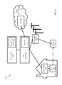
- FIG. 3 illustrates an example 300 of a Wi-Fi device 302 moving from radio node 304 to a different radio node 306 using centrally managed Wi-Fi, according to some embodiments.
- the Wi-Fi device 302 is streaming a session from a service provider's video on demand (VoD) service through the data plane 212 to the radio node 304 in the home 310 .
- VoD video on demand
- the management entity 118 When the Wi-Fi device 302 moves to outdoor Wi-Fi coverage using the radio node 306 , the management entity 118 maintains the Wi-Fi device 302 's session with the VoD 308 through the data plane 212 .
- the management entity 118 can provide DLNA interworking from the VoD 308 to the Wi-Fi device 302 via the control plane 210 , extending DLNA to the data plane 212 .
- Other approaches such as layer three approaches, often have a much more complex control plane and thus slower handover latency.
- DLNA can use IP Multicast (UPnP) for content discovery. Since IP Multicast is a local area network technology, DLNA service is limited to a Layer 2 broadcast domain only (e.g. limited to a house or a branch office).
- IP Broadcast/Multicast services can work transparently over a wide area.
- a user could be traveling and still connect to their DLNA-enabled Blue-Ray DVD player and watch content from a hotel (e.g., just as if the user is at home).
- FIG. 4 illustrates an example of a Wi-Fi device 402 in communication with radio node 406 printing to a Wi-Fi printer 404 supported by a different radio node 408 using centrally managed Wi-Fi, according to some embodiments.
- the Wi-Fi device 402 is connected to the radio node 406 providing outdoor Wi-Fi.
- the user of the Wi-Fi device 402 wants to print remotely to the home network provided by the radio node 408 for the user's home 410 .
- the WAG 102 provides simplified access via the data plane 212 , and the management entity 118 provides a global policy control to establish connectivity and mobility between the Wi-Fi device 402 and the Wi-Fi printer 404 .
- Native Multicast/Broadcast protocols like mDNS, Bonjour, NetBios, SMB2, etc. for home networking work transparently.
- Bonjour can be used by printers for printer discovery and printing.
- FIG. 5 illustrates an example 500 of parental control of a Wi-Fi device 502 using centrally managed Wi-Fi, according to some embodiments.
- a user e.g., a child
- Wi-Fi device 502 which has been configured using a parental control service so that the device can only access a special SSID where content filtering is performed using cloud-based parental control server 506 .
- the parental control server 506 is coupled to the radio node 504 via the data plane 212 , and the radio node 504 steers all flows from the Wi-Fi device 502 to the parental control server 506 .
- the centrally managed Wi-Fi allows the parental control service provider to enable a large number of user devices to use the parental control service provided by the parental control server 506 , cost-effectively and quickly.
- Mobile IP uses encapsulations and a number of different message exchanges, such as binding update exchanges, etc. Such encapsulations can also increase processing and signaling loads.
- the techniques described herein does not rely on any IP messaging, while providing fast handovers (e.g., in less than a hundred ms). Since the devices connect to the WAG using virtual Layer 2 tunnels (e.g., Layer 2 data routed via IP connections), when the device moves from one radio node to another, the WAG learns about this mobility by looking at the source MAC address of the Ethernet frames and matching them to the Layer 2 tunnel of the radio node. The WAG then updates the location of the device as being bound to the new radio node and directs all the traffic towards the new radio node where the device has moved to.
- Layer 2 tunnels e.g., Layer 2 data routed via IP connections
- the techniques described herein use MAC learning and MAC attachment to maintain Wi-Fi connections. Additionally, mobility encapsulation is not needed because the WAG keeps a binding of device and radio nodes the device is known to be (or have been) attached to. As the device moves from one radio node to another, the WAG updates the bindings accordingly based on MAC learning.
- the techniques use a signaling procedure called MAC learning (e.g., matching the device MAC to the MAC of the radio node). Such a procedure does not require additional messaging.
- the techniques described herein provide a scalable architecture for service provider applications. Since the Wi-Fi is centrally managed by one or more Wi-Fi access gateways, service providers can roll out new value-added services to all of its Wi-Fi clients. Network-based control of the architecture enables a common security framework for all managed Wi-Fi devices. For example, a Wi-Fi access gateway can update new threat vectors and/or reconfigure firewalls of the radio nodes rather than needing to independently manage or reconfigure each radio node.
- the Wi-Fi access layer can create high availability. For example, since service providers often have redundant data centers, the Layer 2 access layer is simple enough that it seldom fails, and the Wi-Fi access gateway can support full geographic redundancy.
- the simplification the Wi-Fi radio nodes as described herein facilitates remote configuration management and upgrades.
- the architecture can enable over subscription and efficient use of pooled resources in an elastic way for control plane and data plane shared across all the Wi-Fi radio nodes.
- network-based service control enables a third party developer ecosystem leveraging a rich API suite. For example, service providers can create a healthy ecosystem of application developers for niche value-added services.
- a “server,” “client,” “agent,” “module,” “interface,” and “host” is not software per se and includes at least some tangible, non-transitory hardware that is configured to execute computer readable instructions.
- the phrase “based on” does not imply exclusiveness—for example, if X is based on A, X can also be based on B, C, and/or D, . . . .
Landscapes
- Engineering & Computer Science (AREA)
- Computer Networks & Wireless Communication (AREA)
- Signal Processing (AREA)
- Computer Security & Cryptography (AREA)
- Mobile Radio Communication Systems (AREA)
Abstract
Description
Claims (13)
Priority Applications (2)
| Application Number | Priority Date | Filing Date | Title |
|---|---|---|---|
| US14/460,657 US9686808B2 (en) | 2013-08-15 | 2014-08-15 | Centrally managed WI-FI |
| US14/704,574 US9585186B2 (en) | 2013-08-15 | 2015-05-05 | System and method of providing advanced services in a virtual CPE deployment |
Applications Claiming Priority (2)
| Application Number | Priority Date | Filing Date | Title |
|---|---|---|---|
| US201361866354P | 2013-08-15 | 2013-08-15 | |
| US14/460,657 US9686808B2 (en) | 2013-08-15 | 2014-08-15 | Centrally managed WI-FI |
Related Child Applications (1)
| Application Number | Title | Priority Date | Filing Date |
|---|---|---|---|
| US14/704,574 Continuation-In-Part US9585186B2 (en) | 2013-08-15 | 2015-05-05 | System and method of providing advanced services in a virtual CPE deployment |
Publications (2)
| Publication Number | Publication Date |
|---|---|
| US20150049714A1 US20150049714A1 (en) | 2015-02-19 |
| US9686808B2 true US9686808B2 (en) | 2017-06-20 |
Family
ID=52466800
Family Applications (1)
| Application Number | Title | Priority Date | Filing Date |
|---|---|---|---|
| US14/460,657 Active US9686808B2 (en) | 2013-08-15 | 2014-08-15 | Centrally managed WI-FI |
Country Status (2)
| Country | Link |
|---|---|
| US (1) | US9686808B2 (en) |
| WO (1) | WO2015023940A2 (en) |
Cited By (2)
| Publication number | Priority date | Publication date | Assignee | Title |
|---|---|---|---|---|
| US20160112249A1 (en) * | 2014-10-15 | 2016-04-21 | Nimbus 9, Inc. | Rapid gateway swap |
| US11032708B2 (en) | 2018-09-26 | 2021-06-08 | International Business Machines Corporation | Securing public WLAN hotspot network access |
Families Citing this family (18)
| Publication number | Priority date | Publication date | Assignee | Title |
|---|---|---|---|---|
| US9654396B2 (en) * | 2014-01-15 | 2017-05-16 | Cisco Technology, Inc. | Controller-less peer-to-peer distributed switch |
| US20160050667A1 (en) | 2014-08-18 | 2016-02-18 | Samsung Electronics Co., Ltd. | Communication on licensed and unlicensed bands |
| US20160119166A1 (en) * | 2014-10-28 | 2016-04-28 | Electronics And Telecommunications Research Institute | Method and apparatus for providing gateway function |
| US10264515B2 (en) | 2014-12-22 | 2019-04-16 | Qualcomm Incorporated | Enhanced access network query protocol (ANQP) signaling to scale to support large numbers of service providers at an access point (AP) |
| EP3267760A4 (en) * | 2015-03-06 | 2018-11-07 | Kyocera Document Solutions Inc. | Image processing device and communication method |
| US10499328B2 (en) * | 2015-04-06 | 2019-12-03 | Cable Television Laboratories, Inc. | Self-organizing network (SON) with fast initial link setup (FILS) |
| CN105592145A (en) * | 2015-12-15 | 2016-05-18 | 艾迈斯按摩椅(上海)有限公司 | Stability-enhanced type remote network control system |
| CN106896729A (en) * | 2015-12-17 | 2017-06-27 | 美的集团股份有限公司 | The management method of family's group household electrical appliance, device and system |
| US10931477B2 (en) * | 2016-03-18 | 2021-02-23 | Plume Design, Inc. | Layer two network tunnels for Wi-Fi client bridging in a distributed Wi-Fi network |
| CN106603659B (en) * | 2016-12-13 | 2019-08-23 | 南京邮电大学 | A kind of intelligence manufacture private network data collection scheduling system |
| TWI611709B (en) * | 2016-12-30 | 2018-01-11 | 國立交通大學 | Network system with seamless handover mechanism, operation method and control apparatus thereof |
| WO2018182684A1 (en) * | 2017-03-31 | 2018-10-04 | Intel Corporation | A method for virtual carrier sensing that separates the control plane from the data plane |
| CN107911850B (en) * | 2017-11-28 | 2020-03-13 | 中国联合网络通信集团有限公司 | Transport network service establishing method and equipment |
| CN108024306B (en) * | 2017-12-05 | 2020-12-18 | 锐捷网络股份有限公司 | A kind of TCP connection management method and gateway device |
| CN112235849A (en) * | 2020-10-19 | 2021-01-15 | 展讯半导体(成都)有限公司 | Method, system, electronic device, and medium for identifying Wi-Fi hotspot type |
| CN113328873B (en) * | 2021-04-08 | 2022-05-27 | 新华三技术有限公司成都分公司 | Cloud management platform system and method for managing thin access point configuration |
| CN116319334A (en) * | 2021-12-03 | 2023-06-23 | 中兴通讯股份有限公司 | Application-based slice selection method, gateway, terminal and storage medium |
| US20230345241A1 (en) * | 2022-04-25 | 2023-10-26 | Apple Inc. | Brokered service discovery and connection management |
Citations (16)
| Publication number | Priority date | Publication date | Assignee | Title |
|---|---|---|---|---|
| US20050185635A1 (en) | 2003-07-30 | 2005-08-25 | C.L. Nagendra | Virtual service provider system and method for delivering media services to an end user |
| US6996628B2 (en) | 2000-04-12 | 2006-02-07 | Corente, Inc. | Methods and systems for managing virtual addresses for virtual networks |
| US20080072047A1 (en) | 2006-09-20 | 2008-03-20 | Futurewei Technologies, Inc. | Method and system for capwap intra-domain authentication using 802.11r |
| US20080198811A1 (en) | 2007-02-21 | 2008-08-21 | Qualcomm Incorporated | Wireless node search procedure |
| US20090086742A1 (en) | 2007-08-24 | 2009-04-02 | Rajat Ghai | Providing virtual services with an enterprise access gateway |
| US20090154415A1 (en) | 2007-12-18 | 2009-06-18 | Samsung Electronics Co. Ltd. | Scheduling apparatus and method for proportional resource allocation among mobile virtual network operators |
| US20090199281A1 (en) | 2008-01-31 | 2009-08-06 | Lucent Technologies Inc. | Method and apparatus for virtual wi-fi service with authentication and accounting control |
| US20100177752A1 (en) | 2009-01-12 | 2010-07-15 | Juniper Networks, Inc. | Network-based micro mobility in cellular networks using extended virtual private lan service |
| US20100192207A1 (en) | 2009-01-28 | 2010-07-29 | Gregory G. Raleigh | Virtual service provider systems |
| US20110274082A1 (en) * | 2010-05-04 | 2011-11-10 | Cisco Technology, Inc. | Maintaining Point of Presence at Access Switch for Roaming Clients in Distributed Wireless Controller System |
| US20130083691A1 (en) | 2011-10-04 | 2013-04-04 | Juniper Networks, Inc. | Methods and apparatus for a self-organized layer-2 enterprise network architecture |
| US20130083782A1 (en) | 2011-10-04 | 2013-04-04 | Juniper Networks, Inc. | Methods and apparatus for a scalable network with efficient link utilization |
| US20130287012A1 (en) * | 2012-04-27 | 2013-10-31 | Interdigital Patent Holdings, Inc. | Method and apparatus for optimizing proximity data path setup |
| US20140192795A1 (en) | 2013-01-09 | 2014-07-10 | Tabletop Media, LLC | Secure wireless network-based activation for table-side information and point-of-sale devices |
| US20140269535A1 (en) * | 2013-03-15 | 2014-09-18 | Cisco Technology, Inc. | Wireless system with split control plane and data plane |
| US20150235329A1 (en) | 2012-05-14 | 2015-08-20 | Michael Lu | Classified relation networking optimization platform in open wireless architecture (owa) mobile cloud terminal device |
-
2014
- 2014-08-15 US US14/460,657 patent/US9686808B2/en active Active
- 2014-08-15 WO PCT/US2014/051264 patent/WO2015023940A2/en not_active Ceased
Patent Citations (16)
| Publication number | Priority date | Publication date | Assignee | Title |
|---|---|---|---|---|
| US6996628B2 (en) | 2000-04-12 | 2006-02-07 | Corente, Inc. | Methods and systems for managing virtual addresses for virtual networks |
| US20050185635A1 (en) | 2003-07-30 | 2005-08-25 | C.L. Nagendra | Virtual service provider system and method for delivering media services to an end user |
| US20080072047A1 (en) | 2006-09-20 | 2008-03-20 | Futurewei Technologies, Inc. | Method and system for capwap intra-domain authentication using 802.11r |
| US20080198811A1 (en) | 2007-02-21 | 2008-08-21 | Qualcomm Incorporated | Wireless node search procedure |
| US20090086742A1 (en) | 2007-08-24 | 2009-04-02 | Rajat Ghai | Providing virtual services with an enterprise access gateway |
| US20090154415A1 (en) | 2007-12-18 | 2009-06-18 | Samsung Electronics Co. Ltd. | Scheduling apparatus and method for proportional resource allocation among mobile virtual network operators |
| US20090199281A1 (en) | 2008-01-31 | 2009-08-06 | Lucent Technologies Inc. | Method and apparatus for virtual wi-fi service with authentication and accounting control |
| US20100177752A1 (en) | 2009-01-12 | 2010-07-15 | Juniper Networks, Inc. | Network-based micro mobility in cellular networks using extended virtual private lan service |
| US20100192207A1 (en) | 2009-01-28 | 2010-07-29 | Gregory G. Raleigh | Virtual service provider systems |
| US20110274082A1 (en) * | 2010-05-04 | 2011-11-10 | Cisco Technology, Inc. | Maintaining Point of Presence at Access Switch for Roaming Clients in Distributed Wireless Controller System |
| US20130083691A1 (en) | 2011-10-04 | 2013-04-04 | Juniper Networks, Inc. | Methods and apparatus for a self-organized layer-2 enterprise network architecture |
| US20130083782A1 (en) | 2011-10-04 | 2013-04-04 | Juniper Networks, Inc. | Methods and apparatus for a scalable network with efficient link utilization |
| US20130287012A1 (en) * | 2012-04-27 | 2013-10-31 | Interdigital Patent Holdings, Inc. | Method and apparatus for optimizing proximity data path setup |
| US20150235329A1 (en) | 2012-05-14 | 2015-08-20 | Michael Lu | Classified relation networking optimization platform in open wireless architecture (owa) mobile cloud terminal device |
| US20140192795A1 (en) | 2013-01-09 | 2014-07-10 | Tabletop Media, LLC | Secure wireless network-based activation for table-side information and point-of-sale devices |
| US20140269535A1 (en) * | 2013-03-15 | 2014-09-18 | Cisco Technology, Inc. | Wireless system with split control plane and data plane |
Non-Patent Citations (1)
| Title |
|---|
| International Search Report and Written Opinion issued by the U.S. Patent and Trademark Office as International Searching Authority for International Application No. PCT/US14/51264 mailed Nov. 13, 2014 (12 pgs.). |
Cited By (3)
| Publication number | Priority date | Publication date | Assignee | Title |
|---|---|---|---|---|
| US20160112249A1 (en) * | 2014-10-15 | 2016-04-21 | Nimbus 9, Inc. | Rapid gateway swap |
| US10320605B2 (en) * | 2014-10-15 | 2019-06-11 | Nimbus 9, Inc. | Rapid gateway swap |
| US11032708B2 (en) | 2018-09-26 | 2021-06-08 | International Business Machines Corporation | Securing public WLAN hotspot network access |
Also Published As
| Publication number | Publication date |
|---|---|
| WO2015023940A2 (en) | 2015-02-19 |
| US20150049714A1 (en) | 2015-02-19 |
| WO2015023940A3 (en) | 2015-10-29 |
Similar Documents
| Publication | Publication Date | Title |
|---|---|---|
| US9686808B2 (en) | Centrally managed WI-FI | |
| US10098164B2 (en) | System and methods for providing virtualized cloud peering emulation services | |
| US9585186B2 (en) | System and method of providing advanced services in a virtual CPE deployment | |
| US20150327052A1 (en) | Techniques for Managing Network Access | |
| US12120557B2 (en) | Service delivery to a roaming user equipment using a software-defined networking (SDN) controller | |
| KR102664128B1 (en) | Enhanced NEF features, MEC and 5G integration | |
| US11197168B2 (en) | Systems and methods to augment the capacities and capabilities of cellular networks through an unmanned aerial vehicle network overlay | |
| Sun et al. | Integrating network function virtualization with SDR and SDN for 4G/5G networks | |
| EP2608617B1 (en) | System and method for resource management for operator services and internet | |
| US20160330077A1 (en) | WiFi VIRTUAL NETWORK SOLUTION | |
| CN106576117B (en) | Ultra-high-speed mobile network based on layer 2 switching | |
| US9860879B2 (en) | Virtual radio networks | |
| US20160105883A1 (en) | System and method for mobility enhanced wi-fi architecture | |
| CN114268975B (en) | Communication method and device | |
| CN117917908B (en) | Apparatus, method and computer program product for communication | |
| US11825384B2 (en) | Access agnostic delivery of broadcast, multicast, or unicast content | |
| Nakauchi et al. | Virtual cognitive base station: Enhancing software-based virtual router architecture with cognitive radio | |
| US20260067756A1 (en) | Seamless roaming solution for 5g capable user equipment (ue) in heterogeneous network environments | |
| US20260039546A1 (en) | Interworking of communication models between network functions | |
| US20250324351A1 (en) | Dynamic tuning of synchronization signal block periodicity, sib 2,3,4,5 broadcast periodicity and turn off dynamically to improve system performance & capacity | |
| Park et al. | Supporting Multi-interface Entities in Software-Defined Wireless Networks | |
| Elsadek et al. | SDWM: Software defined Wi-Fi mobility for smart IoT carriers | |
| Li et al. | Future cellular network architecture | |
| Elsadek et al. | SDWM: Software Defined Wi-Fi Mobility | |
| Zehl et al. | NxWLAN: Neighborhood eXtensible WLAN |
Legal Events
| Date | Code | Title | Description |
|---|---|---|---|
| AS | Assignment |
Owner name: PACIFIC WESTERN BANK, NORTH CAROLINA Free format text: SECURITY INTEREST;ASSIGNOR:BENU NETWORKS, INC.;REEL/FRAME:037391/0125 Effective date: 20151215 |
|
| AS | Assignment |
Owner name: BENU NETWORKS, INC., MASSACHUSETTS Free format text: ASSIGNMENT OF ASSIGNORS INTEREST;ASSIGNOR:GHAI, RAJAT;REEL/FRAME:042224/0717 Effective date: 20161214 |
|
| STCF | Information on status: patent grant |
Free format text: PATENTED CASE |
|
| AS | Assignment |
Owner name: BENU NETWORKS, INC., MASSACHUSETTS Free format text: RELEASE BY SECURED PARTY;ASSIGNOR:PACIFIC WESTERN BANK;REEL/FRAME:046645/0977 Effective date: 20180813 |
|
| MAFP | Maintenance fee payment |
Free format text: PAYMENT OF MAINTENANCE FEE, 4TH YR, SMALL ENTITY (ORIGINAL EVENT CODE: M2551); ENTITY STATUS OF PATENT OWNER: SMALL ENTITY Year of fee payment: 4 |
|
| AS | Assignment |
Owner name: CIENA CORPORATION, MARYLAND Free format text: MERGER;ASSIGNOR:BENU NETWORKS, INC.;REEL/FRAME:062296/0630 Effective date: 20221230 |
|
| FEPP | Fee payment procedure |
Free format text: ENTITY STATUS SET TO UNDISCOUNTED (ORIGINAL EVENT CODE: BIG.); ENTITY STATUS OF PATENT OWNER: LARGE ENTITY |
|
| MAFP | Maintenance fee payment |
Free format text: PAYMENT OF MAINTENANCE FEE, 8TH YEAR, LARGE ENTITY (ORIGINAL EVENT CODE: M1552); ENTITY STATUS OF PATENT OWNER: LARGE ENTITY Year of fee payment: 8 |