US9684115B1 - Light fixtures with waveguides - Google Patents
Light fixtures with waveguides Download PDFInfo
- Publication number
- US9684115B1 US9684115B1 US14/683,801 US201514683801A US9684115B1 US 9684115 B1 US9684115 B1 US 9684115B1 US 201514683801 A US201514683801 A US 201514683801A US 9684115 B1 US9684115 B1 US 9684115B1
- Authority
- US
- United States
- Prior art keywords
- waveguide
- housing
- light
- light fixture
- reflector
- Prior art date
- Legal status (The legal status is an assumption and is not a legal conclusion. Google has not performed a legal analysis and makes no representation as to the accuracy of the status listed.)
- Active, expires
Links
Images


Classifications
-
- G—PHYSICS
- G02—OPTICS
- G02B—OPTICAL ELEMENTS, SYSTEMS OR APPARATUS
- G02B6/00—Light guides; Structural details of arrangements comprising light guides and other optical elements, e.g. couplings
- G02B6/0001—Light guides; Structural details of arrangements comprising light guides and other optical elements, e.g. couplings specially adapted for lighting devices or systems
- G02B6/0011—Light guides; Structural details of arrangements comprising light guides and other optical elements, e.g. couplings specially adapted for lighting devices or systems the light guides being planar or of plate-like form
- G02B6/0033—Means for improving the coupling-out of light from the light guide
- G02B6/0035—Means for improving the coupling-out of light from the light guide provided on the surface of the light guide or in the bulk of it
- G02B6/0045—Means for improving the coupling-out of light from the light guide provided on the surface of the light guide or in the bulk of it by shaping at least a portion of the light guide
-
- F—MECHANICAL ENGINEERING; LIGHTING; HEATING; WEAPONS; BLASTING
- F21—LIGHTING
- F21V—FUNCTIONAL FEATURES OR DETAILS OF LIGHTING DEVICES OR SYSTEMS THEREOF; STRUCTURAL COMBINATIONS OF LIGHTING DEVICES WITH OTHER ARTICLES, NOT OTHERWISE PROVIDED FOR
- F21V7/00—Reflectors for light sources
- F21V7/0008—Reflectors for light sources providing for indirect lighting
- F21V7/0016—Reflectors for light sources providing for indirect lighting on lighting devices that also provide for direct lighting, e.g. by means of independent light sources, by splitting of the light beam, by switching between both lighting modes
-
- G—PHYSICS
- G02—OPTICS
- G02B—OPTICAL ELEMENTS, SYSTEMS OR APPARATUS
- G02B6/00—Light guides; Structural details of arrangements comprising light guides and other optical elements, e.g. couplings
- G02B6/0001—Light guides; Structural details of arrangements comprising light guides and other optical elements, e.g. couplings specially adapted for lighting devices or systems
- G02B6/0011—Light guides; Structural details of arrangements comprising light guides and other optical elements, e.g. couplings specially adapted for lighting devices or systems the light guides being planar or of plate-like form
- G02B6/0033—Means for improving the coupling-out of light from the light guide
- G02B6/0063—Means for improving the coupling-out of light from the light guide for extracting light out both the major surfaces of the light guide
-
- G—PHYSICS
- G02—OPTICS
- G02B—OPTICAL ELEMENTS, SYSTEMS OR APPARATUS
- G02B6/00—Light guides; Structural details of arrangements comprising light guides and other optical elements, e.g. couplings
- G02B6/0001—Light guides; Structural details of arrangements comprising light guides and other optical elements, e.g. couplings specially adapted for lighting devices or systems
- G02B6/0011—Light guides; Structural details of arrangements comprising light guides and other optical elements, e.g. couplings specially adapted for lighting devices or systems the light guides being planar or of plate-like form
- G02B6/0081—Mechanical or electrical aspects of the light guide and light source in the lighting device peculiar to the adaptation to planar light guides, e.g. concerning packaging
- G02B6/0086—Positioning aspects
- G02B6/0091—Positioning aspects of the light source relative to the light guide
-
- F—MECHANICAL ENGINEERING; LIGHTING; HEATING; WEAPONS; BLASTING
- F21—LIGHTING
- F21Y—INDEXING SCHEME ASSOCIATED WITH SUBCLASSES F21K, F21L, F21S and F21V, RELATING TO THE FORM OR THE KIND OF THE LIGHT SOURCES OR OF THE COLOUR OF THE LIGHT EMITTED
- F21Y2115/00—Light-generating elements of semiconductor light sources
- F21Y2115/10—Light-emitting diodes [LED]
-
- G—PHYSICS
- G02—OPTICS
- G02B—OPTICAL ELEMENTS, SYSTEMS OR APPARATUS
- G02B6/00—Light guides; Structural details of arrangements comprising light guides and other optical elements, e.g. couplings
- G02B6/0001—Light guides; Structural details of arrangements comprising light guides and other optical elements, e.g. couplings specially adapted for lighting devices or systems
- G02B6/0011—Light guides; Structural details of arrangements comprising light guides and other optical elements, e.g. couplings specially adapted for lighting devices or systems the light guides being planar or of plate-like form
- G02B6/0033—Means for improving the coupling-out of light from the light guide
- G02B6/005—Means for improving the coupling-out of light from the light guide provided by one optical element, or plurality thereof, placed on the light output side of the light guide
- G02B6/0055—Reflecting element, sheet or layer
-
- G—PHYSICS
- G02—OPTICS
- G02B—OPTICAL ELEMENTS, SYSTEMS OR APPARATUS
- G02B6/00—Light guides; Structural details of arrangements comprising light guides and other optical elements, e.g. couplings
- G02B6/0001—Light guides; Structural details of arrangements comprising light guides and other optical elements, e.g. couplings specially adapted for lighting devices or systems
- G02B6/0011—Light guides; Structural details of arrangements comprising light guides and other optical elements, e.g. couplings specially adapted for lighting devices or systems the light guides being planar or of plate-like form
- G02B6/0081—Mechanical or electrical aspects of the light guide and light source in the lighting device peculiar to the adaptation to planar light guides, e.g. concerning packaging
- G02B6/0085—Means for removing heat created by the light source from the package
Definitions
- Embodiments described herein relate generally to light fixtures, and more particularly to systems, methods, and devices for light-emitting diode (LED) fixtures with waveguides.
- LED light-emitting diode
- the glare from a light source can be caused by a lens, a diffuser, a reflector, and/or some other optical device of the light source.
- the disclosure relates to a curved waveguide having a length, a width, a height, and at least one side.
- the length can have at least one portion.
- a first portion of the at least one portion of the length can include a first curvature.
- the at least one side can be configured to receive light emitted by at least one light module disposed adjacent to the at least one side.
- the disclosure can generally relate to a light fixture.
- the light fixture can include a heat sink having at least one coupling feature, and at least one first light module thermally coupled to the heat sink.
- the light fixture can also include a curved waveguide having a length, a width, a height, and a first side.
- the length can include at least one waveguide portion.
- the at least one first light module can be disposed adjacent to the first side of the curved waveguide and can direct light into the curved waveguide.
- a first portion of the at least one waveguide portion of the length can have a first curvature.
- FIGS. 1A-1C show various views of a light fixture with a curved waveguide in accordance with certain example embodiments.
- FIGS. 2A-2C show various views of another light fixture with a curved waveguide in accordance with certain example embodiments.
- FIGS. 3A-3C show various views of yet another light fixture with a curved waveguide in accordance with certain example embodiments.
- FIGS. 4A-4C show various views of still another light fixture with a curved waveguide in accordance with certain example embodiments.
- FIGS. 5A-5C show various views of yet another light fixture with a curved waveguide in accordance with certain example embodiments.
- FIGS. 6A-6C show various views of still another light fixture with a curved waveguide in accordance with certain example embodiments.
- FIGS. 7A-7C show various views of yet another light fixture with a curved waveguide in accordance with certain example embodiments.
- FIGS. 8A and 8B show various views of still another light fixture with a curved waveguide in accordance with certain example embodiments.
- example embodiments discussed herein are directed to systems, apparatuses, and methods of light fixtures, modules, and other systems using curved waveguides. While the figures shown and described herein are directed to light fixtures using LED technologies, example curved waveguides can also be used to envelop other types of lighting technologies, including but not limited to fluorescent, halogen, and incandescent. Thus, the examples of curved waveguides described herein are not limited to LED technology.
- the light modules can be LED light strips (e.g., flexible, rigid), chip-on-board, discrete die, and/or any other suitable type of LED.
- the light sources of the light modules can be continuous, equidistant, or randomly disposed along a side of a curved waveguide.
- the light fixture can be any type of light fixture, including but not limited to a pendant, a troffer, a drop fixture, and a high bay.
- the term “curved waveguides” can refer to waveguides with one or more non-zero (e.g., non-planar, non-linear) curvatures.
- reflectors referred to herein can have one or more non-zero curvatures.
- a curvature of a reflector can be substantially the same as (and coincide with) a curvature of a curved waveguide.
- a curvature of a reflector and a curvature of a curved waveguide can be independent of each other.
- the curvature of some or all of a curved waveguide and/or a reflector can be zero (e.g., planar, linear).
- a “curve” of example curved waveguides is any intentional non-linear or non-planar contour to the waveguide or reflector.
- the curvature can be substantially constant (defined, for example, by a focal point) and/or vary over the length and/or width of an example curved waveguide or reflector.
- the curvature can be concave and/or convex.
- one or more portions of a curved waveguide are linear (planar) instead of curved.
- the shape, size, and position of the contours of an example curved waveguide or reflector can be specifically engineered and designed for a particular light fixture having one or more particular light modules positioned in particular locations.
- the contours of an example curved waveguide and/or reflector can have one or more of a number of benefits, including but not limited to reduced or eliminated glare, aesthetics, and flexible design.
- the various components of light fixtures using curved waveguides can be made of one or more of a number of suitable materials, including but not limited to plastic, glass, rubber, a polymer, and metal.
- a light fixture as defined herein can be a stand-alone fixture. Alternatively, a light fixture can actually be one of a number of light modules that are part of one or more of a number of fixtures.
- a light fixture (or components thereof) using example curved waveguides can be a new light fixture for a new installation, a new light fixture to replace an existing light fixture, or a retrofit of an existing light fixture.
- any component described in one or more figures herein can apply to any subsequent (or other) figures having the same label.
- the description for any component of a subsequent (or other) figure can be considered substantially the same as the corresponding component described with respect to a previous (or other) figure.
- a corresponding component shown and/or labeled in another figure can be inferred.
- the numbering scheme for the components in the figures herein parallel the numbering scheme for the components of previously or subsequently described figures in that each component is a three digit number having the identical last two digits.
- a user can be any person that interacts with a light fixture having an example curved waveguide.
- Examples of a user may include, but are not limited to, a consumer, an electrician, an engineer, a mechanic, a consultant, a contractor, a homeowner, and a manufacturer's representative.
- one or more of the components shown in the following figures may be omitted, added, repeated, and/or substituted. Accordingly, embodiments of light fixtures with curved waveguides should not be considered limited to the specific arrangements of components shown in such figures.
- Example embodiments of curved waveguides will be described more fully hereinafter with reference to the accompanying drawings, in which example embodiments of curved waveguides are shown. Curved waveguides may, however, be embodied in many different forms and should not be construed as limited to the example embodiments set forth herein. Rather, these example embodiments are provided so that this disclosure will be thorough and complete, and will fully convey the scope of curved waveguides to those of ordinary skill in the art. Like, but not necessarily the same, elements (also sometimes called components) in the various figures are denoted by like reference numerals for consistency.
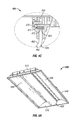
- FIGS. 1A-1C show various views of a light fixture 100 with a curved waveguide 120 in accordance with certain example embodiments Specifically, FIG. 1A shows a bottom-side perspective view of the light fixture 100 . FIG. 1B shows a side view of the light fixture 100 . FIG. 1C shows a cross-sectional side view of the light fixture 100 .
- the light fixture 100 can include a housing 130 , a power source 140 , a mounting bracket 180 , a heat sink 150 , at least one reflector (e.g., reflector 160 ), at least one light module 170 , and at least one curved waveguide 120 .
- the housing 130 can have one or more of a number of portions that form a cavity 190 .
- the housing 130 can include a top side 135 , a left side 134 , a right side 132 , a left-top side 133 , and a right-top side 131 .
- the housing 130 can also include an end cap 110 disposed on one or both ends of the housing 130 .
- One or more components of the light fixture 100 can be disposed within the cavity 190 of the housing 130 .
- One or more portions of the housing 130 can be made from a single piece, as from a mold. Alternatively, one or more portions of the housing 130 can be made from multiple pieces that are mechanically coupled to each other using one or more of a number of coupling means, including but not limited to epoxy, welding, fastening devices, compression fittings, and slotted fittings.
- the power source 140 can any device or series of devices that provide power and/or control to the light modules 170 .
- Examples of a power source 140 can include, but are not limited to, a driver, a ballast, and a battery.
- the power source 140 can generate power and/or receive power from an external source. In the latter case, the power source 140 can receive power in one form (e.g., alternating current) and generate (e.g., invert, convert, transform) power in another form (e.g., direct current).
- the mounting bracket 180 can be used to retain one or more other components of the light fixture 100 within the cavity 190 . For example, in this case, the mounting bracket 180 is used to hold the power source 140 and the heat sinks 150 in place.
- the one or more heat sinks 150 can be made of a thermally conductive material, allowing the heat sink 150 to absorb heat generated by one or more heat-generating components (e.g., the power source 140 , a light module 170 ). In other words, the heat sink 150 helps to prevent a heat-generating component of the light fixture 100 from overheating, leading to failure or a shortened life.
- a heat sink 150 can have one or more features that are used to position, retain, or otherwise control the placement of one or more components of the light fixture 100 within the cavity 190 .
- the heat sink 150 includes a feature 151 at its top end to couple to a portion of the mounting bracket 180 .
- the mounting bracket 180 can be used to hold the heat sink 150 in a certain position within the cavity 190 using the feature 151 .
- the heat sink 150 can include a feature 152 the retains and positions the light module 170 .
- the heat sink 150 can include a feature 153 to retain and position the curved waveguide 120 relative to the light module 170 .
- the main body 154 of the heat sink 150 in this case is disposed between feature 151 at one end of the heat sink 150 and feature 152 and feature 153 at the other end of the heat sink 150 .
- a light module 170 can have one or more of a number of configurations.
- the light module 170 includes one or more light sources 172 mounted on a light board 171 .
- One or more light modules 170 can be disposed adjacent to one or more edges (also called sides) of the curved waveguide 120 .
- the light module 170 is disposed adjacent to the right side of the curved waveguide 120 .
- light modules 170 can be disposed adjacent to the left and the right side of the curved waveguide 120 .
- light modules 170 can be disposed adjacent to the left side, the distal side, the proximate side, and the right side of the curved waveguide 120 .
- the optional reflector 160 can be made of and/or coated with a reflective material for reflecting light generated by the light source 172 of the light module 170 .
- the gap 162 can be an air gap that helps provide optical consistency to the light emitted by the light fixture 100 .
- the reflector 160 can have a curvature 161 along its length and/or width that is substantially similar (accounting for the gap 162 , if any) to the curvature 121 along the length and/or width of the curved waveguide 120 .
- the curved waveguide 120 guides, directs, and otherwise manipulates electromagnetic waves (e.g., light) generated by the light source 172 in the optical spectrum. Specifically, light generated by one or more light modules 170 is directed into one or more sides (in this case, the right side 123 ) of the curved waveguide 120 . Once inside the curved waveguide 120 , the light is reflected, refracted, diffused, and/or otherwise manipulated to exit the bottom surface 122 and/or the top surface 129 of the curved waveguide 120 in a desired pattern, intensity, and/or other dispersement characteristics.
- electromagnetic waves e.g., light
- the curved waveguide 120 can be one or more of a number of types of waveguides, including but not limited to a strip waveguide, a rib waveguide, a dielectric slab waveguide, a photonic crystal waveguide, and a segmented waveguide.
- the curved waveguide 120 can have any of a number (e.g., three, four, six, eight) of sides and form any of a number of shapes (e.g., triangular, pentagonal, octagonal, irregular) when viewed from above.
- the curved waveguide 120 has four sides (left side 124 , right side 123 , front side, and rear side) and has a rectangular shape when viewed from above.
- the curved waveguide 120 has a width 118 (for example, the distance along the curved waveguide 120 between the left side 124 and the right side 123 ), a thickness 119 (for example, the distance between the top surface 129 and the bottom surface 122 of the curved waveguide 120 ), and a length (for example, the distance along the curved waveguide 120 between the front side and the rear side).
- the length of the curved waveguide 120 can be substantially the same or different along its width 118 .
- the width 118 of the curved waveguide 120 can be substantially the same or different along its length.
- the thickness 119 at one point along the curved waveguide 120 can be substantially the same as, or different than, the thickness 119 at another point along the curved waveguide 120 .
- the curved waveguide 120 has at least one curvature (e.g., curvature 121 ) (also called a contour) along at least a portion of its length and/or width 118 .
- the curvature 121 can also be disposed along all or a portion of the thickness 119 (also called the height 119 ) of the waveguide.
- the thickness 119 of the curved waveguide 120 can be substantially constant or variable along the curvature 121 .
- the thickness 119 of curved waveguide 120 is substantially uniform along its length and width 118
- the curvature 121 of the curved waveguide 120 is substantially uniform along its length and width 118 .
- the curvature 121 is slightly concave and is substantially uniform along the width 118 of the curved waveguide 120 .
- FIGS. 2A-2C show various views of another light fixture 200 with a curved waveguide 220 in accordance with certain example embodiments.
- FIG. 2A shows a bottom-side perspective view of the light fixture 200 .
- FIG. 2B shows a cross-sectional side view of the light fixture 200 .
- FIG. 2C shows a detailed cross-sectional side view of a portion 201 of the light fixture 200 .
- the light fixture 200 of FIGS. 2A-2C is substantially the same as the light fixture 100 , except as described below.
- the light fixture 200 is symmetrical (left half and right half) along the length of the light fixture 200 .
- FIG. 2B shows this symmetry.
- Each half has a curved waveguide 220 that is substantially linear (planar) along its width 218 and length.
- the curvature 221 of the curved waveguide 220 is substantially zero along its width 218 and length.
- the curved waveguide 220 can simply be called a waveguide 220 .
- the light modules 270 are disposed just below the top side 235 of the housing 230 , slightly more than halfway toward the middle, and are adjacent to one side of the curved waveguide 220 . For example, as shown in FIG.
- the light module 270 is positioned adjacent to the left side 224 of the waveguide 220 .
- the other side (e.g., the right side 223 ) of the curved waveguide 220 abuts against (or comes near to abutting against) the distal end of the corresponding side (i.e., right side 232 and left side 234 ) of the housing 230 .
- a reflector 260 is disposed proximate (adjacent) to the top surface 229 of each curved waveguide 220 , leaving a gap 262 between the reflector 260 and the curved waveguide 220 on each half of the light fixture 200 .
- the curvature 261 of each reflector 260 can be substantially the same as the curvature 221 of the adjacent curved waveguide 220 .
- each end of the reflector 265 is located adjacent to a light module 270 .
- the reflector 265 can have its own curvature 266 .
- the reflector 265 has a left half and a right half. Each half of the reflector 265 in this example has a substantially identical curvature 266 .
- the power source 240 is positioned just below the top side 235 within the cavity 290 behind the reflector 265 .
- the light fixture 200 is an example where the curved waveguide 220 can actually be planar (not curved), but the benefits (e.g., reduced or no glare) of the curved waveguide 220 can be realized by virtue of the curved reflector 265 manipulating the light emitted through the waveguide 220 .
- FIGS. 3A-3C show various views of yet another light fixture 300 with a curved waveguide 320 in accordance with certain example embodiments.
- FIG. 3A shows a bottom-side perspective view of the light fixture 300 .
- FIG. 3B shows a cross-sectional side view of the light fixture 300 .
- FIG. 3C shows a detailed cross-sectional side view of a portion 301 of the light fixture 300 .
- the light fixture 300 of FIGS. 3A-3C is substantially the same as the light fixture 100 and the light fixture 200 , except as described below.
- the light fixture 300 has a v-shaped curved waveguide 320 , where the middle portion of the curved waveguide 320 has a curvature 312 A, while the rest of the curved waveguide 320 is substantially linear.
- a light module 270 is positioned adjacent to each of the left side 324 and the right side 323 of the “V” shape of the curved waveguide 320 , and light emitted by the light sources 372 is directed toward the center of the curved waveguide 320 , where the curvature 321 A is located.
- the rest of the curved waveguide 320 adjacent to the center portion can have a different curvature.
- the portion of the curved waveguide 320 to the left of the center can have curvature 321 B
- the portion of the curved waveguide 320 to the right of the center can have curvature 321 C.
- Curvature 321 B and curvature 321 C can be substantially the same as, or different than, each other. In this case, curvature 321 B and curvature 321 C are both substantially planar (flat). In this example, there is no reflector disposed adjacent to the curved waveguide 320 .
- a reflector 365 is symmetrically shaped about the center of the light fixture 300 in a length-wise direction, as shown in FIG. 3B . Aside from a linear (straight) middle portion, each half of the reflector 365 has a curvature 366 .
- the light fixture 300 is an example where the curved waveguide 220 can be partly curved and partly linear (not curved). In this case, the benefits of the curved waveguide 320 can be realized by virtue of the position and curvature 366 of the curved reflector 365 relative to the curved waveguide 320 .
- the curvature 321 A in this example is convex.
- the power source 340 is positioned just below the top side 335 within the cavity 390 behind the reflector 365 .
- FIGS. 4A-4C show various views of still another light fixture with a curved waveguide 420 in accordance with certain example embodiments.
- FIG. 4A shows a bottom-side perspective view of the light fixture 400 .
- FIG. 4B shows a cross-sectional side view of the light fixture 400 .
- FIG. 4C shows a detailed cross-sectional side view of a portion 401 of the light fixture 400 .
- the light fixture 400 of FIGS. 4A-4C is substantially the same as the light fixture 100 , the light fixture 200 , and the light fixture 300 , except as described below.
- the light fixture 400 is substantially symmetrical along its length.
- a reflector 460 is positioned proximate to the back side of the curved waveguide 420 , leaving a gap 462 between the reflector 460 and the curved waveguide 420 .
- the light modules 470 , and the left side 423 and the right side 424 of the curved waveguide 420 are disposed within heat sinks 450 mounted to an inner surface of the top side 435 of the housing 430 .
- An additional reflector 465 having a curvature 466 is disposed at each end of the light fixture 400 and is located at some distance from the curved waveguide 420 .
- the curvature 466 of each reflector 465 in this case is concave.
- the power source 440 is positioned just below the top side 435 within the cavity 490 behind the reflector 460 .
- FIGS. 5A-5C show various views of yet another light fixture 500 with a curved waveguide 520 in accordance with certain example embodiments.
- FIG. 5A shows a bottom-side perspective view of the light fixture 500 .
- FIG. 5B shows a cross-sectional side view of the light fixture 500 .
- FIG. 5C shows a detailed cross-sectional side view of a portion 501 of the light fixture 500 .
- the light fixture 500 of FIGS. 5A-5C is substantially the same as the light fixture 400 , except as described below.
- the power source 540 is disposed on the outer surface of the right-top side 531 , outside the housing 530 , instead of within the cavity 590 .
- the shape of the housing 530 differs, and so the curvature 566 of the reflectors 565 is slightly less concave.
- FIGS. 6A-6C show various views of still another light fixture 600 with a curved waveguide 620 in accordance with certain example embodiments.
- FIG. 6A shows a bottom-side perspective view of the light fixture 600 .
- FIG. 6B shows a bottom-side perspective view of the light fixture 600 without the end caps 610 .
- FIG. 6C shows a cross-sectional side view of the light fixture 600 .
- the light fixture 600 of FIGS. 6A-6C is substantially the same as the light fixtures described above, except as described below.
- the light fixture 600 has a waveguide 620 that is substantially straight or planar (the curvature 621 is approximately zero), has a length 617 and a height 618 , and hangs substantially vertically from the heat sink 650 mounted below the top side 635 of the housing 630 . If the waveguide 620 is not straight (planar), then the curvature 621 is non-zero. Similarly, the light modules 670 are mounted within the heat sink 650 adjacent to the top side 623 of the waveguide 620 . The light emitted by the light modules 670 is directed downward into the waveguide 620 .
- an optional diffuser 628 is disposed over the bottom side 624 of the waveguide 620 , where the bottom side 624 is opposite the top side 623 and the light modules 670 .
- a reflector 665 can be positioned on each side of the light module 600 .
- each reflector 665 is substantially straight (has a curvature 666 of approximately zero), and forms an acute angle with the waveguide 620 .
- the angle formed between the waveguide 620 and each reflector can also be perpendicular or obtuse.
- the curvature 666 of the reflectors 665 and the curvature 621 of the curved waveguide 620 are approximately zero, the angle between the reflectors 665 and the curved waveguide 620 can create some of the benefits (e.g., reduced or no glare) described herein.
- FIGS. 7A-7C show various views of yet another light fixture 700 with a curved waveguide 720 in accordance with certain example embodiments.
- FIG. 7A shows a bottom-side perspective view of the light fixture 700 .
- FIG. 7B shows a top-side perspective view of the light fixture 700 .
- FIG. 7C shows a top-side perspective view of a portion of the light fixture 700 .
- the light fixture 700 of FIGS. 7A-7C is substantially the same as the light fixture 100 of FIGS. 1A-1C , except as described below.
- the housing 730 of the light fixture 700 of FIGS. 7A-7C allows for uplighting and/or direct access to the reflector 760 .
- Uplighting is where light emitted through the curved waveguide 720 is directed upward (e.g., toward a ceiling), toward the housing 730 .
- the light emitted by the curved waveguide 720 for uplighting is directed in the opposite direction from light emitted by the curved waveguide 720 for downlighting.
- Light emitted by the curved waveguide 720 for downlighting travels downward (e.g., toward a floor), away from the housing 730 .
- the housing 730 of FIGS. 7A-7C has one or more gaps 799 .
- one gap 799 is disposed between the left side 734 and the left-top side 733 along the length of the housing 730 .
- Another gap 799 is disposed between the right side 732 and the right-top side (hidden from view) along the length of the housing 730 .
- the power source (hidden from view) and other such components of the light fixture 700 are disposed within a cavity formed by the front-top side 739 , the left-top side 733 , the right-top side, and the top side 735 of the housing 730 .
- the light modules (hidden from view) and the sides of the curved waveguide 720 are disposed within a different cavity formed by the right side 732 , the left side 734 , the front side 737 , and the rear side 736 .
- the light fixture 700 has no reflector, and so any light emitted through the top surface 729 of the curved waveguide 720 that is disposed in the gaps 799 is used for uplighting, while the remainder of the light can be emitted through the bottom surface 722 of the curved waveguide 720 as downlighting.
- the light fixture 700 has a reflector 760 , as described with respect to the light fixture 100 in FIGS. 1A-1C , any light emitted through the top surface 729 of the curved waveguide 720 is reflected back through the top surface 729 and emitted through the bottom surface 722 of the curved waveguide 720 as downlighting.
- the reflector 760 includes one or more features 798 that reflect some light while allowing some light to pass therethrough.
- a reflector 760 can have a number of apertures 798 that traverse through the wall of the reflector 760 . In this way, portions of the top surface 729 of the curved waveguide 720 are accessible in the gaps 799 , while the remainder of the gaps 799 are filled by the reflector 760 .
- the reflector 760 When the reflector 760 includes features 798 that reflect some light while allowing some light to pass therethrough, these features can be adjustable by a user. For example, if the features 798 are apertures, a user may be able to adjust the size of one or more apertures that are positioned in the gaps 799 .
- Another example of a feature 798 can include a transparent, non-reflective material.
- a reflector (such as any reflector described herein) can be disposed adjacent to the bottom surface 722 of the curved waveguide 720 to reduce or eliminate the amount of downlight while increasing the amount of uplight emitted by the light fixture 700 .
- FIGS. 8A and 8B show various views of still another light fixture 800 with a curved waveguide 820 in accordance with certain example embodiments. Specifically, FIGS. 8A and 8B each shows a bottom-side perspective view of the light fixture 800 .
- the light fixture 800 of FIGS. 8A and 8B is substantially the same as the light fixture 700 of FIGS. 7A-7C , except as described below.
- the gaps (hidden from view) in the housing 830 occupy all (or substantially all) of the area defined by the right side 832 , the left side 834 , the front side 837 , and the rear side 836 because the portion of the housing 830 that includes the left-top side 833 , the front-top side 839 , the right-top side (hidden from view), the rear-top side (hidden from view), the bottom-top side 897 , and the top side 835 are physically elevated from the area defined by the right side 832 , the left side 834 , the front side 837 , and the rear side 836 .
- housing portion separators 838 of the housing 830 can be used to separate the part of the housing 830 formed by the left-top side 833 , the front-top side 839 , the right-top side (hidden from view), the rear-top side (hidden from view), the bottom-top side 897 , and the top side 835 from the area defined by the right side 832 , the left side 834 , the front side 837 , and the rear side 836 .
- Examples of housing portion separators 838 can include, but are not limited to, standoffs (as shown in FIGS. 8A and 8B ), chains, and brackets.
- portions of the housing 830 can be made of and/or coated with one or more materials (e.g., reflective material) to help direct or otherwise manipulate uplight emitted through the top surface of the curved waveguide 820 .
- one or more portions of the housing 830 defined by the left-top side 833 , the front-top side 839 , the right-top side (hidden from view), the rear-top side (hidden from view), the bottom-top side 897 , and the top side 835 can have one or more features (e.g., contours, textures, curvatures) to help direct or otherwise manipulate uplight emitted through the top surface of the curved waveguide 820 .
- one or more features e.g., contours, textures, curvatures
- Example embodiments provide a number of benefits. Examples of such benefits include, but are not limited to, reduced glare, more consistent light output, and increased design flexibility for a light fixture. Example embodiments can also be used to generate uplight and/or downlight. In some cases, a user can control portions of one or more reflectors in example embodiments to control the amount of light (e.g., uplight, downlight) emitted by a light fixture.
Landscapes
- Physics & Mathematics (AREA)
- General Physics & Mathematics (AREA)
- Optics & Photonics (AREA)
- Engineering & Computer Science (AREA)
- General Engineering & Computer Science (AREA)
- Planar Illumination Modules (AREA)
- Non-Portable Lighting Devices Or Systems Thereof (AREA)
Abstract
Description
Claims (18)
Priority Applications (3)
| Application Number | Priority Date | Filing Date | Title |
|---|---|---|---|
| US14/683,801 US9684115B1 (en) | 2014-04-11 | 2015-04-10 | Light fixtures with waveguides |
| US15/614,159 US10001593B1 (en) | 2014-04-11 | 2017-06-05 | Light fixtures with waveguides |
| US16/011,428 US10401549B2 (en) | 2014-04-11 | 2018-06-18 | Light fixtures with waveguides |
Applications Claiming Priority (2)
| Application Number | Priority Date | Filing Date | Title |
|---|---|---|---|
| US201461978691P | 2014-04-11 | 2014-04-11 | |
| US14/683,801 US9684115B1 (en) | 2014-04-11 | 2015-04-10 | Light fixtures with waveguides |
Related Child Applications (1)
| Application Number | Title | Priority Date | Filing Date |
|---|---|---|---|
| US15/614,159 Continuation US10001593B1 (en) | 2014-04-11 | 2017-06-05 | Light fixtures with waveguides |
Publications (1)
| Publication Number | Publication Date |
|---|---|
| US9684115B1 true US9684115B1 (en) | 2017-06-20 |
Family
ID=59034069
Family Applications (3)
| Application Number | Title | Priority Date | Filing Date |
|---|---|---|---|
| US14/683,801 Active 2035-06-25 US9684115B1 (en) | 2014-04-11 | 2015-04-10 | Light fixtures with waveguides |
| US15/614,159 Active US10001593B1 (en) | 2014-04-11 | 2017-06-05 | Light fixtures with waveguides |
| US16/011,428 Active US10401549B2 (en) | 2014-04-11 | 2018-06-18 | Light fixtures with waveguides |
Family Applications After (2)
| Application Number | Title | Priority Date | Filing Date |
|---|---|---|---|
| US15/614,159 Active US10001593B1 (en) | 2014-04-11 | 2017-06-05 | Light fixtures with waveguides |
| US16/011,428 Active US10401549B2 (en) | 2014-04-11 | 2018-06-18 | Light fixtures with waveguides |
Country Status (1)
| Country | Link |
|---|---|
| US (3) | US9684115B1 (en) |
Cited By (8)
| Publication number | Priority date | Publication date | Assignee | Title |
|---|---|---|---|---|
| US10001593B1 (en) * | 2014-04-11 | 2018-06-19 | Cooper Technologies Company | Light fixtures with waveguides |
| WO2019020584A1 (en) * | 2017-07-25 | 2019-01-31 | Philips Lighting Holding B.V. | Light guide-based luminaire |
| WO2019067417A1 (en) * | 2017-09-26 | 2019-04-04 | Dialight Corporation | Diffuser with uplight |
| US20200182437A1 (en) * | 2018-12-11 | 2020-06-11 | Abl Ip Holding Llc | Luminaire with Improved Assembly, Installation, and Wireless Functionality |
| US10865958B2 (en) * | 2013-03-15 | 2020-12-15 | Ideal Industries Lighting Llc | Multi-waveguide LED luminaire with outward emission |
| US10921508B2 (en) | 2019-03-08 | 2021-02-16 | Abl Ip Holding Llc | Curved light guide assembly |
| US11231153B1 (en) * | 2020-07-22 | 2022-01-25 | ABU IP Holding LLC | Light fixture with improved waveguide control |
| EP4063717A1 (en) * | 2021-03-26 | 2022-09-28 | Zumtobel Lighting GmbH | Luminaire with front cooling function |
Citations (13)
| Publication number | Priority date | Publication date | Assignee | Title |
|---|---|---|---|---|
| US20040114342A1 (en) * | 2002-12-12 | 2004-06-17 | Toppoly Optoelectronics Corp. | Planar lighting structure |
| US20040114343A1 (en) * | 2002-12-14 | 2004-06-17 | Yi-Chun Ho | Backlight module having concave structure |
| US7334932B2 (en) * | 2004-04-24 | 2008-02-26 | Diehl Luftfahrt Elektronik Gmbh | LED-tube hybrid lighting arrangement |
| US20100208494A1 (en) * | 2009-02-17 | 2010-08-19 | Au Optronics Corp. | Light Guiding Device and Thin Display Comprising the Same |
| US20110242831A1 (en) * | 2010-03-31 | 2011-10-06 | Koito Manufacturing Co., Ltd. | Vehicular lamp |
| US8130340B2 (en) * | 2005-08-26 | 2012-03-06 | Tohoku University | Liquid crystal display and light guide plate |
| US20130094246A1 (en) * | 2011-10-14 | 2013-04-18 | Samsung Electronics Co., Ltd. | Backlight unit and display device having the same |
| US8454218B2 (en) * | 2010-05-20 | 2013-06-04 | Young Lighting Technology Inc. | Illuminating apparatus |
| US8454214B2 (en) * | 2009-06-05 | 2013-06-04 | Koito Manufacturing Co., Ltd. | Vehicular lamp LED-lit curved light guide lens |
| US8477259B2 (en) * | 2008-10-30 | 2013-07-02 | Hitachi Consumer Electronics Co., Ltd. | Liquid crystal display device |
| US8958029B2 (en) * | 2011-02-04 | 2015-02-17 | Kabushiki Kaisha Toshiba | Liquid crystal display device |
| US20150049509A1 (en) * | 2013-08-16 | 2015-02-19 | General Electric Company Global Research | Lighting System with Improved Illumination Distribution |
| US20160103269A1 (en) * | 2014-10-10 | 2016-04-14 | Koito Manufacturing Co., Ltd. | Illumination light guide |
Family Cites Families (6)
| Publication number | Priority date | Publication date | Assignee | Title |
|---|---|---|---|---|
| US1593A (en) * | 1840-05-08 | Improvement in the manner of constructing garden-hoes | ||
| US7384179B2 (en) * | 2006-01-18 | 2008-06-10 | Mitsubishi Electric Corporation | Planar light source unit and image display apparatus using the same |
| JP4640188B2 (en) * | 2006-01-18 | 2011-03-02 | 三菱電機株式会社 | Surface light source device |
| WO2012145293A2 (en) * | 2011-04-20 | 2012-10-26 | Rambus Inc. | Lighting assembly |
| US9081125B2 (en) * | 2011-08-08 | 2015-07-14 | Quarkstar Llc | Illumination devices including multiple light emitting elements |
| US9684115B1 (en) * | 2014-04-11 | 2017-06-20 | Cooper Technologies Company | Light fixtures with waveguides |
-
2015
- 2015-04-10 US US14/683,801 patent/US9684115B1/en active Active
-
2017
- 2017-06-05 US US15/614,159 patent/US10001593B1/en active Active
-
2018
- 2018-06-18 US US16/011,428 patent/US10401549B2/en active Active
Patent Citations (13)
| Publication number | Priority date | Publication date | Assignee | Title |
|---|---|---|---|---|
| US20040114342A1 (en) * | 2002-12-12 | 2004-06-17 | Toppoly Optoelectronics Corp. | Planar lighting structure |
| US20040114343A1 (en) * | 2002-12-14 | 2004-06-17 | Yi-Chun Ho | Backlight module having concave structure |
| US7334932B2 (en) * | 2004-04-24 | 2008-02-26 | Diehl Luftfahrt Elektronik Gmbh | LED-tube hybrid lighting arrangement |
| US8130340B2 (en) * | 2005-08-26 | 2012-03-06 | Tohoku University | Liquid crystal display and light guide plate |
| US8477259B2 (en) * | 2008-10-30 | 2013-07-02 | Hitachi Consumer Electronics Co., Ltd. | Liquid crystal display device |
| US20100208494A1 (en) * | 2009-02-17 | 2010-08-19 | Au Optronics Corp. | Light Guiding Device and Thin Display Comprising the Same |
| US8454214B2 (en) * | 2009-06-05 | 2013-06-04 | Koito Manufacturing Co., Ltd. | Vehicular lamp LED-lit curved light guide lens |
| US20110242831A1 (en) * | 2010-03-31 | 2011-10-06 | Koito Manufacturing Co., Ltd. | Vehicular lamp |
| US8454218B2 (en) * | 2010-05-20 | 2013-06-04 | Young Lighting Technology Inc. | Illuminating apparatus |
| US8958029B2 (en) * | 2011-02-04 | 2015-02-17 | Kabushiki Kaisha Toshiba | Liquid crystal display device |
| US20130094246A1 (en) * | 2011-10-14 | 2013-04-18 | Samsung Electronics Co., Ltd. | Backlight unit and display device having the same |
| US20150049509A1 (en) * | 2013-08-16 | 2015-02-19 | General Electric Company Global Research | Lighting System with Improved Illumination Distribution |
| US20160103269A1 (en) * | 2014-10-10 | 2016-04-14 | Koito Manufacturing Co., Ltd. | Illumination light guide |
Cited By (14)
| Publication number | Priority date | Publication date | Assignee | Title |
|---|---|---|---|---|
| US10865958B2 (en) * | 2013-03-15 | 2020-12-15 | Ideal Industries Lighting Llc | Multi-waveguide LED luminaire with outward emission |
| US10401549B2 (en) * | 2014-04-11 | 2019-09-03 | Eaton Intelligent Power Limited | Light fixtures with waveguides |
| US20180364410A1 (en) * | 2014-04-11 | 2018-12-20 | Eaton Intelligent Power Limited | Light Fixtures with Waveguides |
| US10001593B1 (en) * | 2014-04-11 | 2018-06-19 | Cooper Technologies Company | Light fixtures with waveguides |
| CN110914591A (en) * | 2017-07-25 | 2020-03-24 | 昕诺飞控股有限公司 | Light guide based luminaire |
| US20200192020A1 (en) * | 2017-07-25 | 2020-06-18 | Signify Holding B.V. | Light guide-based luminaire |
| WO2019020584A1 (en) * | 2017-07-25 | 2019-01-31 | Philips Lighting Holding B.V. | Light guide-based luminaire |
| US10443814B2 (en) | 2017-09-26 | 2019-10-15 | Dialight Corporation | Diffuser with uplight |
| WO2019067417A1 (en) * | 2017-09-26 | 2019-04-04 | Dialight Corporation | Diffuser with uplight |
| US20200182437A1 (en) * | 2018-12-11 | 2020-06-11 | Abl Ip Holding Llc | Luminaire with Improved Assembly, Installation, and Wireless Functionality |
| US11098880B2 (en) * | 2018-12-11 | 2021-08-24 | Abl Ip Holding Llc | Luminaire with improved assembly, installation, and wireless functionality |
| US10921508B2 (en) | 2019-03-08 | 2021-02-16 | Abl Ip Holding Llc | Curved light guide assembly |
| US11231153B1 (en) * | 2020-07-22 | 2022-01-25 | ABU IP Holding LLC | Light fixture with improved waveguide control |
| EP4063717A1 (en) * | 2021-03-26 | 2022-09-28 | Zumtobel Lighting GmbH | Luminaire with front cooling function |
Also Published As
| Publication number | Publication date |
|---|---|
| US10001593B1 (en) | 2018-06-19 |
| US10401549B2 (en) | 2019-09-03 |
| US20180364410A1 (en) | 2018-12-20 |
Similar Documents
| Publication | Publication Date | Title |
|---|---|---|
| US10401549B2 (en) | Light fixtures with waveguides | |
| EP3097348B1 (en) | Lighting device and luminaire | |
| CA2879388C (en) | Omni-directional reflector comprising a frusto-conical surface for a light-emitting diode | |
| EP2998638B1 (en) | Method and system for led lamp incorporating internal optics for specific light distribution | |
| CN105339731A (en) | Edgelit multi-panel lighting system | |
| US10520663B2 (en) | Illumination system based on active and passive illumination devices | |
| EP3221735B1 (en) | Wall wash luminaire with light guide and optical element therefore | |
| JP7229331B2 (en) | interconnectable light guide tiles | |
| CN108278540B (en) | Lighting device | |
| EP2726780B1 (en) | Light guide | |
| EP2811217B1 (en) | Illumination apparatus | |
| US20160305618A1 (en) | Luminaire | |
| JP6241601B2 (en) | Lighting device | |
| JP6134908B2 (en) | lighting equipment | |
| JP2012114081A (en) | Glare-reduced lighting system | |
| US20160223164A1 (en) | Wall washer lighting system with light emitter, optical lens and reflector | |
| JP6525974B2 (en) | Lighting apparatus and lighting apparatus | |
| CN113710952A (en) | Light emitting apparatus | |
| WO2020229481A1 (en) | Reduced glare lighting | |
| KR101549028B1 (en) | Lighting apparatus | |
| US20150233543A1 (en) | Shaped indirect luminaire | |
| WO2015172013A1 (en) | Method and system for led lamp incorporating internal optics for extended light distribution | |
| KR20130023974A (en) | Lighting equipment | |
| KR20090094718A (en) | Asymmetric indirect lighting collimator | |
| CN105202395A (en) | Lighting device |
Legal Events
| Date | Code | Title | Description |
|---|---|---|---|
| AS | Assignment |
Owner name: COOPER TECHNOLOGIES COMPANY, TEXAS Free format text: ASSIGNMENT OF ASSIGNORS INTEREST;ASSIGNORS:CARNEY, ANTHONY JAMES;LEWIS, PAUL WAYNE;LASO, JOSE ANTONIO;REEL/FRAME:035645/0383 Effective date: 20150410 |
|
| FEPP | Fee payment procedure |
Free format text: PAYOR NUMBER ASSIGNED (ORIGINAL EVENT CODE: ASPN); ENTITY STATUS OF PATENT OWNER: LARGE ENTITY |
|
| STCF | Information on status: patent grant |
Free format text: PATENTED CASE |
|
| AS | Assignment |
Owner name: EATON INTELLIGENT POWER LIMITED, IRELAND Free format text: ASSIGNMENT OF ASSIGNORS INTEREST;ASSIGNOR:COOPER TECHNOLOGIES COMPANY;REEL/FRAME:048207/0819 Effective date: 20171231 |
|
| AS | Assignment |
Owner name: EATON INTELLIGENT POWER LIMITED, IRELAND Free format text: CORRECTIVE ASSIGNMENT TO CORRECT THE COVER SHEET TO REMOVE APPLICATION NO. 15567271 PREVIOUSLY RECORDED ON REEL 048207 FRAME 0819. ASSIGNOR(S) HEREBY CONFIRMS THE ASSIGNMENT;ASSIGNOR:COOPER TECHNOLOGIES COMPANY;REEL/FRAME:048655/0114 Effective date: 20171231 |
|
| AS | Assignment |
Owner name: SIGNIFY HOLDING B.V., NETHERLANDS Free format text: ASSIGNMENT OF ASSIGNORS INTEREST;ASSIGNOR:EATON INTELLIGENT POWER LIMITED;REEL/FRAME:052681/0475 Effective date: 20200302 |
|
| MAFP | Maintenance fee payment |
Free format text: PAYMENT OF MAINTENANCE FEE, 4TH YEAR, LARGE ENTITY (ORIGINAL EVENT CODE: M1551); ENTITY STATUS OF PATENT OWNER: LARGE ENTITY Year of fee payment: 4 |
|
| AS | Assignment |
Owner name: SIGNIFY HOLDING B.V., NETHERLANDS Free format text: CORRECTIVE ASSIGNMENT TO CORRECT THE APPLICATION NUMBERS 12183490, 12183499, 12494944, 12961315, 13528561, 13600790, 13826197, 14605880, 15186648, RECORDED IN ERROR PREVIOUSLY RECORDED ON REEL 052681 FRAME 0475. ASSIGNOR(S) HEREBY CONFIRMS THE ASSIGNMENT;ASSIGNOR:EATON INTELLIGENT POWER LIMITED;REEL/FRAME:055965/0721 Effective date: 20200302 |
|
| MAFP | Maintenance fee payment |
Free format text: PAYMENT OF MAINTENANCE FEE, 8TH YEAR, LARGE ENTITY (ORIGINAL EVENT CODE: M1552); ENTITY STATUS OF PATENT OWNER: LARGE ENTITY Year of fee payment: 8 |