US9680935B2 - Grid gateway and transmission tower management system with multiple grid gateways - Google Patents
Grid gateway and transmission tower management system with multiple grid gateways Download PDFInfo
- Publication number
- US9680935B2 US9680935B2 US14/527,096 US201414527096A US9680935B2 US 9680935 B2 US9680935 B2 US 9680935B2 US 201414527096 A US201414527096 A US 201414527096A US 9680935 B2 US9680935 B2 US 9680935B2
- Authority
- US
- United States
- Prior art keywords
- grid
- wireless module
- environment parameters
- gateways
- wan
- Prior art date
- Legal status (The legal status is an assumption and is not a legal conclusion. Google has not performed a legal analysis and makes no representation as to the accuracy of the status listed.)
- Expired - Fee Related, expires
Links
Images


Classifications
-
- H—ELECTRICITY
- H04—ELECTRIC COMMUNICATION TECHNIQUE
- H04L—TRANSMISSION OF DIGITAL INFORMATION, e.g. TELEGRAPHIC COMMUNICATION
- H04L67/00—Network arrangements or protocols for supporting network services or applications
- H04L67/01—Protocols
- H04L67/12—Protocols specially adapted for proprietary or special-purpose networking environments, e.g. medical networks, sensor networks, networks in vehicles or remote metering networks
-
- H—ELECTRICITY
- H04—ELECTRIC COMMUNICATION TECHNIQUE
- H04L—TRANSMISSION OF DIGITAL INFORMATION, e.g. TELEGRAPHIC COMMUNICATION
- H04L41/00—Arrangements for maintenance, administration or management of data switching networks, e.g. of packet switching networks
- H04L41/08—Configuration management of networks or network elements
- H04L41/085—Retrieval of network configuration; Tracking network configuration history
- H04L41/0853—Retrieval of network configuration; Tracking network configuration history by actively collecting configuration information or by backing up configuration information
-
- H—ELECTRICITY
- H04—ELECTRIC COMMUNICATION TECHNIQUE
- H04W—WIRELESS COMMUNICATION NETWORKS
- H04W52/00—Power management, e.g. Transmission Power Control [TPC] or power classes
- H04W52/02—Power saving arrangements
- H04W52/0209—Power saving arrangements in terminal devices
- H04W52/0212—Power saving arrangements in terminal devices managed by the network, e.g. network or access point is leader and terminal is follower
- H04W52/0216—Power saving arrangements in terminal devices managed by the network, e.g. network or access point is leader and terminal is follower using a pre-established activity schedule, e.g. traffic indication frame
-
- H04W4/006—
-
- H—ELECTRICITY
- H04—ELECTRIC COMMUNICATION TECHNIQUE
- H04W—WIRELESS COMMUNICATION NETWORKS
- H04W4/00—Services specially adapted for wireless communication networks; Facilities therefor
- H04W4/30—Services specially adapted for particular environments, situations or purposes
- H04W4/38—Services specially adapted for particular environments, situations or purposes for collecting sensor information
-
- H—ELECTRICITY
- H04—ELECTRIC COMMUNICATION TECHNIQUE
- H04W—WIRELESS COMMUNICATION NETWORKS
- H04W84/00—Network topologies
- H04W84/02—Hierarchically pre-organised networks, e.g. paging networks, cellular networks, WLAN [Wireless Local Area Network] or WLL [Wireless Local Loop]
- H04W84/10—Small scale networks; Flat hierarchical networks
- H04W84/12—WLAN [Wireless Local Area Networks]
-
- H—ELECTRICITY
- H04—ELECTRIC COMMUNICATION TECHNIQUE
- H04W—WIRELESS COMMUNICATION NETWORKS
- H04W84/00—Network topologies
- H04W84/18—Self-organising networks, e.g. ad-hoc networks or sensor networks
-
- H—ELECTRICITY
- H04—ELECTRIC COMMUNICATION TECHNIQUE
- H04W—WIRELESS COMMUNICATION NETWORKS
- H04W88/00—Devices specially adapted for wireless communication networks, e.g. terminals, base stations or access point devices
- H04W88/16—Gateway arrangements
-
- Y—GENERAL TAGGING OF NEW TECHNOLOGICAL DEVELOPMENTS; GENERAL TAGGING OF CROSS-SECTIONAL TECHNOLOGIES SPANNING OVER SEVERAL SECTIONS OF THE IPC; TECHNICAL SUBJECTS COVERED BY FORMER USPC CROSS-REFERENCE ART COLLECTIONS [XRACs] AND DIGESTS
- Y02—TECHNOLOGIES OR APPLICATIONS FOR MITIGATION OR ADAPTATION AGAINST CLIMATE CHANGE
- Y02D—CLIMATE CHANGE MITIGATION TECHNOLOGIES IN INFORMATION AND COMMUNICATION TECHNOLOGIES [ICT], I.E. INFORMATION AND COMMUNICATION TECHNOLOGIES AIMING AT THE REDUCTION OF THEIR OWN ENERGY USE
- Y02D30/00—Reducing energy consumption in communication networks
- Y02D30/70—Reducing energy consumption in communication networks in wireless communication networks
-
- Y—GENERAL TAGGING OF NEW TECHNOLOGICAL DEVELOPMENTS; GENERAL TAGGING OF CROSS-SECTIONAL TECHNOLOGIES SPANNING OVER SEVERAL SECTIONS OF THE IPC; TECHNICAL SUBJECTS COVERED BY FORMER USPC CROSS-REFERENCE ART COLLECTIONS [XRACs] AND DIGESTS
- Y04—INFORMATION OR COMMUNICATION TECHNOLOGIES HAVING AN IMPACT ON OTHER TECHNOLOGY AREAS
- Y04S—SYSTEMS INTEGRATING TECHNOLOGIES RELATED TO POWER NETWORK OPERATION, COMMUNICATION OR INFORMATION TECHNOLOGIES FOR IMPROVING THE ELECTRICAL POWER GENERATION, TRANSMISSION, DISTRIBUTION, MANAGEMENT OR USAGE, i.e. SMART GRIDS
- Y04S40/00—Systems for electrical power generation, transmission, distribution or end-user application management characterised by the use of communication or information technologies, or communication or information technology specific aspects supporting them
- Y04S40/18—Network protocols supporting networked applications, e.g. including control of end-device applications over a network
Definitions
- the present invention relates to transmission tower management systems, and, more particularly, to a grid gateway and a transmission tower management system having a plurality of grid gateways.
- the voltage transmission lines will pass the urban, mountain, coastal areas, and so on.
- the different natural disasters in the various areas will result in the damage of transmission lines accidentally.
- the climate of high moist and salinity may make the transmission lines age more easily.
- the mudslides may make the depletion of the soil near the power tower by the earthquake and heavy rain, and that will make the ground slide and make the buildings tilt or even collapse.
- the power towers are mainly built in the urban, mountain, and costal areas, these areas don't have as enough infrastructures of interact communication as metro areas has.
- the distance between the tower to tower is usually too long and doesn't has any wireless network.
- the monitoring data can not be efficiently transmitted back to the remote monitoring center through a single network system. That makes a big restriction of the data communication and transmission.
- the present invention provides a grid gateway and a transmission tower management system having a plurality of grid gateways to build a management and monitoring system to overcome the restrictions of topography and communication.
- the present invention provides a transmission tower system, comprising: a plurality of sensors provided on extra high voltage transmission lines of transmission towers to collect environment parameters around the extra high voltage transmission lines; a plurality of grid gateways provided on the transmission towers to receive the environment parameters from the sensors within a wireless transmission range of the grid gateways, the grid gateways being connected to one another to form a mesh network, and the environment parameters being transmitted to one of the grid gateways through the mesh network; and a server connected to at least one of the grid gateways to receive the environment parameters and save the environment parameters in a database of the server.
- the present vention further provides a grid gateway, comprising: a LAN wireless module that receives environment parameters collected by sensors disposed on extra high voltage transmission lines of transmission towers; a WAN wireless module connected to a WAN wireless module provided on grid gateways of another transmission tower to form a mesh network; a packet format converting module connected to the LAN wireless module to acquire the environment parameters and convert the environment parameters from a LAN packet format of the LAN wireless module to a WAN packet format of the WAN wireless module; and a router module that chooses an optimal transmission route within the mesh network, wherein the WAN wireless module transmits the environment parameters in the WAN packet format through the optimal transmission route to one of the grid gateways within the mesh network.
- the grid gateway and the transmission tower management system comprising a plurality of grid gateways according to the present invention are capable for wireless transmission in wide and local areas.
- the present invention can overcome the restrictions of the topography and communication.
- the environment parameters can be transmitted to the back-end management center efficiently.
- the operation state of the transmission towers and the grid gateway network can be managed and monitored simultaneously and ensure the safety of the transmission towers and the grid gateway network.
- FIG. 1A is a schematic view of a transmission tower management system having a plurality of grid gateways according to the present invention
- FIG. 1B is a schematic view illustrating the connection condition between any two of the transmission towers in accordance with FIG. 1A ;
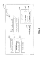
- FIG. 2 is a schematic view of a grid gateway according to the present invention.
- FIG. 1A is a schematic view of a transmission tower management system having a plurality of grid gateways according to the present invention.
- FIG. 1B is a schematic view illustrating the connection condition between any two of the transmission towers in accordance with FIG. 1A .
- FIG. 2 is a schematic view of a grid gateway 200 according to the present invention.
- the grid gateway 200 is provided directly on a transmission tower 12 or in the industrial distribution box on the transmission tower 12 .
- the industrial distribution box can prevent the damage caused by long term exposure.
- the grid gateway 200 comprises a local area network (LAN) wireless module 210 , a wide area network (WAN) wireless module 230 , a packet format converting module 220 , and a router module 240 .
- LAN local area network
- WAN wide area network
- the LAN wireless module 210 is used to connect a plurality of sensors 14 on extra high voltage transmission lines 13 provided on the transmission tower 12 .
- the connection is built by a wireless method.
- the connection between the LAN wireless module 210 and the sensors 14 build the first (e.g., ZigBee) wireless connection 16 in the wireless sensing network protocol (e.g., ZigBee).
- the LAN wireless module 210 is specifically the ZigBee wireless sensor network (802.15.4 WPAN) transmission module.
- the plurality of sensors 14 carry the same ZigBee wireless sensing network transmission module to build the first wireless connection 16 with the LAN wireless module 210 .
- the plurality of sensors 14 are provided with a variety of sensing components, such as a temperature sensor, a humidity sensor, a rain gauge, an anemometer, an illuminometer, a 3-axis accelerometer, and so on.
- the environment parameters such as temperature, temperature of the extra high voltage transmission lines, humidity, rainfall, illuminance, gravity acceleration, and so on, can be acquired. The environment parameters can then be transmitted to the grid gateways 200 through the first wireless connection 16 .
- the WAN wireless module 230 of the grid gateway 200 has a different wireless network protocol from the LAN wireless module 210 .
- the WAN wireless module 230 uses IEEE 802.11 protocol.
- the specification of the protocol can be used to make a base station connect to a polarity of subscriber stations with each other and build a many-many mesh network.
- the transmission towers can build the mesh network which has the second (e.g., IEEE 802.11) wireless connection 17 via the WAN wireless module 230 of the respective grid gateways 200 . It means that each grid gateway is applied as a base station and subscriber station simultaneously. In an embodiment, as shown in FIG.
- the mesh network is mainly built with the transmission towers 126 .
- the transmission range of the mesh network is the wireless transmission range of the grid gateways 18 of the transmission towers 126 .
- the transmission towers 122 , 123 and 125 can build the second connection 17 with the transmission tower 126 respectively.
- the transmission towers 121 and 124 are outside the wireless transmission range of the grid gateways 18 , so the connection to the transmission tower 126 cannot be built.
- the transmission towers 121 and 124 can build the connection with other transmission towers inside the transmission range. Therefore, the grid gateways of each transmission tower can build connection to the other transmission towers inside the wireless transmission range and form a large mesh network accordingly.
- the WAN wireless module is specifically an industrial router with WiFi function, and the transmission distance can reach to 2 kilometer.
- the grid gateway 200 then can build the second connection 17 to the server 1 .
- the data can further be transmitted to the server 11 and save in the database of server 11 .
- the packet format converting module 220 is connected to the LAN wireless module 210 for acquiring the environment parameters.
- the packet format converting module 220 is a software program.
- the packet format converting module 220 after receiving the environment parameters, converts the environment parameters from the LAN packet format of the LAN package wireless module 210 to the WAN packet format of the WAN wireless module 230 .
- the packet format of environment parameters will be converted from ZigBee protocol to IEEE 802.11 protocol.
- the environment parameters After received by the sensors 14 of the grid gateways 200 , the environment parameters will be transmitted to the server 11 .
- the router module 240 When the grid gateway 200 receives and transmits the environment parameters to the server 11 , the router module 240 will firstly choose an optimal route within the mesh network by an algorithm, and the WAN wireless module 230 transmits the environment parameters in the packet format of IEEE 802.11 protocol through the optimal route to one of the grid gateways 200 within the mesh network.
- the environment parameters will be transmitted to the nearest one of the grid gateways to the server 11 , as the transmission tower shown in FIG. 1A .
- the software program, or the router module 240 will determine the optimal transmission route according to the quality of service (QoS), the time to live (TTL), or the priority of traffic between the grid gateways within the mesh network. For example, to choose the route of the better QoS, short TTL, or use the enhanced distributed channel access (EDCA) based on competition, HCF controlled channel access (HCCA) based on non-competition, an so on techniques to control the each traffic has different priority or the bandwidth resource and so on, and choose the optimal route accordingly.
- QoS quality of service
- TTL time to live
- EDCA enhanced distributed channel access
- HCCA HCF controlled channel access
- the grid gateway 200 further includes a power unit 260 for supplying the electric power to the grid gateway 200 .
- the power unit 260 includes a solar panel 262 and a charging module 264 .
- the solar panel 262 can convert the solar light to electric power and stores the electric power in the charging module 264 such that the electric power can be supplied to the grid gateway 200 at any time.
- the charging module 264 is a secondary battery.
- a grid gateway 200 further includes at least one monitoring unit 270 to collect the environment parameters around the arid gateway 200 , including temperature, temperature of extra high voltage transmission lines, humidity, rainfall, illuminance, gravity acceleration, and so on.
- the grid gateway 200 can be provided with a plurality of different monitoring unit 270 to acquire different environment parameters for different propose.
- 3-axis accelerometer, temperature sensor, humidity sensor, rain gauge, anemometer, and so on can be provided.
- the grid gateway 200 further includes a task scheduling module 250 .
- the task scheduling module 250 is a software program, which can be used to set the grid gateway 200 to execute the command from the software on schedule time and can repeatedly execute the command periodically.
- the WAN wireless module 230 within the grid gateway 200 can be set to turn on at 10:00 a.m. everyday, and to turn off at 10:10 a.m. everyday. In other words, the WAN wireless module 230 only works 10 minutes everyday, and the transmission of environment parameters will be complete in the 10 minutes routinely. Thus, because the WAN wireless module 230 is kept in a turning-off state for a long time to reduce the connection state time, the power can be saved.
- the grid gateway 200 can build a transmission tower, which includes a plurality of sensors 14 , a plurality of grid gateways 200 , and a server 11 .
- the plurality of sensors 14 are provided on the extra high voltage transmission lines 13 between the plurality of transmission towers 12 .
- sensors 14 are temperature sensors, humidity sensors, rain gauges, anemometers, illuminometer, or 3-axis accelerometers. Therefore, the environment parameters around the extra high voltage transmission lines 13 can be acquired, for example, temperature, temperature of extra high voltage transmission lines 13 , humidity, rainfall, wind direction, wind speed, illuminance, gravity acceleration, and so on.
- the grid gateways 200 are provided on a plurality of transmission towers, and have to be disposed within the corresponding wireless transmission range.
- the grid gateways 200 can then build a first connection 16 in ZigBee protocol to the sensors 14 within the wireless transmission range to receive the environment parameters which are collected by sensors 14 .
- the mesh network is formed by the connection between grid gateways to each other via IEEE 802.11 protocol.
- the grid gateways 200 communicates with one another through the second connection 17 , and at least one of grid gateways 200 can connect to the server 11 through the second connection 17 .
- the environment parameters acquired by the sensors 14 can be transmitted to the grid gateways 200 through a first connection 16 , and transmitted to any one of the plurality of grid gateways 200 within the mesh network formed by a plurality of grid gateways 200 .
- the environment parameters can finally be transmitted from a grid gateway 200 to a server 11 for saving the parameters through the second connection 17 which is built by grid gateways and a server 11 .
- the clock of a plurality of grid gateways can be synchronized to make the data, for example, environment parameters can be transmitted opportunely and not get lost easily.
- the grid gateway and the transmission tower which is provided with a plurality of grid gateway in the present invention can transmit the received environment parameters back to the remote server for saving and analyzing, so the manager will not need to be in the frontline to know the operation state of the grid instantly.
- the connection of the whole network is highly fault tolerance.
- the environment parameters can still be transmitted via other arid gateways.
- the transmission tower management system in the present invention has stable transmission channels and faster transmission speed.
- the structure of the mesh network can overcome restrictions of the topography and the communication caused by the location of the transmission towers, and it can also improve the work efficiency of wide area management and task monitoring to ensure the safety operation of the power supply network.
- the design of task scheduling to turn on and turn off the WAN wireless module synchronously can make the propose of power saving be achieved more efficiently.
Landscapes
- Engineering & Computer Science (AREA)
- Computer Networks & Wireless Communication (AREA)
- Signal Processing (AREA)
- Health & Medical Sciences (AREA)
- Computing Systems (AREA)
- General Health & Medical Sciences (AREA)
- Medical Informatics (AREA)
- Remote Monitoring And Control Of Power-Distribution Networks (AREA)
Abstract
Description
Claims (9)
Applications Claiming Priority (3)
| Application Number | Priority Date | Filing Date | Title |
|---|---|---|---|
| TW103123434 | 2014-07-08 | ||
| TW103123434A TWI535328B (en) | 2014-07-08 | 2014-07-08 | Power grid gateway and electric tower management system with multiple power grid gateways |
| TW103123434A | 2014-07-08 |
Publications (2)
| Publication Number | Publication Date |
|---|---|
| US20160014204A1 US20160014204A1 (en) | 2016-01-14 |
| US9680935B2 true US9680935B2 (en) | 2017-06-13 |
Family
ID=55068473
Family Applications (1)
| Application Number | Title | Priority Date | Filing Date |
|---|---|---|---|
| US14/527,096 Expired - Fee Related US9680935B2 (en) | 2014-07-08 | 2014-10-29 | Grid gateway and transmission tower management system with multiple grid gateways |
Country Status (2)
| Country | Link |
|---|---|
| US (1) | US9680935B2 (en) |
| TW (1) | TWI535328B (en) |
Families Citing this family (8)
| Publication number | Priority date | Publication date | Assignee | Title |
|---|---|---|---|---|
| TWI683535B (en) * | 2016-02-10 | 2020-01-21 | 日商村田製作所股份有限公司 | Diplexer |
| US20180007307A1 (en) * | 2016-07-02 | 2018-01-04 | Qualcomm Incorporated | Distributed Implementation Architecture for Broadcast Receiver |
| CN106250624B (en) * | 2016-07-27 | 2019-08-06 | 国网天津市电力公司 | The security assessment method of in-service steel tower |
| CN106403896A (en) * | 2016-09-20 | 2017-02-15 | 佛山市威格特电气设备有限公司 | Tower inclination condition monitoring system based on LoRa technology |
| CN110352586B (en) * | 2017-03-08 | 2021-12-07 | 日立能源瑞士股份公司 | Method and apparatus for preserving relative timing and ordering of data packets in a network |
| CN112532464B (en) * | 2021-02-08 | 2021-05-11 | 中国人民解放军国防科技大学 | Data distributed processing acceleration method and system across multiple data centers |
| CN115164982B (en) * | 2022-07-01 | 2025-03-14 | 林淡钦 | High-voltage transmission line condition monitoring system based on LoRa |
| TWI872408B (en) * | 2022-12-07 | 2025-02-11 | 楊育誠 | Monitor system and method for electric tower and environment |
Citations (8)
| Publication number | Priority date | Publication date | Assignee | Title |
|---|---|---|---|---|
| US20090302994A1 (en) * | 2008-06-10 | 2009-12-10 | Mellennial Net, Inc. | System and method for energy management |
| US20110053584A1 (en) * | 2009-09-01 | 2011-03-03 | Qwest Communications International, Inc. | System, Method, and Apparatus for Automatic Scheduled Silencing of Wireless Transmitters |
| US20120051211A1 (en) * | 2010-08-26 | 2012-03-01 | Honeywell International Inc. | Apparatus and method for improving the reliability of industrial wireless networks that experience outages in backbone connectivity |
| US20120230201A1 (en) * | 2011-03-12 | 2012-09-13 | Thota Saigopal | Load-balancing gateways |
| US20120239642A1 (en) * | 2009-12-18 | 2012-09-20 | Captimo, Inc. | Method and system for gesture based searching |
| US20150016821A1 (en) * | 2013-07-12 | 2015-01-15 | Broadcom Corporation | Content distribution system |
| US8941491B2 (en) * | 2006-06-20 | 2015-01-27 | Battelle Energy Alliance, Llc | Methods, apparatus, and systems for monitoring transmission systems |
| US20150351336A1 (en) * | 2013-01-08 | 2015-12-10 | Michael Gilbert | Monitoring and Control Systems for the Agricultural Industry |
-
2014
- 2014-07-08 TW TW103123434A patent/TWI535328B/en not_active IP Right Cessation
- 2014-10-29 US US14/527,096 patent/US9680935B2/en not_active Expired - Fee Related
Patent Citations (8)
| Publication number | Priority date | Publication date | Assignee | Title |
|---|---|---|---|---|
| US8941491B2 (en) * | 2006-06-20 | 2015-01-27 | Battelle Energy Alliance, Llc | Methods, apparatus, and systems for monitoring transmission systems |
| US20090302994A1 (en) * | 2008-06-10 | 2009-12-10 | Mellennial Net, Inc. | System and method for energy management |
| US20110053584A1 (en) * | 2009-09-01 | 2011-03-03 | Qwest Communications International, Inc. | System, Method, and Apparatus for Automatic Scheduled Silencing of Wireless Transmitters |
| US20120239642A1 (en) * | 2009-12-18 | 2012-09-20 | Captimo, Inc. | Method and system for gesture based searching |
| US20120051211A1 (en) * | 2010-08-26 | 2012-03-01 | Honeywell International Inc. | Apparatus and method for improving the reliability of industrial wireless networks that experience outages in backbone connectivity |
| US20120230201A1 (en) * | 2011-03-12 | 2012-09-13 | Thota Saigopal | Load-balancing gateways |
| US20150351336A1 (en) * | 2013-01-08 | 2015-12-10 | Michael Gilbert | Monitoring and Control Systems for the Agricultural Industry |
| US20150016821A1 (en) * | 2013-07-12 | 2015-01-15 | Broadcom Corporation | Content distribution system |
Also Published As
| Publication number | Publication date |
|---|---|
| TW201603627A (en) | 2016-01-16 |
| TWI535328B (en) | 2016-05-21 |
| US20160014204A1 (en) | 2016-01-14 |
Similar Documents
| Publication | Publication Date | Title |
|---|---|---|
| US9680935B2 (en) | Grid gateway and transmission tower management system with multiple grid gateways | |
| Jawhar et al. | Data communication in linear wireless sensor networks using unmanned aerial vehicles | |
| Davoli et al. | From micro to macro IoT: Challenges and solutions in the integration of IEEE 802.15. 4/802.11 and sub-GHz technologies | |
| Jawhar et al. | A framework for using unmanned aerial vehicles for data collection in linear wireless sensor networks | |
| Jawhar et al. | UAV-based data communication in wireless sensor networks: Models and strategies | |
| CN105119650A (en) | Signal relay system based on unmanned aircraft, and signal relay method thereof | |
| CN101483567A (en) | High voltage electricity transmission line monitoring method based on wireless communication and optical communication | |
| CN109460952A (en) | Heterogeneous network converged communication device and communication means for Emergency Logistics | |
| CN104517432A (en) | Monitoring system based on unmanned aerial vehicle and wireless sensor network | |
| CN110971699A (en) | Smart city safety management remote monitoring system and method | |
| Tang et al. | Integration of UAV and fog-enabled vehicle: application in post-disaster relief | |
| CN204906394U (en) | Signal relay system based on unmanned vehicles | |
| JP6707644B2 (en) | Intelligent distributed vision traffic marker and method thereof | |
| CN104065701A (en) | Nuclear power plant equipment monitoring system based on wireless sensory network | |
| JP2019504561A (en) | Wireless mesh network distributed vision traffic marker and method | |
| Chen et al. | Cruisers: An automotive sensing platform for smart cities using door-to-door garbage collecting trucks | |
| CN103795791A (en) | Railway disaster prevention safety monitoring system based on wireless sensor network | |
| Jawhar et al. | Networking and communication for smart city systems | |
| CN114910941A (en) | Power transmission line intelligent sensing terminal and system based on Beidou positioning and short message | |
| CN106403896A (en) | Tower inclination condition monitoring system based on LoRa technology | |
| Andrei et al. | Industrial internet of things (iiot) integration in power grids | |
| CN112367632A (en) | Networked measurement and control system suitable for stratospheric unmanned aerial vehicle and measurement and control method thereof | |
| KR100982031B1 (en) | System for automatic meteorological observation based ubiquitous sensor network | |
| Kumar et al. | Battery and Energy Management in UAV‐Based Networks | |
| Jawhar et al. | Architectures and strategies for efficient communication in wireless sensor networks using unmanned aerial vehicles |
Legal Events
| Date | Code | Title | Description |
|---|---|---|---|
| AS | Assignment |
Owner name: NATIONAL TAIWAN UNIVERSITY, TAIWAN Free format text: ASSIGNMENT OF ASSIGNORS INTEREST;ASSIGNORS:JOE-AIR JIANG;CHENG-LONG CHUANG;CHIA-PANG CHEN;AND OTHERS;REEL/FRAME:034061/0417 Effective date: 20140910 |
|
| STCF | Information on status: patent grant |
Free format text: PATENTED CASE |
|
| MAFP | Maintenance fee payment |
Free format text: PAYMENT OF MAINTENANCE FEE, 4TH YR, SMALL ENTITY (ORIGINAL EVENT CODE: M2551); ENTITY STATUS OF PATENT OWNER: SMALL ENTITY Year of fee payment: 4 |
|
| FEPP | Fee payment procedure |
Free format text: MAINTENANCE FEE REMINDER MAILED (ORIGINAL EVENT CODE: REM.); ENTITY STATUS OF PATENT OWNER: SMALL ENTITY |
|
| LAPS | Lapse for failure to pay maintenance fees |
Free format text: PATENT EXPIRED FOR FAILURE TO PAY MAINTENANCE FEES (ORIGINAL EVENT CODE: EXP.); ENTITY STATUS OF PATENT OWNER: SMALL ENTITY |
|
| STCH | Information on status: patent discontinuation |
Free format text: PATENT EXPIRED DUE TO NONPAYMENT OF MAINTENANCE FEES UNDER 37 CFR 1.362 |
|
| FP | Lapsed due to failure to pay maintenance fee |
Effective date: 20250613 |