This application claims priority to EP Application No. 13382070.4, filed 4 Mar. 2013, the entire contents of which is hereby incorporated herein by reference.
FIELD OF THE INVENTION
The invention relates to a fan cowl of an aircraft engine and more in particular to a monolithic fan cowl made of composite material and to a manufacturing method of it.
BACKGROUND
The nacelle of turbofan aircraft engines comprises right and left fan cowls covering internal parts of the engine that shall be operable to provide access to internal components of the engine for maintenance purposes.
WO 99/26841 describes a fan cowl which is a panel having a network of transverse and longitudinal beams which is manufactured draping composite material on a mold having the shape of the panel to be obtained and baking to polymerize.
EP 1 707 344 describes a method of manufacturing a monolithic fan cowl of composite materials with transverse and longitudinal beams of an omega-shaped cross-section.
A drawback of the fan cowls described in said documents is that the geometry of the longitudinal beams is not well adapted to the functional needs of the fan cowls with respect to the entry of loads.
A drawback of the manufacturing methods described in said documents is that they use, basically, uncured composite materials implying tolerances in the final surfaces of the fan cowl.
SUMMARY OF THE INVENTION
It is an object of the present invention to provide a fan cowl of an aircraft engine made of a composite material having an optimized structure for withstanding the expected loads and for being able to be manufactured as a monolithic ensemble with the desired final geometry and in a shorter time than in the prior art.
In a first aspect, this and another objects are met by a monolithic curvilinear fan cowl of a composite material structured by a skin, frames of a closed cross-section (preferably of an omega cross-section) arranged in a transverse direction to the longitudinal axis of the aircraft and longitudinal beams comprising first parts of a closed cross-section to be superimposed to the transverse frames in their crossing zones and second parts of an open cross-section (preferably an I cross-section) in zones not crossing transverse frames having their webs arranged in a same plane. This structure allows achieving a fan cowl of a composite material with the required strength and a fan cowl that can be manufactured with the required geometry.
In an embodiment the caps of the longitudinal beams have not a constant width along its length. In those portions suitable for being used as union areas of fittings of the engine, the caps have a variable width, larger in all its length than the width of portions of constant width.
In an embodiment, the caps of the first parts of the longitudinal beams are asymmetric with respect to the plane of the webs of the second parts. The second parts comprise a central portion having a cap and a foot of constant width (and optionally transverse ribs in zones affected by concentrated loads) and end portions, having a cap and a foot of variable width, ending in the first parts. The second parts have generally a constant height (the same height as the first parts) but a longitudinal beam can include a second part with a central portion of a variable height in a particular zone of the fan cowl. This configuration is well adapted to the needs of the longitudinal beams of fan cowls that are preferably located in the upper and lower ends of the fan cowl and in its central zone.
In a second aspect, the above-mentioned objects are met by a method of manufacturing said curvilinear fan cowl comprising the following steps: a) providing the skin uncured, the transverse frames cured and the longitudinal beams cured; the transverse frames and the longitudinal beams including respectively adhesive layers in their inner faces in contact with other components; b) placing the skin on an autoclave tool; c) placing said transverse frames with a vacuum bag inserted into them on the skin; d) placing said longitudinal beams over the transverse frames and the skin; e) covering the assembly with a vacuum bag; f) performing an autoclave cycle under predetermined temperature and pressure conditions for co-bonding the skin, the transverse frames and the longitudinal beams and for carrying out a secondary bonding of the longitudinal beams to the transverse frames.
The use of transversal frames and longitudinal beams cured allows a better control of the geometry of the fan cowl and reduces the manufacturing time.
Other desirable features and advantages of the invention will become apparent from the subsequent detailed description of the invention and the appended claims, in relation with the enclosed drawings.
BRIEF DESCRIPTION OF DRAWINGS
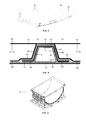
FIG. 1 is a schematic view of the components of a fan cowl of an aircraft engine and of its manufacturing method according to the invention.
FIG. 2 is a perspective view of an embodiment of a longitudinal beam of a fan cowl according to the invention.
FIG. 3a is an enlarged perspective view of the crossing zone of a longitudinal beam with a transverse frame showing a first part and two end portions of a second part of it.
FIG. 3b is an enlarged perspective view of the central portion of a second part of a longitudinal beam.
FIG. 4 is a perspective view of a zone the fan cowl in one of its borders.
FIG. 5 is a schematic cross-section view of the assembly of the fan-cowl components before the curing step.
FIG. 6 is a perspective view of the tooling used for curing the fan-cowl assembly.
DETAILED DESCRIPTION OF THE INVENTION
The structural components of the curvilinear fan cowl 11 of an aircraft engine according to the embodiment shown in the FIGS. 1-4 are a skin 13, transverse frames 15 with an omega-shaped cross-section and longitudinal beams 17, 19 (parallel to the longitudinal axis of the aircraft) with an I shaped cross-section except for the parts to be superimposed to the transverse frames 15. In this embodiment the configuration of the caps of the longitudinal beams 17, 19 in their crossing zones with the transverse frames 15 is adapted for being used as union areas of fittings of the engine.
In the embodiment illustrated in FIG. 1 the transverse frames 15 are equally spaced in the longitudinal direction of the fan cowl 11, two longitudinal beams 17 are placed over the transverse frames 15 in the upper and lower ends of the fan cowl 11 and three longitudinal beams 19 are placed over two transverse frames 15 in inner zones of the fan cowl 11.
As shown in FIG. 2, the longitudinal beams 17, 19 comprise first parts 21 in their crossing zones with the transverse frames 15 and second parts 23 in the rest of their length, having their webs arranged in a same plane.
The longitudinal beams 17 comprise four first parts 21 and three second parts 23 while the longitudinal beams 19 comprise two first parts 21 and one second part 23 (see FIG. 1).
As shown in FIGS. 3a and 3b , the first parts 21 of the longitudinal beams 17, 19 comprise a cap 31, two webs 30, 30′ and two feet 34, 34′ having a cross-section of an omega shape to be superimposed to the transverse frames 15 and the second parts 23 comprise a central portion 25 and two end portions 27 with webs 41.
The caps 31 of the first parts 21 are not symmetric with respect to the plane 40 of the webs 41 of the second parts 23. They have a first area of width W1 at one side of the plane 40 of the webs 41 and a second area of width W2 at the other side, being W2>W1.
The central portion 25 of the second parts 23 is symmetric with respect to its web 41. It has a cap 42 and a foot 44 of a constant width W3. As shown in FIG. 2 a longitudinal beam 17 can have a second part 23 with a central portion of a variable height to attend specific requirements. As shown in FIG. 3b , a central portion 25 can include ribs 50 as reinforcing elements in particularly loaded zones such as zones with fittings transmitting loads from external elements.
In the embodiment shown in the Figures the border of the first area of the caps 31 of the first parts 21 is aligned with the corresponding border of the cap 42 of the central portion 25 of the second parts 23 and therefore W3=2×W1.
The end portions 27 of the second parts 23 are not symmetric with respect to the plane 40 of their webs 41.
The caps 37 of the end portions 27 have a variable width for accommodating the change in width between the caps 42 of the central portions 25 of the second parts 23 and the caps 31 of the first parts 21.
As illustrated in FIG. 3a the widening of the caps 37 are concentrated towards the second area of the first parts 21. On the other side, the caps 37 include a recess 38.
The method of manufacturing the curvilinear fan cowl 11 of aircraft engines according to the present invention involves manufacturing separately the skin 13, the transverse frames 15, the longitudinal beams 17, 19 and the assembly of said components in the sequence illustrated in FIG. 1.
The transverse frames 15 and the longitudinal beams 17, 19 are provided to the assembly stage in a cured state and the skin 13 in an uncured state.
The skin 13 can be manufactured by a manufacturing method comprising the following steps:
-
- Automate fiber-placement of carbon fiber prepreg on a cylindrical mandrel.
- Lay-up of additional layers for lightning protection and/or erosion and/or impact protection.
- Unloading the skin 13 from the mandrel (the skins for the left and right fan-cowls can be made at the same time and then separated by a cutting method before unloading from the mandrel) for being located in the tool 61 used in the assembly stage of the fan cowl 11.
The transverse frames 15 and the longitudinal beams 17, 19 can be manufactured by any suitable CFRP (“Carbon Fiber Reinforced Plastic”) manufacturing method and, particularly, by a Resin Transfer Moulding (RTM) method for achieving a good dimensional control.
In reference to FIGS. 5 and 6 we will now describe the main steps of the manufacturing method according to the invention.
-
- The skin 13 with a metallic mesh 57 in its outer face is located on the autoclave tool 61.
- An adhesive layer 51 is laid-up on the inner faces of the transverse frames 15 in contact with the skin 13.
- The transverse frames 15, comprising a cap 12, two webs 16, 16′ and two feet 20, 20′, with an internal vacuum bag 49, are located over the skin 13 using a special bridge tooling (not shown) for controlling their position.
- A shim layer 55 with an adhesive ply over it is laid-up over the transverse frames 15 in the overlapping regions with the longitudinal frames to cover possible gaps between them due to tolerances.
- An adhesive layer 53 is laid-up on the inner face of the longitudinal beams 17, 19 in contact with the transversal frames 15 and the skin 13.
- The longitudinal beams 17, 19 are located over the transverse frames 15.
- A vacuum bag (not shown) is disposed over the assembly.
- An autoclave curing cycle at predetermined conditions of pressure and temperature is performed. In this step the skin 13 is co-bonded with the transverse frames 15 and the longitudinal beams 17, 19. The transverse frames 15 and the longitudinal beams 17, 19 are subject to a secondary bonding.
The assembly stage may also comprise laying-up local patches of glass fiber prepreg at specific locations of the skin 13, the transverse frames 15 and the longitudinal beams 17, 19 where aluminum fittings are going to be installed.
Although the present invention has been described in connection with various embodiments, it will be appreciated from the specification that various combinations of elements, variations or improvements therein may be made, and are within the scope of the invention.