EP2774854A1 - An improved monolithic fan cowl of an aircraft engine and a manufacturing method thereof - Google Patents
An improved monolithic fan cowl of an aircraft engine and a manufacturing method thereof Download PDFInfo
- Publication number
- EP2774854A1 EP2774854A1 EP13382070.4A EP13382070A EP2774854A1 EP 2774854 A1 EP2774854 A1 EP 2774854A1 EP 13382070 A EP13382070 A EP 13382070A EP 2774854 A1 EP2774854 A1 EP 2774854A1
- Authority
- EP
- European Patent Office
- Prior art keywords
- fan cowl
- transverse frames
- longitudinal beams
- skin
- transverse
- Prior art date
- Legal status (The legal status is an assumption and is not a legal conclusion. Google has not performed a legal analysis and makes no representation as to the accuracy of the status listed.)
- Granted
Links
- 238000004519 manufacturing process Methods 0.000 title claims abstract description 14
- 239000002131 composite material Substances 0.000 claims abstract description 9
- 239000010410 layer Substances 0.000 claims description 5
- 238000000034 method Methods 0.000 claims description 5
- 239000012790 adhesive layer Substances 0.000 claims description 4
- 238000005260 corrosion Methods 0.000 claims 1
- 230000007797 corrosion Effects 0.000 claims 1
- 238000009434 installation Methods 0.000 claims 1
- 239000004918 carbon fiber reinforced polymer Substances 0.000 description 2
- 229920000049 Carbon (fiber) Polymers 0.000 description 1
- 239000000853 adhesive Substances 0.000 description 1
- 230000001070 adhesive effect Effects 0.000 description 1
- XAGFODPZIPBFFR-UHFFFAOYSA-N aluminium Chemical compound [Al] XAGFODPZIPBFFR-UHFFFAOYSA-N 0.000 description 1
- 229910052782 aluminium Inorganic materials 0.000 description 1
- 239000004917 carbon fiber Substances 0.000 description 1
- 230000003628 erosive effect Effects 0.000 description 1
- 239000003365 glass fiber Substances 0.000 description 1
- 238000012423 maintenance Methods 0.000 description 1
- VNWKTOKETHGBQD-UHFFFAOYSA-N methane Chemical compound C VNWKTOKETHGBQD-UHFFFAOYSA-N 0.000 description 1
- 230000003014 reinforcing effect Effects 0.000 description 1
- 238000009745 resin transfer moulding Methods 0.000 description 1
Images


Classifications
-
- F—MECHANICAL ENGINEERING; LIGHTING; HEATING; WEAPONS; BLASTING
- F01—MACHINES OR ENGINES IN GENERAL; ENGINE PLANTS IN GENERAL; STEAM ENGINES
- F01D—NON-POSITIVE DISPLACEMENT MACHINES OR ENGINES, e.g. STEAM TURBINES
- F01D9/00—Stators
- F01D9/02—Nozzles; Nozzle boxes; Stator blades; Guide conduits, e.g. individual nozzles
-
- B—PERFORMING OPERATIONS; TRANSPORTING
- B29—WORKING OF PLASTICS; WORKING OF SUBSTANCES IN A PLASTIC STATE IN GENERAL
- B29C—SHAPING OR JOINING OF PLASTICS; SHAPING OF MATERIAL IN A PLASTIC STATE, NOT OTHERWISE PROVIDED FOR; AFTER-TREATMENT OF THE SHAPED PRODUCTS, e.g. REPAIRING
- B29C70/00—Shaping composites, i.e. plastics material comprising reinforcements, fillers or preformed parts, e.g. inserts
- B29C70/04—Shaping composites, i.e. plastics material comprising reinforcements, fillers or preformed parts, e.g. inserts comprising reinforcements only, e.g. self-reinforcing plastics
- B29C70/28—Shaping operations therefor
- B29C70/40—Shaping or impregnating by compression not applied
- B29C70/42—Shaping or impregnating by compression not applied for producing articles of definite length, i.e. discrete articles
- B29C70/44—Shaping or impregnating by compression not applied for producing articles of definite length, i.e. discrete articles using isostatic pressure, e.g. pressure difference-moulding, vacuum bag-moulding, autoclave-moulding or expanding rubber-moulding
-
- B—PERFORMING OPERATIONS; TRANSPORTING
- B29—WORKING OF PLASTICS; WORKING OF SUBSTANCES IN A PLASTIC STATE IN GENERAL
- B29D—PRODUCING PARTICULAR ARTICLES FROM PLASTICS OR FROM SUBSTANCES IN A PLASTIC STATE
- B29D99/00—Subject matter not provided for in other groups of this subclass
- B29D99/001—Producing wall or panel-like structures, e.g. for hulls, fuselages, or buildings
- B29D99/0014—Producing wall or panel-like structures, e.g. for hulls, fuselages, or buildings provided with ridges or ribs, e.g. joined ribs
-
- B—PERFORMING OPERATIONS; TRANSPORTING
- B64—AIRCRAFT; AVIATION; COSMONAUTICS
- B64D—EQUIPMENT FOR FITTING IN OR TO AIRCRAFT; FLIGHT SUITS; PARACHUTES; ARRANGEMENT OR MOUNTING OF POWER PLANTS OR PROPULSION TRANSMISSIONS IN AIRCRAFT
- B64D29/00—Power-plant nacelles, fairings, or cowlings
Definitions
- the nacelle of turbofan aircraft engines comprises right and left fan cowls covering internal parts of the engine that shall be operable to provide access to internal components of the engine for maintenance purposes.
Landscapes
- Engineering & Computer Science (AREA)
- Mechanical Engineering (AREA)
- Chemical & Material Sciences (AREA)
- Composite Materials (AREA)
- Aviation & Aerospace Engineering (AREA)
- Architecture (AREA)
- Civil Engineering (AREA)
- Structural Engineering (AREA)
- General Engineering & Computer Science (AREA)
- Moulding By Coating Moulds (AREA)
Abstract
Description
- The invention relates to a fan cowl of an aircraft engine and more in particular to a monolithic fan cowl made of composite material and to a manufacturing method of it.
- The nacelle of turbofan aircraft engines comprises right and left fan cowls covering internal parts of the engine that shall be operable to provide access to internal components of the engine for maintenance purposes.
-
WO 99/26841 -
EP 1 707 344 describes a method of manufacturing a monolithic fan cowl of composite materials with transverse and longitudinal beams of an omega-shaped cross-section. - A drawback of the fan cowls described in said documents is that the geometry of the longitudinal beams is not well adapted to the functional needs of the fan cowls with respect to the entry of loads.
- A drawback of the manufacturing methods described in said documents is that they use, basically, uncured composite materials implying tolerances in the final surfaces of the fan cowl.
- It is an object of the present invention to provide a fan cowl of an aircraft engine made of a composite material having an optimized structure for withstanding the expected loads and for being able to be manufactured as a monolithic ensemble with the desired final geometry and in a shorter time than in the prior art.
- In a first aspect, this and another objects are met by a monolithic curvilinear fan cowl of a composite material structured by a skin, frames of a closed cross-section (preferably of an omega cross-section) arranged in a transverse direction to the longitudinal axis of the aircraft and longitudinal beams comprising first parts of a closed cross-section to be superimposed to the transverse frames in their crossing zones and second parts of an open cross-section (preferably an I cross-section) in zones not crossing transverse frames having their webs arranged in a same plane. This structure allows achieving a fan cowl of a composite material with the required strength and a fan cowl that can be manufactured with the required geometry.
- In an embodiment the caps of the longitudinal beams have not a constant width along its length. In those portions suitable for being used as union areas of fittings of the engine, the caps have a variable width, larger in all its length than the width of portions of constant width.
- In an embodiment, the caps of the first parts of the longitudinal beams are asymmetric with respect to the plane of the webs of the second parts. The second parts comprise a central portion having a cap and a foot of constant width (and optionally transverse ribs in zones affected by concentrated loads) and end portions, having a cap and a foot of variable width, ending in the first parts. The second parts have generally a constant height (the same height as the first parts) but a longitudinal beam can include a second part with a central portion of a variable height in a particular zone of the fan cowl. This configuration is well adapted to the needs of the longitudinal beams of fan cowls that are preferably located in the upper and lower ends of the fan cowl and in its central zone.
- In a second aspect, the above-mentioned objects are met by a method of manufacturing said curvilinear fan cowl comprising the following steps: a) providing the skin uncured, the transverse frames cured and the longitudinal beams cured; the transverse frames and the longitudinal beams including respectively adhesive layers in their inner faces in contact with other components; b) placing the skin on an autoclave tool; c) placing said transverse frames with a vacuum bag inserted into them on the skin; d) placing said longitudinal beams over the transverse frames and the skin; e) covering the assembly with a vacuum bag; f) performing an autoclave cycle under predetermined temperature and pressure conditions for co-bonding the skin, the transverse frames and the longitudinal beams and for carrying out a secondary bonding of the longitudinal beams to the transverse frames.
- The use of transversal frames and longitudinal beams cured allows a better control of the geometry of the fan cowl and reduces the manufacturing time.
- Other desirable features and advantages of the invention will become apparent from the subsequent detailed description of the invention and the appended claims, in relation with the enclosed drawings.
-
-
Figure 1 is a schematic view of the components of a fan cowl of an aircraft engine and of its manufacturing method according to the invention. -
Figure 2 is a perspective view of an embodiment of a longitudinal beam of a fan cowl according to the invention. -
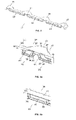
Figure 3a is an enlarged perspective view of the crossing zone of a longitudinal beam with a transverse frame showing a first part and two end portions of a second part of it. -
Figure 3b is an enlarged perspective view of the central portion of a second part of a longitudinal beam. -
Figure 4 is a perspective view of a zone the fan cowl in one of its borders. -
Figure 5 is a schematic cross-section view of the assembly of the fan-cowl components before the curing step. -
Figure 6 is a perspective view of the tooling used for curing the fan-cowl assembly. - The structural components of the
curvilinear fan cowl 11 of an aircraft engine according to the embodiment shown in theFigures 1-4 are askin 13,transverse frames 15 with an omega-shaped cross-section andlongitudinal beams 17, 19 (parallel to the longitudinal axis of the aircraft) with an I shaped cross-section except for the parts to be superimposed to thetransverse frames 15. In this embodiment the configuration of the caps of thelongitudinal beams transverse frames 15 is adapted for being used as union areas of fittings of the engine. - In the embodiment illustrated in
Figure 1 thetransverse frames 15 are equally spaced in the longitudinal direction of thefan cowl 11, twolongitudinal beams 17 are placed over thetransverse frames 15 in the upper and lower ends of thefan cowl 11 and threelongitudinal beams 19 are placed over twotransverse frames 15 in inner zones of thefan cowl 11. - As shown in
Figure 2 , thelongitudinal beams first parts 21 in their crossing zones with thetransverse frames 15 andsecond parts 23 in the rest of their length, having their webs arranged in a same plane. - The
longitudinal beams 17 comprise fourfirst parts 21 and threesecond parts 23 while thelongitudinal beams 19 comprise twofirst parts 21 and one second part 23 (seeFig 1 ). - As shown in
Figures 3a and 3b , thefirst parts 21 of thelongitudinal beams cap 31, twowebs 30, 30' and twofeet 34, 34' having a cross-section of an omega shape to be superimposed to thetransverse frames 15 and thesecond parts 23 comprise acentral portion 25 and twoend portions 27 withwebs 41. - The
caps 31 of thefirst parts 21 are not symmetric with respect to theplane 40 of thewebs 41 of thesecond parts 23. They have a first area of width W1 at one side of theplane 40 of thewebs 41 and a second area of width W2 at the other side, being W2>W1. - The
central portion 25 of thesecond parts 23 is symmetric with respect to itsweb 41. It has acap 42 and afoot 44 of a constant width W3. As shown inFigure 2 alongitudinal beam 17 can have asecond part 23 with a central portion of a variable height to attend specific requirements. As shown inFigure 3b , acentral portion 25 can includeribs 50 as reinforcing elements in particularly loaded zones such as zones with fittings transmitting loads from external elements. - In the embodiment shown in the Figures the border of the first area of the
caps 31 of thefirst parts 21 is aligned with the corresponding border of thecap 42 of thecentral portion 25 of thesecond parts 23 and therefore W3= 2 x W1. - The
end portions 27 of thesecond parts 23 are not symmetric with respect to theplane 40 of theirwebs 41. - The
caps 37 of theend portions 27 have a variable width for accommodating the change in width between thecaps 42 of thecentral portions 25 of thesecond parts 23 and thecaps 31 of thefirst parts 21. - As illustrated in
Figure 3a the widening of thecaps 37 are concentrated towards the second area of thefirst parts 21. On the other side, thecaps 37 include arecess 38. - The method of manufacturing the
curvilinear fan cowl 11 of aircraft engines according to the present invention involves manufacturing separately theskin 13, thetransverse frames 15, thelongitudinal beams Figure 1 . - The
transverse frames 15 and thelongitudinal beams skin 13 in an uncured state. - The
skin 13 can be manufactured by a manufacturing method comprising the following steps: - Automate fiber-placement of carbon fiber prepreg on a cylindrical mandrel.
- Lay-up of additional layers for lightning protection and/or erosion and/or impact protection.
- Unloading the
skin 13 from the mandrel (the skins for the left and right fan-cowls can be made at the same time and then separated by a cutting method before unloading from the mandrel) for being located in thetool 61 used in the assembly stage of thefan cowl 11. - The
transverse frames 15 and thelongitudinal beams - In reference to
Figures 5 and 6 we will now describe the main steps of the manufacturing method according to the invention. - The
skin 13 with ametallic mesh 57 in its outer face is located on theautoclave tool 61. - An
adhesive layer 51 is laid-up on the inner faces of thetransverse frames 15 in contact with theskin 13. - The
transverse frames 15, comprising acap 12, twowebs 16, 16' and twofeet 20, 20', with aninternal vacuum bag 49, are located over theskin 13 using a special bridge tooling (not shown) for controlling their position. - A
shim layer 55 with an adhesive ply over it is laid-up over thetransverse frames 15 in the overlapping regions with the longitudinal frames to cover possible gaps between them due to tolerances. - An
adhesive layer 53 is laid-up on the inner face of thelongitudinal beams transversal frames 15 and theskin 13. - The
longitudinal beams transverse frames 15. - A vacuum bag (not shown) is disposed over the assembly.
- An autoclave curing cycle at predetermined conditions of pressure and temperature is performed. In this step the
skin 13 is co-bonded with thetransverse frames 15 and thelongitudinal beams transverse frames 15 and thelongitudinal beams - The assembly stage may also comprise laying-up local patches of glass fiber prepreg at specific locations of the
skin 13, thetransverse frames 15 and thelongitudinal beams - Although the present invention has been described in connection with various embodiments, it will be appreciated from the specification that various combinations of elements, variations or improvements therein may be made, and are within the scope of the invention.
Claims (12)
- A curvilinear fan cowl (11) of an aircraft engine made of a composite material having a longitudinal axis parallel to the longitudinal axis of the aircraft; the fan cowl (11) comprising a skin (13), transverse frames (15) and longitudinal beams (17, 19); the transverse frames (15) being configured with a closed cross-section comprising a cap (12), two webs (16, 16') and two feet (20, 20'); the longitudinal beams (17, 19) being formed by at least a first part (21) in a zone crossing a transverse frame (15) and at least a second part (23) in a zone not crossing a transverse frame (15); each first part (21) being configured with a closed cross-section comprising a cap (31), two webs (30, 30') and two feet (34, 34') and having the same shape as the transverse frames (15) so that it can be superimposed to a transverse frame (15) in their crossing zones; characterized in that:- each second part (23) of the longitudinal beams (17, 19) is configured with an open cross-section comprising a cap, a web (41) and a foot;- the webs (41) of the second parts (23) of the longitudinal beams (17, 19) are arranged in a same plane (40);- the curvilinear fan cowl (11) is a monolithic ensemble.
- A curvilinear fan cowl (11) according to claim 1, wherein the cap of at least one longitudinal beam (17, 19) comprise at least a first portion having a constant width W1 at both sides of the plane (40) of the webs (41) and at least a second portion, suitable for being used as an union area of fittings of the engine, having a width W larger than 2 x W1 along its length.
- A curvilinear fan cowl (11) according to claim 2, wherein:- the caps (31) of the first parts (21) of said longitudinal beam (17, 19) comprise a first area of width W1 at one side of the plane (40) of the webs (41) and a second area of width W2 at the other side, being W1 <W2;- the caps of the second parts (23) of said longitudinal beam (17, 19) comprise a central cap (42) of constant width W3, being W3= 2 x W1, and at least an end cap (37) having a recess (38) at one side of the plane (40) of the webs (41) and a variable width W, increasing from W1 to W2, at the other side.
- A curvilinear fan cowl (11) according to any of claims 1-3, wherein the second parts (23) include transverse ribs (50) to the webs (41).
- A curvilinear fan cowl (11) according to any of claims 1-4, wherein at least a longitudinal beam (17, 19) comprise a second part (23) with a central portion (25) of a variable height.
- A curvilinear fan cowl (11) according to any of claims 1-5, wherein the transverse frames (15) are configured with an omega-shaped cross-section.
- A curvilinear fan cowl (11) according to any of claims 1-6, comprising at least two longitudinal beams (17) superimposed to all the transverse frames (15) in their upper and lower ends.
- A curvilinear fan cowl (11) according to claim 7, further comprising at least one longitudinal beam (19) superimposed to a sub-group of the transverse frames (15) in inner zones of the fan cowl (11) affected by loads transmitted by fittings installed in said inner zones.
- Method of manufacturing a curvilinear fan cowl (11) according to any of claims 1-8 comprising the following steps:a) providing the skin (13) uncured, the transverse frames (15) cured and the longitudinal beams (17, 19) cured; the transverse frames (15) and the longitudinal beams (17, 19) including respectively adhesive layers (51, 53) in their inner faces in contact with other components;b) placing the skin (13) on an autoclave tool (61);c) placing said transverse frames (15) with internal vacuum bags (49) on the skin (13), the vacuum bags (49) being used during an autoclave cycle;d) placing said longitudinal beams (17, 19) over the transverse frames (15) and the skin (13);e) covering the assembly with a vacuum bag;f) performing an autoclave cycle under predetermined temperature and pressure conditions for co-bonding the skin (13), the transverse frames (15) and the longitudinal beams (17, 19) and for a secondary bonding of the longitudinal beams (17, 19) to the transverse frames (15).
- Method according to claim 9, wherein the step d) also comprises placing a shim layer (55) over the areas of transverse frames (15) to be crossed by the longitudinal beams (17, 19).
- Method according to any of claims 9-10, also comprising laying-up patches of a corrosion protection layer in those locations of the skin (13), the transverse frames (15) and the longitudinal beams (17, 19) foreseen for the installation of metallic fittings.
- Method according to any of claims 9-11, wherein in step a) the uncured skin (13) is provided with a lightening protecting layer (57) in its outer face.
Priority Applications (3)
| Application Number | Priority Date | Filing Date | Title |
|---|---|---|---|
| EP13382070.4A EP2774854B1 (en) | 2013-03-04 | 2013-03-04 | An improved monolithic fan cowl of an aircraft engine and a manufacturing method thereof |
| ES13382070.4T ES2635122T3 (en) | 2013-03-04 | 2013-03-04 | Improved monolithic hood of an aircraft engine and manufacturing method |
| US14/196,330 US9677409B2 (en) | 2013-03-04 | 2014-03-04 | Monolithic fan cowl of an aircraft engine and a manufacturing method thereof |
Applications Claiming Priority (1)
| Application Number | Priority Date | Filing Date | Title |
|---|---|---|---|
| EP13382070.4A EP2774854B1 (en) | 2013-03-04 | 2013-03-04 | An improved monolithic fan cowl of an aircraft engine and a manufacturing method thereof |
Publications (2)
| Publication Number | Publication Date |
|---|---|
| EP2774854A1 true EP2774854A1 (en) | 2014-09-10 |
| EP2774854B1 EP2774854B1 (en) | 2017-05-03 |
Family
ID=47913351
Family Applications (1)
| Application Number | Title | Priority Date | Filing Date |
|---|---|---|---|
| EP13382070.4A Active EP2774854B1 (en) | 2013-03-04 | 2013-03-04 | An improved monolithic fan cowl of an aircraft engine and a manufacturing method thereof |
Country Status (3)
| Country | Link |
|---|---|
| US (1) | US9677409B2 (en) |
| EP (1) | EP2774854B1 (en) |
| ES (1) | ES2635122T3 (en) |
Cited By (3)
| Publication number | Priority date | Publication date | Assignee | Title |
|---|---|---|---|---|
| IT202000032414A1 (en) * | 2020-12-24 | 2022-06-24 | Aeronautical Service S R L | AIRCRAFT DOOR AND PRODUCTION METHOD. |
| FR3121660A1 (en) * | 2021-04-12 | 2022-10-14 | Safran Nacelles | Curved stiffener for a turbomachine nacelle and method of manufacturing such a stiffener |
| DE102022206242A1 (en) | 2022-06-22 | 2023-12-28 | Rolls-Royce Deutschland Ltd & Co Kg | Method for producing an engine component from at least one fiber-reinforced plastic |
Families Citing this family (3)
| Publication number | Priority date | Publication date | Assignee | Title |
|---|---|---|---|---|
| US11059206B2 (en) * | 2016-02-05 | 2021-07-13 | Rohr, Inc | Method for fabricating composite structures using combined resin film and dry fabric |
| US10479517B2 (en) * | 2016-12-05 | 2019-11-19 | The Boeing Company | Composite fan cowl with a core having tailored thickness |
| CN114060305B (en) * | 2020-07-29 | 2024-07-12 | 中国航发商用航空发动机有限责任公司 | Fan containing casing and preparation method thereof |
Citations (6)
| Publication number | Priority date | Publication date | Assignee | Title |
|---|---|---|---|---|
| US4471609A (en) * | 1982-08-23 | 1984-09-18 | The Boeing Company | Apparatus and method for minimizing engine backbone bending |
| FR2771331A1 (en) * | 1997-11-21 | 1999-05-28 | Aerospatiale | Aircraft panel |
| WO1999026841A1 (en) | 1997-11-26 | 1999-06-03 | Aerospatiale Societe Nationale Industrielle | Method for making a composite panel and resulting panel |
| EP1707344A1 (en) | 2005-03-30 | 2006-10-04 | Eads Construcciones Aeronauticas S.A. | Process for manufacturing a monolithic fan cowl |
| US20120001023A1 (en) * | 2010-06-30 | 2012-01-05 | Airbus Operations, S.L. | Aircraft fuselage made out with composite material and manufacturing processes |
| DE102011012319A1 (en) * | 2011-02-25 | 2012-08-30 | Daimler Ag | Method for joining a component made of a fiber-reinforced composite material with a component made of a metal and connecting arrangement of such components |
Family Cites Families (3)
| Publication number | Priority date | Publication date | Assignee | Title |
|---|---|---|---|---|
| US5297765A (en) * | 1992-11-02 | 1994-03-29 | Rohr, Inc. | Turbine engine nacelle laminar flow control arrangement |
| US6458309B1 (en) * | 1998-06-01 | 2002-10-01 | Rohr, Inc. | Method for fabricating an advanced composite aerostructure article having an integral co-cured fly away hollow mandrel |
| US6358014B1 (en) * | 2000-03-24 | 2002-03-19 | General Electric Company | Composite spinner and method of making the same |
-
2013
- 2013-03-04 ES ES13382070.4T patent/ES2635122T3/en active Active
- 2013-03-04 EP EP13382070.4A patent/EP2774854B1/en active Active
-
2014
- 2014-03-04 US US14/196,330 patent/US9677409B2/en active Active
Patent Citations (6)
| Publication number | Priority date | Publication date | Assignee | Title |
|---|---|---|---|---|
| US4471609A (en) * | 1982-08-23 | 1984-09-18 | The Boeing Company | Apparatus and method for minimizing engine backbone bending |
| FR2771331A1 (en) * | 1997-11-21 | 1999-05-28 | Aerospatiale | Aircraft panel |
| WO1999026841A1 (en) | 1997-11-26 | 1999-06-03 | Aerospatiale Societe Nationale Industrielle | Method for making a composite panel and resulting panel |
| EP1707344A1 (en) | 2005-03-30 | 2006-10-04 | Eads Construcciones Aeronauticas S.A. | Process for manufacturing a monolithic fan cowl |
| US20120001023A1 (en) * | 2010-06-30 | 2012-01-05 | Airbus Operations, S.L. | Aircraft fuselage made out with composite material and manufacturing processes |
| DE102011012319A1 (en) * | 2011-02-25 | 2012-08-30 | Daimler Ag | Method for joining a component made of a fiber-reinforced composite material with a component made of a metal and connecting arrangement of such components |
Cited By (5)
| Publication number | Priority date | Publication date | Assignee | Title |
|---|---|---|---|---|
| IT202000032414A1 (en) * | 2020-12-24 | 2022-06-24 | Aeronautical Service S R L | AIRCRAFT DOOR AND PRODUCTION METHOD. |
| WO2022137267A1 (en) * | 2020-12-24 | 2022-06-30 | Aeronautical Service S.R.L. | Aircraft door and production method |
| FR3121660A1 (en) * | 2021-04-12 | 2022-10-14 | Safran Nacelles | Curved stiffener for a turbomachine nacelle and method of manufacturing such a stiffener |
| WO2022219271A1 (en) * | 2021-04-12 | 2022-10-20 | Safran Nacelles | Curved stiffener for a turbine engine nacelle and method for producing such a stiffener |
| DE102022206242A1 (en) | 2022-06-22 | 2023-12-28 | Rolls-Royce Deutschland Ltd & Co Kg | Method for producing an engine component from at least one fiber-reinforced plastic |
Also Published As
| Publication number | Publication date |
|---|---|
| EP2774854B1 (en) | 2017-05-03 |
| US9677409B2 (en) | 2017-06-13 |
| US20140248143A1 (en) | 2014-09-04 |
| ES2635122T3 (en) | 2017-10-02 |
Similar Documents
| Publication | Publication Date | Title |
|---|---|---|
| EP2301840B1 (en) | Integrated aircraft structure in composite material | |
| JP5801885B2 (en) | Composite structure having integral stiffener and method for producing the same | |
| EP2774854B1 (en) | An improved monolithic fan cowl of an aircraft engine and a manufacturing method thereof | |
| KR101846592B1 (en) | Method and system of making composite structures having gap fillers with chopped fiber material | |
| CA2714175C (en) | Method for manufacturing a fibre-composite component, fibre-composite component and fibre-composite fuselage component of an aircraft | |
| US9669581B2 (en) | Method for manufacturing an aeronautical torsion box, torsion box and tool for manufacturing an aeronautical torsion box | |
| US9359060B2 (en) | Laminated composite radius filler with geometric shaped filler element and method of forming the same | |
| EP1800842B1 (en) | A method of manufacturing an elongate structural element configured for stiffening a shell structure, and a method for manufacturing a rigid shell structure integrated with at least one elongate stiffening element | |
| US20130020438A1 (en) | Flexible Truss Frame and Method of Making the Same | |
| EP2865516B1 (en) | Skin-stiffened composite panel and method of its manufacture | |
| EP2439059B1 (en) | Method and device for forming joints in composite structures | |
| EP3483057B1 (en) | Reinforcing arrangement for an opening in an aircraft structure | |
| US11220354B2 (en) | Composite fuselage assembly and methods to form the assembly | |
| EP2977192B1 (en) | Fabric jacketed unidirectional noodle and its method of construction | |
| EP1899149B1 (en) | Process for producing a substantially shell-shaped component | |
| US20110206875A1 (en) | Method and arrangement for production of an integral hollow-profiled component with fibre composite material | |
| US20170225406A1 (en) | Method for manufacturing a stiffened panel made from composite material | |
| US20110311782A1 (en) | Planar component of an aircraft and method for producing the same | |
| US20150064393A1 (en) | Laminate for joining parts, and method and system for joining parts | |
| US8870117B2 (en) | Composite aircraft frame | |
| US11267584B2 (en) | Method for manufacturing a rear section of an aircraft and aircraft rear section | |
| WO2013014283A1 (en) | A device for the manufacture of a bonded component with fibre-reinforced plastics and also a method |
Legal Events
| Date | Code | Title | Description |
|---|---|---|---|
| PUAI | Public reference made under article 153(3) epc to a published international application that has entered the european phase |
Free format text: ORIGINAL CODE: 0009012 |
|
| 17P | Request for examination filed |
Effective date: 20130304 |
|
| AK | Designated contracting states |
Kind code of ref document: A1 Designated state(s): AL AT BE BG CH CY CZ DE DK EE ES FI FR GB GR HR HU IE IS IT LI LT LU LV MC MK MT NL NO PL PT RO RS SE SI SK SM TR |
|
| AX | Request for extension of the european patent |
Extension state: BA ME |
|
| R17P | Request for examination filed (corrected) |
Effective date: 20150310 |
|
| RBV | Designated contracting states (corrected) |
Designated state(s): AL AT BE BG CH CY CZ DE DK EE ES FI FR GB GR HR HU IE IS IT LI LT LU LV MC MK MT NL NO PL PT RO RS SE SI SK SM TR |
|
| RAP1 | Party data changed (applicant data changed or rights of an application transferred) |
Owner name: AIRBUS DEFENCE AND SPACE SA |
|
| GRAP | Despatch of communication of intention to grant a patent |
Free format text: ORIGINAL CODE: EPIDOSNIGR1 |
|
| INTG | Intention to grant announced |
Effective date: 20161125 |
|
| GRAS | Grant fee paid |
Free format text: ORIGINAL CODE: EPIDOSNIGR3 |
|
| GRAA | (expected) grant |
Free format text: ORIGINAL CODE: 0009210 |
|
| AK | Designated contracting states |
Kind code of ref document: B1 Designated state(s): AL AT BE BG CH CY CZ DE DK EE ES FI FR GB GR HR HU IE IS IT LI LT LU LV MC MK MT NL NO PL PT RO RS SE SI SK SM TR |
|
| REG | Reference to a national code |
Ref country code: GB Ref legal event code: FG4D |
|
| REG | Reference to a national code |
Ref country code: AT Ref legal event code: REF Ref document number: 889666 Country of ref document: AT Kind code of ref document: T Effective date: 20170515 Ref country code: CH Ref legal event code: EP |
|
| REG | Reference to a national code |
Ref country code: IE Ref legal event code: FG4D |
|
| REG | Reference to a national code |
Ref country code: DE Ref legal event code: R096 Ref document number: 602013020547 Country of ref document: DE |
|
| REG | Reference to a national code |
Ref country code: NL Ref legal event code: MP Effective date: 20170503 |
|
| REG | Reference to a national code |
Ref country code: AT Ref legal event code: MK05 Ref document number: 889666 Country of ref document: AT Kind code of ref document: T Effective date: 20170503 |
|
| REG | Reference to a national code |
Ref country code: LT Ref legal event code: MG4D |
|
| REG | Reference to a national code |
Ref country code: ES Ref legal event code: FG2A Ref document number: 2635122 Country of ref document: ES Kind code of ref document: T3 Effective date: 20171002 |
|
| PG25 | Lapsed in a contracting state [announced via postgrant information from national office to epo] |
Ref country code: GR Free format text: LAPSE BECAUSE OF FAILURE TO SUBMIT A TRANSLATION OF THE DESCRIPTION OR TO PAY THE FEE WITHIN THE PRESCRIBED TIME-LIMIT Effective date: 20170804 Ref country code: LT Free format text: LAPSE BECAUSE OF FAILURE TO SUBMIT A TRANSLATION OF THE DESCRIPTION OR TO PAY THE FEE WITHIN THE PRESCRIBED TIME-LIMIT Effective date: 20170503 Ref country code: FI Free format text: LAPSE BECAUSE OF FAILURE TO SUBMIT A TRANSLATION OF THE DESCRIPTION OR TO PAY THE FEE WITHIN THE PRESCRIBED TIME-LIMIT Effective date: 20170503 Ref country code: AT Free format text: LAPSE BECAUSE OF FAILURE TO SUBMIT A TRANSLATION OF THE DESCRIPTION OR TO PAY THE FEE WITHIN THE PRESCRIBED TIME-LIMIT Effective date: 20170503 Ref country code: NO Free format text: LAPSE BECAUSE OF FAILURE TO SUBMIT A TRANSLATION OF THE DESCRIPTION OR TO PAY THE FEE WITHIN THE PRESCRIBED TIME-LIMIT Effective date: 20170803 Ref country code: HR Free format text: LAPSE BECAUSE OF FAILURE TO SUBMIT A TRANSLATION OF THE DESCRIPTION OR TO PAY THE FEE WITHIN THE PRESCRIBED TIME-LIMIT Effective date: 20170503 |
|
| PG25 | Lapsed in a contracting state [announced via postgrant information from national office to epo] |
Ref country code: NL Free format text: LAPSE BECAUSE OF FAILURE TO SUBMIT A TRANSLATION OF THE DESCRIPTION OR TO PAY THE FEE WITHIN THE PRESCRIBED TIME-LIMIT Effective date: 20170503 Ref country code: LV Free format text: LAPSE BECAUSE OF FAILURE TO SUBMIT A TRANSLATION OF THE DESCRIPTION OR TO PAY THE FEE WITHIN THE PRESCRIBED TIME-LIMIT Effective date: 20170503 Ref country code: RS Free format text: LAPSE BECAUSE OF FAILURE TO SUBMIT A TRANSLATION OF THE DESCRIPTION OR TO PAY THE FEE WITHIN THE PRESCRIBED TIME-LIMIT Effective date: 20170503 Ref country code: IS Free format text: LAPSE BECAUSE OF FAILURE TO SUBMIT A TRANSLATION OF THE DESCRIPTION OR TO PAY THE FEE WITHIN THE PRESCRIBED TIME-LIMIT Effective date: 20170903 Ref country code: BG Free format text: LAPSE BECAUSE OF FAILURE TO SUBMIT A TRANSLATION OF THE DESCRIPTION OR TO PAY THE FEE WITHIN THE PRESCRIBED TIME-LIMIT Effective date: 20170803 Ref country code: SE Free format text: LAPSE BECAUSE OF FAILURE TO SUBMIT A TRANSLATION OF THE DESCRIPTION OR TO PAY THE FEE WITHIN THE PRESCRIBED TIME-LIMIT Effective date: 20170503 Ref country code: PL Free format text: LAPSE BECAUSE OF FAILURE TO SUBMIT A TRANSLATION OF THE DESCRIPTION OR TO PAY THE FEE WITHIN THE PRESCRIBED TIME-LIMIT Effective date: 20170503 |
|
| PG25 | Lapsed in a contracting state [announced via postgrant information from national office to epo] |
Ref country code: SK Free format text: LAPSE BECAUSE OF FAILURE TO SUBMIT A TRANSLATION OF THE DESCRIPTION OR TO PAY THE FEE WITHIN THE PRESCRIBED TIME-LIMIT Effective date: 20170503 Ref country code: CZ Free format text: LAPSE BECAUSE OF FAILURE TO SUBMIT A TRANSLATION OF THE DESCRIPTION OR TO PAY THE FEE WITHIN THE PRESCRIBED TIME-LIMIT Effective date: 20170503 Ref country code: EE Free format text: LAPSE BECAUSE OF FAILURE TO SUBMIT A TRANSLATION OF THE DESCRIPTION OR TO PAY THE FEE WITHIN THE PRESCRIBED TIME-LIMIT Effective date: 20170503 Ref country code: RO Free format text: LAPSE BECAUSE OF FAILURE TO SUBMIT A TRANSLATION OF THE DESCRIPTION OR TO PAY THE FEE WITHIN THE PRESCRIBED TIME-LIMIT Effective date: 20170503 Ref country code: DK Free format text: LAPSE BECAUSE OF FAILURE TO SUBMIT A TRANSLATION OF THE DESCRIPTION OR TO PAY THE FEE WITHIN THE PRESCRIBED TIME-LIMIT Effective date: 20170503 |
|
| REG | Reference to a national code |
Ref country code: DE Ref legal event code: R097 Ref document number: 602013020547 Country of ref document: DE |
|
| PG25 | Lapsed in a contracting state [announced via postgrant information from national office to epo] |
Ref country code: SM Free format text: LAPSE BECAUSE OF FAILURE TO SUBMIT A TRANSLATION OF THE DESCRIPTION OR TO PAY THE FEE WITHIN THE PRESCRIBED TIME-LIMIT Effective date: 20170503 Ref country code: IT Free format text: LAPSE BECAUSE OF FAILURE TO SUBMIT A TRANSLATION OF THE DESCRIPTION OR TO PAY THE FEE WITHIN THE PRESCRIBED TIME-LIMIT Effective date: 20170503 |
|
| PLBE | No opposition filed within time limit |
Free format text: ORIGINAL CODE: 0009261 |
|
| STAA | Information on the status of an ep patent application or granted ep patent |
Free format text: STATUS: NO OPPOSITION FILED WITHIN TIME LIMIT |
|
| REG | Reference to a national code |
Ref country code: FR Ref legal event code: PLFP Year of fee payment: 6 |
|
| 26N | No opposition filed |
Effective date: 20180206 |
|
| PG25 | Lapsed in a contracting state [announced via postgrant information from national office to epo] |
Ref country code: SI Free format text: LAPSE BECAUSE OF FAILURE TO SUBMIT A TRANSLATION OF THE DESCRIPTION OR TO PAY THE FEE WITHIN THE PRESCRIBED TIME-LIMIT Effective date: 20170503 |
|
| REG | Reference to a national code |
Ref country code: CH Ref legal event code: PL |
|
| PG25 | Lapsed in a contracting state [announced via postgrant information from national office to epo] |
Ref country code: MC Free format text: LAPSE BECAUSE OF FAILURE TO SUBMIT A TRANSLATION OF THE DESCRIPTION OR TO PAY THE FEE WITHIN THE PRESCRIBED TIME-LIMIT Effective date: 20170503 |
|
| REG | Reference to a national code |
Ref country code: BE Ref legal event code: MM Effective date: 20180331 |
|
| REG | Reference to a national code |
Ref country code: IE Ref legal event code: MM4A |
|
| PG25 | Lapsed in a contracting state [announced via postgrant information from national office to epo] |
Ref country code: LU Free format text: LAPSE BECAUSE OF NON-PAYMENT OF DUE FEES Effective date: 20180304 |
|
| PG25 | Lapsed in a contracting state [announced via postgrant information from national office to epo] |
Ref country code: IE Free format text: LAPSE BECAUSE OF NON-PAYMENT OF DUE FEES Effective date: 20180304 |
|
| PG25 | Lapsed in a contracting state [announced via postgrant information from national office to epo] |
Ref country code: BE Free format text: LAPSE BECAUSE OF NON-PAYMENT OF DUE FEES Effective date: 20180331 Ref country code: CH Free format text: LAPSE BECAUSE OF NON-PAYMENT OF DUE FEES Effective date: 20180331 Ref country code: LI Free format text: LAPSE BECAUSE OF NON-PAYMENT OF DUE FEES Effective date: 20180331 |
|
| PG25 | Lapsed in a contracting state [announced via postgrant information from national office to epo] |
Ref country code: MT Free format text: LAPSE BECAUSE OF NON-PAYMENT OF DUE FEES Effective date: 20180304 |
|
| PG25 | Lapsed in a contracting state [announced via postgrant information from national office to epo] |
Ref country code: TR Free format text: LAPSE BECAUSE OF FAILURE TO SUBMIT A TRANSLATION OF THE DESCRIPTION OR TO PAY THE FEE WITHIN THE PRESCRIBED TIME-LIMIT Effective date: 20170503 |
|
| PG25 | Lapsed in a contracting state [announced via postgrant information from national office to epo] |
Ref country code: PT Free format text: LAPSE BECAUSE OF FAILURE TO SUBMIT A TRANSLATION OF THE DESCRIPTION OR TO PAY THE FEE WITHIN THE PRESCRIBED TIME-LIMIT Effective date: 20170503 Ref country code: HU Free format text: LAPSE BECAUSE OF FAILURE TO SUBMIT A TRANSLATION OF THE DESCRIPTION OR TO PAY THE FEE WITHIN THE PRESCRIBED TIME-LIMIT; INVALID AB INITIO Effective date: 20130304 |
|
| PG25 | Lapsed in a contracting state [announced via postgrant information from national office to epo] |
Ref country code: CY Free format text: LAPSE BECAUSE OF FAILURE TO SUBMIT A TRANSLATION OF THE DESCRIPTION OR TO PAY THE FEE WITHIN THE PRESCRIBED TIME-LIMIT Effective date: 20170503 Ref country code: MK Free format text: LAPSE BECAUSE OF NON-PAYMENT OF DUE FEES Effective date: 20170503 |
|
| PG25 | Lapsed in a contracting state [announced via postgrant information from national office to epo] |
Ref country code: AL Free format text: LAPSE BECAUSE OF FAILURE TO SUBMIT A TRANSLATION OF THE DESCRIPTION OR TO PAY THE FEE WITHIN THE PRESCRIBED TIME-LIMIT Effective date: 20170503 |
|
| PGFP | Annual fee paid to national office [announced via postgrant information from national office to epo] |
Ref country code: DE Payment date: 20240320 Year of fee payment: 12 Ref country code: GB Payment date: 20240320 Year of fee payment: 12 |
|
| PGFP | Annual fee paid to national office [announced via postgrant information from national office to epo] |
Ref country code: FR Payment date: 20240327 Year of fee payment: 12 |
|
| PGFP | Annual fee paid to national office [announced via postgrant information from national office to epo] |
Ref country code: ES Payment date: 20240426 Year of fee payment: 12 |