US9677409B2 - Monolithic fan cowl of an aircraft engine and a manufacturing method thereof - Google Patents
Monolithic fan cowl of an aircraft engine and a manufacturing method thereof Download PDFInfo
- Publication number
- US9677409B2 US9677409B2 US14/196,330 US201414196330A US9677409B2 US 9677409 B2 US9677409 B2 US 9677409B2 US 201414196330 A US201414196330 A US 201414196330A US 9677409 B2 US9677409 B2 US 9677409B2
- Authority
- US
- United States
- Prior art keywords
- cap
- skin
- transverse frames
- longitudinal beams
- fan cowl
- Prior art date
- Legal status (The legal status is an assumption and is not a legal conclusion. Google has not performed a legal analysis and makes no representation as to the accuracy of the status listed.)
- Active, expires
Links
- 238000004519 manufacturing process Methods 0.000 title claims abstract description 14
- 239000002131 composite material Substances 0.000 claims abstract description 13
- 239000010410 layer Substances 0.000 claims description 5
- 238000000034 method Methods 0.000 claims description 5
- 239000012790 adhesive layer Substances 0.000 claims description 4
- 238000005260 corrosion Methods 0.000 claims 1
- 230000007797 corrosion Effects 0.000 claims 1
- 238000009434 installation Methods 0.000 claims 1
- 239000004918 carbon fiber reinforced polymer Substances 0.000 description 2
- 229920000049 Carbon (fiber) Polymers 0.000 description 1
- 239000000853 adhesive Substances 0.000 description 1
- 230000001070 adhesive effect Effects 0.000 description 1
- XAGFODPZIPBFFR-UHFFFAOYSA-N aluminium Chemical compound [Al] XAGFODPZIPBFFR-UHFFFAOYSA-N 0.000 description 1
- 229910052782 aluminium Inorganic materials 0.000 description 1
- 239000004917 carbon fiber Substances 0.000 description 1
- 230000003628 erosive effect Effects 0.000 description 1
- 239000003365 glass fiber Substances 0.000 description 1
- 238000012423 maintenance Methods 0.000 description 1
- VNWKTOKETHGBQD-UHFFFAOYSA-N methane Chemical compound C VNWKTOKETHGBQD-UHFFFAOYSA-N 0.000 description 1
- 230000003014 reinforcing effect Effects 0.000 description 1
- 238000009745 resin transfer moulding Methods 0.000 description 1
Images


Classifications
-
- F—MECHANICAL ENGINEERING; LIGHTING; HEATING; WEAPONS; BLASTING
- F01—MACHINES OR ENGINES IN GENERAL; ENGINE PLANTS IN GENERAL; STEAM ENGINES
- F01D—NON-POSITIVE DISPLACEMENT MACHINES OR ENGINES, e.g. STEAM TURBINES
- F01D9/00—Stators
- F01D9/02—Nozzles; Nozzle boxes; Stator blades; Guide conduits, e.g. individual nozzles
-
- B—PERFORMING OPERATIONS; TRANSPORTING
- B29—WORKING OF PLASTICS; WORKING OF SUBSTANCES IN A PLASTIC STATE IN GENERAL
- B29C—SHAPING OR JOINING OF PLASTICS; SHAPING OF MATERIAL IN A PLASTIC STATE, NOT OTHERWISE PROVIDED FOR; AFTER-TREATMENT OF THE SHAPED PRODUCTS, e.g. REPAIRING
- B29C70/00—Shaping composites, i.e. plastics material comprising reinforcements, fillers or preformed parts, e.g. inserts
- B29C70/04—Shaping composites, i.e. plastics material comprising reinforcements, fillers or preformed parts, e.g. inserts comprising reinforcements only, e.g. self-reinforcing plastics
- B29C70/28—Shaping operations therefor
- B29C70/40—Shaping or impregnating by compression not applied
- B29C70/42—Shaping or impregnating by compression not applied for producing articles of definite length, i.e. discrete articles
- B29C70/44—Shaping or impregnating by compression not applied for producing articles of definite length, i.e. discrete articles using isostatic pressure, e.g. pressure difference-moulding, vacuum bag-moulding, autoclave-moulding or expanding rubber-moulding
-
- B—PERFORMING OPERATIONS; TRANSPORTING
- B29—WORKING OF PLASTICS; WORKING OF SUBSTANCES IN A PLASTIC STATE IN GENERAL
- B29D—PRODUCING PARTICULAR ARTICLES FROM PLASTICS OR FROM SUBSTANCES IN A PLASTIC STATE
- B29D99/00—Subject matter not provided for in other groups of this subclass
- B29D99/001—Producing wall or panel-like structures, e.g. for hulls, fuselages, or buildings
- B29D99/0014—Producing wall or panel-like structures, e.g. for hulls, fuselages, or buildings provided with ridges or ribs, e.g. joined ribs
-
- B—PERFORMING OPERATIONS; TRANSPORTING
- B64—AIRCRAFT; AVIATION; COSMONAUTICS
- B64D—EQUIPMENT FOR FITTING IN OR TO AIRCRAFT; FLIGHT SUITS; PARACHUTES; ARRANGEMENT OR MOUNTING OF POWER PLANTS OR PROPULSION TRANSMISSIONS IN AIRCRAFT
- B64D29/00—Power-plant nacelles, fairings or cowlings
Definitions
- the invention relates to a fan cowl of an aircraft engine and more in particular to a monolithic fan cowl made of composite material and to a manufacturing method of it.
- the nacelle of turbofan aircraft engines comprises right and left fan cowls covering internal parts of the engine that shall be operable to provide access to internal components of the engine for maintenance purposes.
- WO 99/26841 describes a fan cowl which is a panel having a network of transverse and longitudinal beams which is manufactured draping composite material on a mold having the shape of the panel to be obtained and baking to polymerize.
- EP 1 707 344 describes a method of manufacturing a monolithic fan cowl of composite materials with transverse and longitudinal beams of an omega-shaped cross-section.
- a drawback of the fan cowls described in said documents is that the geometry of the longitudinal beams is not well adapted to the functional needs of the fan cowls with respect to the entry of loads.
- a drawback of the manufacturing methods described in said documents is that they use, basically, uncured composite materials implying tolerances in the final surfaces of the fan cowl.
- this and another objects are met by a monolithic curvilinear fan cowl of a composite material structured by a skin, frames of a closed cross-section (preferably of an omega cross-section) arranged in a transverse direction to the longitudinal axis of the aircraft and longitudinal beams comprising first parts of a closed cross-section to be superimposed to the transverse frames in their crossing zones and second parts of an open cross-section (preferably an I cross-section) in zones not crossing transverse frames having their webs arranged in a same plane.
- This structure allows achieving a fan cowl of a composite material with the required strength and a fan cowl that can be manufactured with the required geometry.
- the caps of the longitudinal beams have not a constant width along its length. In those portions suitable for being used as union areas of fittings of the engine, the caps have a variable width, larger in all its length than the width of portions of constant width.
- the caps of the first parts of the longitudinal beams are asymmetric with respect to the plane of the webs of the second parts.
- the second parts comprise a central portion having a cap and a foot of constant width (and optionally transverse ribs in zones affected by concentrated loads) and end portions, having a cap and a foot of variable width, ending in the first parts.
- the second parts have generally a constant height (the same height as the first parts) but a longitudinal beam can include a second part with a central portion of a variable height in a particular zone of the fan cowl. This configuration is well adapted to the needs of the longitudinal beams of fan cowls that are preferably located in the upper and lower ends of the fan cowl and in its central zone.
- a method of manufacturing said curvilinear fan cowl comprising the following steps: a) providing the skin uncured, the transverse frames cured and the longitudinal beams cured; the transverse frames and the longitudinal beams including respectively adhesive layers in their inner faces in contact with other components; b) placing the skin on an autoclave tool; c) placing said transverse frames with a vacuum bag inserted into them on the skin; d) placing said longitudinal beams over the transverse frames and the skin; e) covering the assembly with a vacuum bag; f) performing an autoclave cycle under predetermined temperature and pressure conditions for co-bonding the skin, the transverse frames and the longitudinal beams and for carrying out a secondary bonding of the longitudinal beams to the transverse frames.
- transversal frames and longitudinal beams cured allows a better control of the geometry of the fan cowl and reduces the manufacturing time.
- FIG. 1 is a schematic view of the components of a fan cowl of an aircraft engine and of its manufacturing method according to the invention.
- FIG. 2 is a perspective view of an embodiment of a longitudinal beam of a fan cowl according to the invention.
- FIG. 3 a is an enlarged perspective view of the crossing zone of a longitudinal beam with a transverse frame showing a first part and two end portions of a second part of it.
- FIG. 3 b is an enlarged perspective view of the central portion of a second part of a longitudinal beam.
- FIG. 4 is a perspective view of a zone the fan cowl in one of its borders.
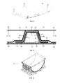
- FIG. 5 is a schematic cross-section view of the assembly of the fan-cowl components before the curing step.
- FIG. 6 is a perspective view of the tooling used for curing the fan-cowl assembly.
- the structural components of the curvilinear fan cowl 11 of an aircraft engine according to the embodiment shown in the FIGS. 1-4 are a skin 13 , transverse frames 15 with an omega-shaped cross-section and longitudinal beams 17 , 19 (parallel to the longitudinal axis of the aircraft) with an I shaped cross-section except for the parts to be superimposed to the transverse frames 15 .
- the configuration of the caps of the longitudinal beams 17 , 19 in their crossing zones with the transverse frames 15 is adapted for being used as union areas of fittings of the engine.
- the transverse frames 15 are equally spaced in the longitudinal direction of the fan cowl 11 , two longitudinal beams 17 are placed over the transverse frames 15 in the upper and lower ends of the fan cowl 11 and three longitudinal beams 19 are placed over two transverse frames 15 in inner zones of the fan cowl 11 .
- the longitudinal beams 17 , 19 comprise first parts 21 in their crossing zones with the transverse frames 15 and second parts 23 in the rest of their length, having their webs arranged in a same plane.
- the longitudinal beams 17 comprise four first parts 21 and three second parts 23 while the longitudinal beams 19 comprise two first parts 21 and one second part 23 (see FIG. 1 ).
- the first parts 21 of the longitudinal beams 17 , 19 comprise a cap 31 , two webs 30 , 30 ′ and two feet 34 , 34 ′ having a cross-section of an omega shape to be superimposed to the transverse frames 15 and the second parts 23 comprise a central portion 25 and two end portions 27 with webs 41 .
- the caps 31 of the first parts 21 are not symmetric with respect to the plane 40 of the webs 41 of the second parts 23 . They have a first area of width W 1 at one side of the plane 40 of the webs 41 and a second area of width W 2 at the other side, being W 2 >W 1 .
- the central portion 25 of the second parts 23 is symmetric with respect to its web 41 . It has a cap 42 and a foot 44 of a constant width W 3 .
- a longitudinal beam 17 can have a second part 23 with a central portion of a variable height to attend specific requirements.
- a central portion 25 can include ribs 50 as reinforcing elements in particularly loaded zones such as zones with fittings transmitting loads from external elements.
- the end portions 27 of the second parts 23 are not symmetric with respect to the plane 40 of their webs 41 .
- the caps 37 of the end portions 27 have a variable width for accommodating the change in width between the caps 42 of the central portions 25 of the second parts 23 and the caps 31 of the first parts 21 .
- the widening of the caps 37 are concentrated towards the second area of the first parts 21 .
- the caps 37 include a recess 38 .
- the method of manufacturing the curvilinear fan cowl 11 of aircraft engines according to the present invention involves manufacturing separately the skin 13 , the transverse frames 15 , the longitudinal beams 17 , 19 and the assembly of said components in the sequence illustrated in FIG. 1 .
- the transverse frames 15 and the longitudinal beams 17 , 19 are provided to the assembly stage in a cured state and the skin 13 in an uncured state.
- the skin 13 can be manufactured by a manufacturing method comprising the following steps:
- the transverse frames 15 and the longitudinal beams 17 , 19 can be manufactured by any suitable CFRP (“Carbon Fiber Reinforced Plastic”) manufacturing method and, particularly, by a Resin Transfer Moulding (RTM) method for achieving a good dimensional control.
- CFRP Carbon Fiber Reinforced Plastic
- RTM Resin Transfer Moulding
- the assembly stage may also comprise laying-up local patches of glass fiber prepreg at specific locations of the skin 13 , the transverse frames 15 and the longitudinal beams 17 , 19 where aluminum fittings are going to be installed.
Landscapes
- Engineering & Computer Science (AREA)
- Mechanical Engineering (AREA)
- Aviation & Aerospace Engineering (AREA)
- Architecture (AREA)
- Civil Engineering (AREA)
- Structural Engineering (AREA)
- Chemical & Material Sciences (AREA)
- Composite Materials (AREA)
- General Engineering & Computer Science (AREA)
- Moulding By Coating Moulds (AREA)
Abstract
Description
-
- Automate fiber-placement of carbon fiber prepreg on a cylindrical mandrel.
- Lay-up of additional layers for lightning protection and/or erosion and/or impact protection.
- Unloading the
skin 13 from the mandrel (the skins for the left and right fan-cowls can be made at the same time and then separated by a cutting method before unloading from the mandrel) for being located in thetool 61 used in the assembly stage of thefan cowl 11.
-
- The
skin 13 with ametallic mesh 57 in its outer face is located on theautoclave tool 61. - An
adhesive layer 51 is laid-up on the inner faces of thetransverse frames 15 in contact with theskin 13. - The
transverse frames 15, comprising acap 12, twowebs feet internal vacuum bag 49, are located over theskin 13 using a special bridge tooling (not shown) for controlling their position. - A
shim layer 55 with an adhesive ply over it is laid-up over thetransverse frames 15 in the overlapping regions with the longitudinal frames to cover possible gaps between them due to tolerances. - An
adhesive layer 53 is laid-up on the inner face of thelongitudinal beams skin 13. - The
longitudinal beams - A vacuum bag (not shown) is disposed over the assembly.
- An autoclave curing cycle at predetermined conditions of pressure and temperature is performed. In this step the
skin 13 is co-bonded with thetransverse frames 15 and thelongitudinal beams longitudinal beams
- The
Claims (17)
Applications Claiming Priority (3)
| Application Number | Priority Date | Filing Date | Title |
|---|---|---|---|
| EP13382070 | 2013-03-04 | ||
| EP13382070.4 | 2013-03-04 | ||
| EP13382070.4A EP2774854B1 (en) | 2013-03-04 | 2013-03-04 | An improved monolithic fan cowl of an aircraft engine and a manufacturing method thereof |
Publications (2)
| Publication Number | Publication Date |
|---|---|
| US20140248143A1 US20140248143A1 (en) | 2014-09-04 |
| US9677409B2 true US9677409B2 (en) | 2017-06-13 |
Family
ID=47913351
Family Applications (1)
| Application Number | Title | Priority Date | Filing Date |
|---|---|---|---|
| US14/196,330 Active 2035-06-14 US9677409B2 (en) | 2013-03-04 | 2014-03-04 | Monolithic fan cowl of an aircraft engine and a manufacturing method thereof |
Country Status (3)
| Country | Link |
|---|---|
| US (1) | US9677409B2 (en) |
| EP (1) | EP2774854B1 (en) |
| ES (1) | ES2635122T3 (en) |
Cited By (1)
| Publication number | Priority date | Publication date | Assignee | Title |
|---|---|---|---|---|
| US20240270397A1 (en) * | 2021-09-02 | 2024-08-15 | Rohr, Inc. | Corrugated stiffening devices utilizing peaks and valleys and methods of manufacture |
Families Citing this family (6)
| Publication number | Priority date | Publication date | Assignee | Title |
|---|---|---|---|---|
| US11059206B2 (en) * | 2016-02-05 | 2021-07-13 | Rohr, Inc | Method for fabricating composite structures using combined resin film and dry fabric |
| US10479517B2 (en) * | 2016-12-05 | 2019-11-19 | The Boeing Company | Composite fan cowl with a core having tailored thickness |
| CN114060305B (en) * | 2020-07-29 | 2024-07-12 | 中国航发商用航空发动机有限责任公司 | Fan containing casing and preparation method thereof |
| IT202000032414A1 (en) * | 2020-12-24 | 2022-06-24 | Aeronautical Service S R L | AIRCRAFT DOOR AND PRODUCTION METHOD. |
| FR3121660B1 (en) * | 2021-04-12 | 2023-04-14 | Safran Nacelles | Curved stiffener for a turbomachine nacelle and method of manufacturing such a stiffener |
| DE102022206242A1 (en) | 2022-06-22 | 2023-12-28 | Rolls-Royce Deutschland Ltd & Co Kg | Method for producing an engine component from at least one fiber-reinforced plastic |
Citations (9)
| Publication number | Priority date | Publication date | Assignee | Title |
|---|---|---|---|---|
| US4471609A (en) | 1982-08-23 | 1984-09-18 | The Boeing Company | Apparatus and method for minimizing engine backbone bending |
| US5297765A (en) * | 1992-11-02 | 1994-03-29 | Rohr, Inc. | Turbine engine nacelle laminar flow control arrangement |
| FR2771331A1 (en) | 1997-11-21 | 1999-05-28 | Aerospatiale | Aircraft panel |
| WO1999026841A1 (en) | 1997-11-26 | 1999-06-03 | Aerospatiale Societe Nationale Industrielle | Method for making a composite panel and resulting panel |
| US6358014B1 (en) * | 2000-03-24 | 2002-03-19 | General Electric Company | Composite spinner and method of making the same |
| US6458309B1 (en) * | 1998-06-01 | 2002-10-01 | Rohr, Inc. | Method for fabricating an advanced composite aerostructure article having an integral co-cured fly away hollow mandrel |
| EP1707344A1 (en) | 2005-03-30 | 2006-10-04 | Eads Construcciones Aeronauticas S.A. | Process for manufacturing a monolithic fan cowl |
| US20120001023A1 (en) | 2010-06-30 | 2012-01-05 | Airbus Operations, S.L. | Aircraft fuselage made out with composite material and manufacturing processes |
| DE102011012319A1 (en) | 2011-02-25 | 2012-08-30 | Daimler Ag | Method for joining a component made of a fiber-reinforced composite material with a component made of a metal and connecting arrangement of such components |
-
2013
- 2013-03-04 ES ES13382070.4T patent/ES2635122T3/en active Active
- 2013-03-04 EP EP13382070.4A patent/EP2774854B1/en active Active
-
2014
- 2014-03-04 US US14/196,330 patent/US9677409B2/en active Active
Patent Citations (13)
| Publication number | Priority date | Publication date | Assignee | Title |
|---|---|---|---|---|
| US4471609A (en) | 1982-08-23 | 1984-09-18 | The Boeing Company | Apparatus and method for minimizing engine backbone bending |
| US5297765A (en) * | 1992-11-02 | 1994-03-29 | Rohr, Inc. | Turbine engine nacelle laminar flow control arrangement |
| FR2771331A1 (en) | 1997-11-21 | 1999-05-28 | Aerospatiale | Aircraft panel |
| US6479124B1 (en) * | 1997-11-21 | 2002-11-12 | Aerospatiale Societe Nationale Industrielle | Composite material panel with shock-protected edges |
| WO1999026841A1 (en) | 1997-11-26 | 1999-06-03 | Aerospatiale Societe Nationale Industrielle | Method for making a composite panel and resulting panel |
| US6375121B1 (en) | 1997-11-26 | 2002-04-23 | Aerospatiale Societe Nationale Industrielle | Method for making a composite panel and resulting panel |
| US6458309B1 (en) * | 1998-06-01 | 2002-10-01 | Rohr, Inc. | Method for fabricating an advanced composite aerostructure article having an integral co-cured fly away hollow mandrel |
| US6358014B1 (en) * | 2000-03-24 | 2002-03-19 | General Electric Company | Composite spinner and method of making the same |
| EP1707344A1 (en) | 2005-03-30 | 2006-10-04 | Eads Construcciones Aeronauticas S.A. | Process for manufacturing a monolithic fan cowl |
| US20060290028A1 (en) * | 2005-03-30 | 2006-12-28 | Eads Construcciones Aeronauticas, S.A. | Process for manufacturing a monolithic fan cowl |
| US20120001023A1 (en) | 2010-06-30 | 2012-01-05 | Airbus Operations, S.L. | Aircraft fuselage made out with composite material and manufacturing processes |
| DE102011012319A1 (en) | 2011-02-25 | 2012-08-30 | Daimler Ag | Method for joining a component made of a fiber-reinforced composite material with a component made of a metal and connecting arrangement of such components |
| WO2012113426A1 (en) * | 2011-02-25 | 2012-08-30 | Daimler Ag | Method of joining a component composed of a carbon fibre-reinforced composite to a component comprised of a metal and bonding arrangement of such components |
Non-Patent Citations (1)
| Title |
|---|
| European Search Report dated Jul. 5, 2013 in EP 13382070.4. |
Cited By (1)
| Publication number | Priority date | Publication date | Assignee | Title |
|---|---|---|---|---|
| US20240270397A1 (en) * | 2021-09-02 | 2024-08-15 | Rohr, Inc. | Corrugated stiffening devices utilizing peaks and valleys and methods of manufacture |
Also Published As
| Publication number | Publication date |
|---|---|
| EP2774854A1 (en) | 2014-09-10 |
| ES2635122T3 (en) | 2017-10-02 |
| US20140248143A1 (en) | 2014-09-04 |
| EP2774854B1 (en) | 2017-05-03 |
Similar Documents
| Publication | Publication Date | Title |
|---|---|---|
| US9677409B2 (en) | Monolithic fan cowl of an aircraft engine and a manufacturing method thereof | |
| CA2714175C (en) | Method for manufacturing a fibre-composite component, fibre-composite component and fibre-composite fuselage component of an aircraft | |
| US8096504B2 (en) | Integrated aircraft structure in composite material | |
| JP5801885B2 (en) | Composite structure having integral stiffener and method for producing the same | |
| US8651419B2 (en) | Flexible truss frame and method of making the same | |
| US8079549B2 (en) | Monolithic integrated structural panels especially useful for aircraft structures | |
| US9284035B2 (en) | Composite tubular-reinforced integrated structural panels with mutually intersecting stiffeners and fabrication processes | |
| EP2749491B1 (en) | Aircraft structure with integrated reinforcing elements | |
| EP2865516B1 (en) | Skin-stiffened composite panel and method of its manufacture | |
| EP2889211B1 (en) | Aircraft structure made of composite material | |
| EP2343237B1 (en) | Aircraft fuselage frame in composite material with stabilized web | |
| EP3483057B1 (en) | Reinforcing arrangement for an opening in an aircraft structure | |
| US11220354B2 (en) | Composite fuselage assembly and methods to form the assembly | |
| KR20140100882A (en) | Method and system of making composite structures having gap fillers with chopped fiber material | |
| US20110206875A1 (en) | Method and arrangement for production of an integral hollow-profiled component with fibre composite material | |
| EP3597525B1 (en) | Curved composite part and manufacturing method thereof | |
| US20110311782A1 (en) | Planar component of an aircraft and method for producing the same | |
| JP2023539418A (en) | Process for manufacturing structural components in composite materials stiffened with at least one stringer | |
| ES2981087T3 (en) | Manufacturing process for a rear section of an aircraft and a rear section of an aircraft manufactured according to said process | |
| CN103687788B (en) | a composite frame |
Legal Events
| Date | Code | Title | Description |
|---|---|---|---|
| AS | Assignment |
Owner name: EADS CONSTRUCCIONES AERONAUTICAS S.A., SPAIN Free format text: ASSIGNMENT OF ASSIGNORS INTEREST;ASSIGNORS:DEL CERRO, ALVARO ORTIZ;PLEITE, JOAQUIN GALLEGO;GARCIA, LUIS RUBIO;AND OTHERS;REEL/FRAME:034840/0346 Effective date: 20140304 |
|
| FEPP | Fee payment procedure |
Free format text: PAYOR NUMBER ASSIGNED (ORIGINAL EVENT CODE: ASPN); ENTITY STATUS OF PATENT OWNER: LARGE ENTITY |
|
| STCF | Information on status: patent grant |
Free format text: PATENTED CASE |
|
| MAFP | Maintenance fee payment |
Free format text: PAYMENT OF MAINTENANCE FEE, 4TH YEAR, LARGE ENTITY (ORIGINAL EVENT CODE: M1551); ENTITY STATUS OF PATENT OWNER: LARGE ENTITY Year of fee payment: 4 |
|
| MAFP | Maintenance fee payment |
Free format text: PAYMENT OF MAINTENANCE FEE, 8TH YEAR, LARGE ENTITY (ORIGINAL EVENT CODE: M1552); ENTITY STATUS OF PATENT OWNER: LARGE ENTITY Year of fee payment: 8 |