US965967A - Double-acting spring-hinge. - Google Patents
Double-acting spring-hinge. Download PDFInfo
- Publication number
- US965967A US965967A US55056910A US1910550569A US965967A US 965967 A US965967 A US 965967A US 55056910 A US55056910 A US 55056910A US 1910550569 A US1910550569 A US 1910550569A US 965967 A US965967 A US 965967A
- Authority
- US
- United States
- Prior art keywords
- spindle
- door
- shoe
- hinge
- double
- Prior art date
- Legal status (The legal status is an assumption and is not a legal conclusion. Google has not performed a legal analysis and makes no representation as to the accuracy of the status listed.)
- Expired - Lifetime
Links
- 230000008878 coupling Effects 0.000 description 1
- 238000010168 coupling process Methods 0.000 description 1
- 238000005859 coupling reaction Methods 0.000 description 1
- 230000000994 depressogenic effect Effects 0.000 description 1
- 239000002023 wood Substances 0.000 description 1
Images

Classifications
-
- E—FIXED CONSTRUCTIONS
- E05—LOCKS; KEYS; WINDOW OR DOOR FITTINGS; SAFES
- E05F—DEVICES FOR MOVING WINGS INTO OPEN OR CLOSED POSITION; CHECKS FOR WINGS; WING FITTINGS NOT OTHERWISE PROVIDED FOR, CONCERNED WITH THE FUNCTIONING OF THE WING
- E05F1/00—Closers or openers for wings, not otherwise provided for in this subclass
- E05F1/08—Closers or openers for wings, not otherwise provided for in this subclass spring-actuated, e.g. for horizontally sliding wings
- E05F1/10—Closers or openers for wings, not otherwise provided for in this subclass spring-actuated, e.g. for horizontally sliding wings for swinging wings, e.g. counterbalance
- E05F1/12—Mechanisms in the shape of hinges or pivots, operated by springs
- E05F1/1207—Mechanisms in the shape of hinges or pivots, operated by springs with a coil spring parallel with the pivot axis
- E05F1/1215—Mechanisms in the shape of hinges or pivots, operated by springs with a coil spring parallel with the pivot axis with a canted-coil torsion spring
Definitions
- My invention relates to improvements in double swing spring hinges, so-called, the object being to provide simple and effective support, together with means for releasing the door so that it may be held ajar by the same spring that would ordinarily operate to close the same.
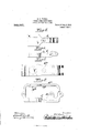
- Figure 1 is a horizontal section of a portion of a door and part of my mechanism, other parts of the latter being shown in plan.
- Fig. 2 is a side elevation of my invention as applied to a door, the latter being partly broken away and one of the cover plates removed.
- Figs. 3, 4, 5 and 6 are detail views of various parts shown in Figs. 1 and 2.
- 1 represents a part of a door.
- 2 repre sents a spindle mounted in a housing 3 and controlled by a spring in any suitable way in such manner that such spindle 2 is restored to a normal position after being turned in either direction away from said normal position.
- Spring devices for restoring spindles such as 2 are so well known as to require no detailed description, it being merely sufiicient to state broadly that the spindle 2 is spring-controlled.
- the housing 3 is ordinarily placed in the door sill or threshold adjacent to one side of the door casing, so that the spindle 2 will project into the lower edge of the door.
- a suit able spindle support (not shown) is provided in the upper part of the door casing directly above the spindle 2. The parts thus far referred to are well understood and require no further description.
- lever connection 6 is a lever connection pivoted at 7 in a boss 8 formed on the upper side of the shoe 4.
- This lever connection has a rectangular passage at its forward end arranged to fit over the squared part 5 of the spindle.
- 10 is a spring operating to move said lever 6 in a direction to normally engage the squared part of the spindle 5.
- 1112 are cover plates at the opposite sides of the door, the same being rigidly held in place preferably by screws 18, which preferably take into parts of the shoe 4, whereby all of the parts are held together.
- These plates are provided with suitable clearance slits for the pin 10, whereby said pin may be depressed by the foot for the purpose of lifting the opposite end of the lever 6 so as to disconnect the same from the squared part 5 of the spindle 2, as indicated in dotted lines Fig. 2.
- the plates 11 and 12 serving to hold the same in place being preferably made of sufliciently heavy stock to perform that function.
- the plates 11-l2 may, of course, be secured to the door in any suitable manner, as by ordinary wood screws, certain parts of said plates, of course, overstanding a part of the door adjacent the notch.
- a hinge pivot or spindle a shoe adapted thereto and a part carried by said shoe arranged to rest upon and be supported by the upper end of said spindle whereby said shoe may turn independently of and on said spindle, and means for coupling said shoe with and uncoupling the same from said spindle.
- a hinge pivot or spindle a shoe having a passage for said spindle, in which the latter may rotate, and an upwardly arched extension, said extension overstanding the upper end of said spindle and arranged to operate as a bearing therefor, a manually operable locking device arranged in the space between the shoe and said extension, whereby said shoe may be coupled to or uncoupled from said spindle for rotation.
Landscapes
- Closing And Opening Devices For Wings, And Checks For Wings (AREA)
- Hinges (AREA)
Description
Patented Aug.2,1910.
2 SHEETS-SHEET 1.
Qmi/fmmeo H. G. VOIGHT. DOUBLE ACTING SPRING HINGE. APPLIOATION FILED MAR. 21, 1910.
965,967. Patented Aug. 2, 1910.
2 SHEETS-SHEET 2.
'nnirnn sra rns PATENT oFFIcE.
HENRY G. VOIGHT, OF NEW BRITAIN, CONNECTICUT, ASSIGNOR TO RUSSELL & ERWIN MANUFACTURING COMPANY, OF NEW BRITAIN, CONNECTICUT, A CORPORATION OF CONNECTICUT.
DOUBLE-ACTING SPRING-HINGE.
To all whom it may concern:
Be it known that I, HENRY G. VOIGHT, a citizen of the United States, residing at New Britain, county of Hartford, State of Connecticut, have invented certain new and useful Improvements in Double-Acting Spring-Hinges, of which the following is a full, clear, and exact description.
My invention relates to improvements in double swing spring hinges, so-called, the object being to provide simple and effective support, together with means for releasing the door so that it may be held ajar by the same spring that would ordinarily operate to close the same.
In the accompanying drawings Figure 1 is a horizontal section of a portion of a door and part of my mechanism, other parts of the latter being shown in plan. Fig. 2 is a side elevation of my invention as applied to a door, the latter being partly broken away and one of the cover plates removed. Figs. 3, 4, 5 and 6 are detail views of various parts shown in Figs. 1 and 2.
1 represents a part of a door. 2 repre sents a spindle mounted in a housing 3 and controlled by a spring in any suitable way in such manner that such spindle 2 is restored to a normal position after being turned in either direction away from said normal position. Spring devices for restoring spindles such as 2 are so well known as to require no detailed description, it being merely sufiicient to state broadly that the spindle 2 is spring-controlled. The housing 3 is ordinarily placed in the door sill or threshold adjacent to one side of the door casing, so that the spindle 2 will project into the lower edge of the door. A suit able spindle support (not shown) is provided in the upper part of the door casing directly above the spindle 2. The parts thus far referred to are well understood and require no further description.
4 is what I may term a shoe support arranged to be let into a notch or recess in the lower edge of the door and suitably secured therein in any desired manner. The lower part of this shoe is provided with a passage for the spindle 2.
4 is an upward arched extension from the shoe 4, the same having a bearing 4" arranged to rest upon the upper end of the spindle 2 so as to support the door. The
Specification of Letters Patent.
Application filed. March 21, 1910.
Patented Aug. 2, 1910.
Serial No. 550,559.
6 is a lever connection pivoted at 7 in a boss 8 formed on the upper side of the shoe 4. This lever connection has a rectangular passage at its forward end arranged to fit over the squared part 5 of the spindle. 10 is a spring operating to move said lever 6 in a direction to normally engage the squared part of the spindle 5.
9 is a laterally projecting pin at the rear end of the lever 6, the ends of said pin projecting preferably on both sides of the door 1.
1112 are cover plates at the opposite sides of the door, the same being rigidly held in place preferably by screws 18, which preferably take into parts of the shoe 4, whereby all of the parts are held together. These plates are provided with suitable clearance slits for the pin 10, whereby said pin may be depressed by the foot for the purpose of lifting the opposite end of the lever 6 so as to disconnect the same from the squared part 5 of the spindle 2, as indicated in dotted lines Fig. 2.
By the arrangement shown herein it is merely necessary to saw a notch in the lower edge of the door to receive the shoe 4 and its associated parts, the plates 11 and 12 serving to hold the same in place being preferably made of sufliciently heavy stock to perform that function. The plates 11-l2 may, of course, be secured to the door in any suitable manner, as by ordinary wood screws, certain parts of said plates, of course, overstanding a part of the door adjacent the notch.
From the foregoing it will be seen that when the parts are properly set up, the door receives its lower support upon the spindle 2, which is so placed that in its normal position it will, through the medium of the lever 6, serve to hold the door closed. Whenever the door is swung to the right or left with the lever connections 6 in the position shown in solid lines, Fig. 2) it will be returned by the spring-controlled spindle 2. If, however, it is desired to open the door and to permit it to stand ajar, the operator merely places his or her foot upon the pin 9, disconnecting the lever 6 from the squared part of the spindle 2. The door is then swung to the open position at right angles to the closed position, whereupon on releasing the pressure on the pin 9, the spring 10 restores the lever 6 to the spindle engaging position, in which position the door is held ajar so long as desired. By this very simple means, a double swing self-closing hinge is so constructed that the door may be held ajar whenever desired, without the necessity of employing auxiliary means such as door stops and the like.
\Vhat I claim is:
1. In a device of the character described, a hinge pivot or spindle, a shoe adapted thereto and a part carried by said shoe arranged to rest upon and be supported by the upper end of said spindle whereby said shoe may turn independently of and on said spindle, and means for coupling said shoe with and uncoupling the same from said spindle.
2. In a device of the character described, a hinge pivot or spindle, a shoe having a passage for said spindle, in which the latter may rotate, and an upwardly arched extension, said extension overstanding the upper end of said spindle and arranged to operate as a bearing therefor, a manually operable locking device arranged in the space between the shoe and said extension, whereby said shoe may be coupled to or uncoupled from said spindle for rotation.
HENRY G. VOIGHT. \Vitnesses:
M. S. VVIARD, H. J. BROWNE.
Priority Applications (1)
| Application Number | Priority Date | Filing Date | Title |
|---|---|---|---|
| US55056910A US965967A (en) | 1910-03-21 | 1910-03-21 | Double-acting spring-hinge. |
Applications Claiming Priority (1)
| Application Number | Priority Date | Filing Date | Title |
|---|---|---|---|
| US55056910A US965967A (en) | 1910-03-21 | 1910-03-21 | Double-acting spring-hinge. |
Publications (1)
| Publication Number | Publication Date |
|---|---|
| US965967A true US965967A (en) | 1910-08-02 |
Family
ID=3034362
Family Applications (1)
| Application Number | Title | Priority Date | Filing Date |
|---|---|---|---|
| US55056910A Expired - Lifetime US965967A (en) | 1910-03-21 | 1910-03-21 | Double-acting spring-hinge. |
Country Status (1)
| Country | Link |
|---|---|
| US (1) | US965967A (en) |
-
1910
- 1910-03-21 US US55056910A patent/US965967A/en not_active Expired - Lifetime
Similar Documents
| Publication | Publication Date | Title |
|---|---|---|
| US920961A (en) | Latch. | |
| US1176014A (en) | Liquid door-check and spring. | |
| US1171979A (en) | Device for operating transoms and casements. | |
| US993002A (en) | Double-acting floor-hinge. | |
| US1313726A (en) | Hinge | |
| US1202259A (en) | Door control. | |
| US1095682A (en) | Casement-window operator. | |
| US413298A (en) | Latch-hinge | |
| US1324381A (en) | Door-bolt | |
| US976138A (en) | Door-stop. | |
| US892514A (en) | Safe, vault, &c. | |
| US1084387A (en) | Type-writer desk or stand. | |
| US629247A (en) | Door-check. | |
| US1289828A (en) | Casement-adjuster. | |
| US1171690A (en) | Latch-operating device. | |
| US712511A (en) | Door opening or closing mechanism. | |
| US970445A (en) | Door-check. | |
| US402493A (en) | Latch for sliding doors | |
| US216843A (en) | Improvement in devices for opening safe-doors | |
| US802063A (en) | Transom-opener. | |
| US278783A (en) | downes | |
| US497730A (en) | Lock-hinge | |
| US1035719A (en) | Transom-lift. | |
| US927340A (en) | Double-acting spring-hinge. | |
| US1124940A (en) | Door-operating mechanism. |