US9648692B2 - Portable lamp comprising a contact-less control device - Google Patents
Portable lamp comprising a contact-less control device Download PDFInfo
- Publication number
- US9648692B2 US9648692B2 US14/692,954 US201514692954A US9648692B2 US 9648692 B2 US9648692 B2 US 9648692B2 US 201514692954 A US201514692954 A US 201514692954A US 9648692 B2 US9648692 B2 US 9648692B2
- Authority
- US
- United States
- Prior art keywords
- proximity
- lamp
- move
- switching
- controlling
- Prior art date
- Legal status (The legal status is an assumption and is not a legal conclusion. Google has not performed a legal analysis and makes no representation as to the accuracy of the status listed.)
- Active
Links
Images


Classifications
-
- H—ELECTRICITY
- H05—ELECTRIC TECHNIQUES NOT OTHERWISE PROVIDED FOR
- H05B—ELECTRIC HEATING; ELECTRIC LIGHT SOURCES NOT OTHERWISE PROVIDED FOR; CIRCUIT ARRANGEMENTS FOR ELECTRIC LIGHT SOURCES, IN GENERAL
- H05B45/00—Circuit arrangements for operating light-emitting diodes [LED]
- H05B45/20—Controlling the colour of the light
-
- H05B33/0854—
-
- F—MECHANICAL ENGINEERING; LIGHTING; HEATING; WEAPONS; BLASTING
- F21—LIGHTING
- F21L—LIGHTING DEVICES OR SYSTEMS THEREOF, BEING PORTABLE OR SPECIALLY ADAPTED FOR TRANSPORTATION
- F21L4/00—Electric lighting devices with self-contained electric batteries or cells
-
- F—MECHANICAL ENGINEERING; LIGHTING; HEATING; WEAPONS; BLASTING
- F21—LIGHTING
- F21V—FUNCTIONAL FEATURES OR DETAILS OF LIGHTING DEVICES OR SYSTEMS THEREOF; STRUCTURAL COMBINATIONS OF LIGHTING DEVICES WITH OTHER ARTICLES, NOT OTHERWISE PROVIDED FOR
- F21V21/00—Supporting, suspending, or attaching arrangements for lighting devices; Hand grips
- F21V21/08—Devices for easy attachment to any desired place, e.g. clip, clamp, magnet
- F21V21/084—Head fittings
-
- F—MECHANICAL ENGINEERING; LIGHTING; HEATING; WEAPONS; BLASTING
- F21—LIGHTING
- F21V—FUNCTIONAL FEATURES OR DETAILS OF LIGHTING DEVICES OR SYSTEMS THEREOF; STRUCTURAL COMBINATIONS OF LIGHTING DEVICES WITH OTHER ARTICLES, NOT OTHERWISE PROVIDED FOR
- F21V23/00—Arrangement of electric circuit elements in or on lighting devices
- F21V23/04—Arrangement of electric circuit elements in or on lighting devices the elements being switches
- F21V23/0414—Arrangement of electric circuit elements in or on lighting devices the elements being switches specially adapted to be used with portable lighting devices
-
- F—MECHANICAL ENGINEERING; LIGHTING; HEATING; WEAPONS; BLASTING
- F21—LIGHTING
- F21V—FUNCTIONAL FEATURES OR DETAILS OF LIGHTING DEVICES OR SYSTEMS THEREOF; STRUCTURAL COMBINATIONS OF LIGHTING DEVICES WITH OTHER ARTICLES, NOT OTHERWISE PROVIDED FOR
- F21V23/00—Arrangement of electric circuit elements in or on lighting devices
- F21V23/04—Arrangement of electric circuit elements in or on lighting devices the elements being switches
- F21V23/0442—Arrangement of electric circuit elements in or on lighting devices the elements being switches activated by means of a sensor, e.g. motion or photodetectors
- F21V23/0471—Arrangement of electric circuit elements in or on lighting devices the elements being switches activated by means of a sensor, e.g. motion or photodetectors the sensor detecting the proximity, the presence or the movement of an object or a person
-
- H05B33/0863—
-
- H05B37/0227—
-
- H—ELECTRICITY
- H05—ELECTRIC TECHNIQUES NOT OTHERWISE PROVIDED FOR
- H05B—ELECTRIC HEATING; ELECTRIC LIGHT SOURCES NOT OTHERWISE PROVIDED FOR; CIRCUIT ARRANGEMENTS FOR ELECTRIC LIGHT SOURCES, IN GENERAL
- H05B47/00—Circuit arrangements for operating light sources in general, i.e. where the type of light source is not relevant
- H05B47/10—Controlling the light source
- H05B47/105—Controlling the light source in response to determined parameters
-
- F—MECHANICAL ENGINEERING; LIGHTING; HEATING; WEAPONS; BLASTING
- F21—LIGHTING
- F21W—INDEXING SCHEME ASSOCIATED WITH SUBCLASSES F21K, F21L, F21S and F21V, RELATING TO USES OR APPLICATIONS OF LIGHTING DEVICES OR SYSTEMS
- F21W2111/00—Use or application of lighting devices or systems for signalling, marking or indicating, not provided for in codes F21W2102/00 – F21W2107/00
- F21W2111/10—Use or application of lighting devices or systems for signalling, marking or indicating, not provided for in codes F21W2102/00 – F21W2107/00 for personal use, e.g. hand-held
-
- F—MECHANICAL ENGINEERING; LIGHTING; HEATING; WEAPONS; BLASTING
- F21—LIGHTING
- F21W—INDEXING SCHEME ASSOCIATED WITH SUBCLASSES F21K, F21L, F21S and F21V, RELATING TO USES OR APPLICATIONS OF LIGHTING DEVICES OR SYSTEMS
- F21W2131/00—Use or application of lighting devices or systems not provided for in codes F21W2102/00-F21W2121/00
- F21W2131/40—Lighting for industrial, commercial, recreational or military use
-
- F—MECHANICAL ENGINEERING; LIGHTING; HEATING; WEAPONS; BLASTING
- F21—LIGHTING
- F21Y—INDEXING SCHEME ASSOCIATED WITH SUBCLASSES F21K, F21L, F21S and F21V, RELATING TO THE FORM OR THE KIND OF THE LIGHT SOURCES OR OF THE COLOUR OF THE LIGHT EMITTED
- F21Y2101/00—Point-like light sources
-
- F—MECHANICAL ENGINEERING; LIGHTING; HEATING; WEAPONS; BLASTING
- F21—LIGHTING
- F21Y—INDEXING SCHEME ASSOCIATED WITH SUBCLASSES F21K, F21L, F21S and F21V, RELATING TO THE FORM OR THE KIND OF THE LIGHT SOURCES OR OF THE COLOUR OF THE LIGHT EMITTED
- F21Y2115/00—Light-generating elements of semiconductor light sources
- F21Y2115/10—Light-emitting diodes [LED]
-
- Y—GENERAL TAGGING OF NEW TECHNOLOGICAL DEVELOPMENTS; GENERAL TAGGING OF CROSS-SECTIONAL TECHNOLOGIES SPANNING OVER SEVERAL SECTIONS OF THE IPC; TECHNICAL SUBJECTS COVERED BY FORMER USPC CROSS-REFERENCE ART COLLECTIONS [XRACs] AND DIGESTS
- Y02—TECHNOLOGIES OR APPLICATIONS FOR MITIGATION OR ADAPTATION AGAINST CLIMATE CHANGE
- Y02B—CLIMATE CHANGE MITIGATION TECHNOLOGIES RELATED TO BUILDINGS, e.g. HOUSING, HOUSE APPLIANCES OR RELATED END-USER APPLICATIONS
- Y02B20/00—Energy efficient lighting technologies, e.g. halogen lamps or gas discharge lamps
- Y02B20/40—Control techniques providing energy savings, e.g. smart controller or presence detection
-
- Y02B20/44—
Definitions
- the present invention relates to the field of portable electric lamps and in particular a headlamp fitted with a contact less control of brightness of the light beam.
- a portable lamp having a control of the light power which comprises:
- the direction of movement of the object is used by the control module for the purpose of determining whether to increment or decrement the level of intensity of the luminous flux, whereby the user may position the lamp on his head without taking care of the right side of the positioning of the lamp.
- all proximity detectors are located on a same axis X-X′ at one side of said light source.
- the first proximity detectors comprise each an antenna configured for modifying the oscillation frequency of an oscillator when an object comes close to said detectors.
- the first proximity detectors can be based on an ultrasonic sensor configured for detecting the proximity of an object coming close to said lamp.
- the lamp comprises:
- the lamp comprises an electro-optical device being located in front of the light source, such as an electro-optical diffusion element providing an electric control of the transparency/opacity, and the second proximity detectors are configured for controlling the diffusion of the light beam.
- an electro-optical device being located in front of the light source, such as an electro-optical diffusion element providing an electric control of the transparency/opacity, and the second proximity detectors are configured for controlling the diffusion of the light beam.
- a Polymer Dispersed Liquid Crystal (PDLC) element performs the control of the diffusion of the light beam, wherein the PDLC element is controlled by said control module from information generated by said second proximity detectors detecting a move of an object along said axis Y-Y′.
- PDLC Polymer Dispersed Liquid Crystal
- the invention also achieves a process for controlling a portable lamp, comprising the steps:
- the invention is particularly adapted for the realization of a headlamp which switching-on/off may be easily controlled by a user irrespectively with the positioning side of the lamp on the user's head.
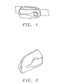
- FIG. 1 illustrates a perspective front view of an embodiment of a compact headlamp according to the invention.
- FIG. 2 shows a rear perspective view of the lamp of FIG. 1 , highlighting the USB port for charging the battery.
- FIG. 3 illustrates a first embodiment of a portable headlamp fitted with a contact less control of the power-on/off as well as the brightness of the light flux.
- FIG. 4 illustrates a second embodiment of a headlamp, wherein the proximity detection circuits are based on an antenna.
- FIG. 5 a shows an example of an electronic circuit used for embodying the proximity detector of the second embodiment.
- FIG. 5 b illustrates a third embodiment of a headlamp, wherein the proximity detectors are based on an ultrasonic sensor.
- FIGS. 6 a and 6 b illustrate respectively two examples of arrangement of the respective antennas of proximity detection devices along an axis XX′.
- FIG. 7 illustrates another example of an arrangement of antennas according to two axes XX′ and YY′, respectively perpendicular, so as to a achieve the detection of the movement of an object, along two perpendicular axes.
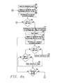
- FIGS. 8 a and 8 b illustrate an embodiment of a process for controlling the power-on, the adjustment of the brightness as well as the power-off of a headlamp fitted with proximity detectors.
- FIG. 9 illustrates a fourth embodiment of a headlamp further comprising a contact less control of the diffusion of the light beam.
- FIGS. 10 a and 10 b illustrate an embodiment of a process for controlling the light power but also the diffusion of the light beam.
- a portable lamp such as a headlamp which can advantageously incorporate an effective contact less control mechanism allowing not only to get rid of the conventional mechanical switches, but which can increase the robustness and the tightness of the lamp.
- USB Universal Serial Bus
- FIG. 3 illustrates the details of a first embodiment of a lamp which is shown in FIGS. 1 and 2 , and which achieves a contact less control of the power-on, the power-off and even the adjustment of light power.
- lamp 100 includes a power module 20 associated with a control module 10 and a light source 30 comprising one or more LED (s) with, where appropriate, their own focal systems.
- a single LED 31 together with its optical module 32 is represented.
- the LED 31 is powered via leads 33 connected to the power module 20 .
- Such arrangement clearly achieves quite a compact headlamp structure.
- the larger multi-chip-type LED (Cree XLM2), combined with less compact optical systems so as to achieve a more sophisticated headlamp structure.
- Power module 20 specifically includes all the components that are conventionally present in a LED light lamp for producing a light beam having a high intensity, and in general based on the Pulse Width Modulation (PWM), which is well known to the skilled person and which is similar to what is known in Class D audio circuits.
- PWM Pulse Width Modulation
- V c control signal
- control module 10 and power module 20 are integrated into a single module or integrated circuit.
- control signal V c when we refer to a “control signal V c ”, one equally contemplates the use of embodiments based on an electric control variable—current or voltage—as well as embodiments in which the control is performed by means of a logic information conveyed to the power module 20 . For this reason, we will discuss below indiscriminately control signal or control information.
- the components, switches and circuit, that make up power module 20 e.g. bipolar transistors, Field Effect Transistors (FET) or Metal Oxide Semiconductor (MOS) or Metal Oxide Semiconductor Field Effect transistors (MOSFET)—are well known to those skilled in the art and the description will be deliberately reduced in this regard for the sake of conciseness.
- FET Field Effect Transistors
- MOS Metal Oxide Semiconductor
- MOSFET Metal Oxide Semiconductor Field Effect transistors
- control module 10 has a microprocessor based architecture which comprises a processor 11 communicating via conventional address, data and control buses 19 with a memory device, for instance a Read Access Memory (RAM) 12 , a Flash memory 13 , a Read Only Memory (ROM) or Electrically Erasable Programmable Memory (EEPROM) etc. . . as well as input/output I/O circuits.
- RAM Read Access Memory
- Flash memory 13 Flash memory
- ROM Read Only Memory
- EEPROM Electrically Erasable Programmable Memory
- FIG. 3 illustrates one embodiment having two I/O circuits, respectively 14 and 15 , which may be combined, when appropriate, into a single circuit for interfacing, on one end, the power module 20 receiving control information V c and, on the other end, a set of n proximity detectors 50 - 1 , to 50 -n, with n being equal or greater than 2.
- the headlamp also includes a USB port (shown in FIG. 2 ) which can be accessed via a USB module 16 located within control module 10 , and which communicates with the address, data and control buses 19 .
- a USB control interface may serve, not only for recharging a battery (e.g. Li-Ion) 40 present in the headlamp, but also for the exchange of configuration data allowing the storing of adjustment parameters and profiles within the headlamp.
- the control module can communicate with a data processing system, such as a computer, a laptop, a touch pad, a personal assistant and even a conventional smart phone for the purpose of configuring the headlamp.
- a data processing system such as a computer, a laptop, a touch pad, a personal assistant and even a conventional smart phone for the purpose of configuring the headlamp.
- the USB port is only an illustrative example of the numerous possibilities of communication that may be used between the headlamp and a computer/touchpad/smartphone.
- the skilled person may consider the use of any other communications means, in particular wireless communications (bluetooth, wifi, etc. . . ).
- the headlamp stores its own Internet Protocol (IP) address so as to allow easy configuration, for instance via a dedicated web server.
- IP Internet Protocol
- Such communication is particularly advantageous especially for the exchange of configuration information, such as “profiles”, that may serve for storing within the headlamp memory, as appropriate, adjustments data and settings according to its intended use by its owner.
- configuration data can be stored within the headlamp to set a specific personalization of the control method described below, and in particular the parameters of the lamp setting window.
- the “profiles” may be used for allowing the activation of specific procedures or operating modes, including a so-called “reactive” or “dynamic” mode allowing automatic control of the brightness of the lamp, with a possibility to de-activate (static) or activate (dynamic) the regulation in accordance with the particular profile being selected.
- the proximity detectors 50 - 1 to 50 -n allow the detection of the proximity or vicinity of an object, such as a finger for example, being close to the headlamp.
- Each proximity detection circuit generate an information that is representative of such vicinity which is transmitted, respectively via circuits 54 - 1 to 54 -n, to the input/output module 15 located within control module 10 .
- control module 10 receives a set of data/information which are generated by the proximity detectors 50 - 1 to 50 -n, which information can be processed by means of suitable algorithms based on program code stored in its memory, so as to derive from such information the direction of movement of the object along a first axis XX′, particularly shown in FIGS. 6 a , 6 b and 7 , for the purpose of translating such movement into an effective power-on/off control instruction or an instruction for controlling the level of the brightness.
- FIG. 4 illustrates a second embodiment of a headlamp, wherein each proximity detector, for example proximity detector 50 - 1 (resp. 50 - 2 , . . . 50 -n) is based on an antenna 51 - 1 (respect. 51 - 2 , . . . 51 -n) connected to an oscillating circuit 52 - 1 (resp. 52 - 2 , . . . , 52 -n).
- the presence of a finger or any other object being close to the antenna 51 - 1 has the effect of lowering the frequency of oscillation of oscillator 52 - 1 (resp. 52 - 2 , . .
- FIG. 5 a particularly shows one practical embodiment of a proximity detector 50 - 1 which can be used in the second embodiment illustrated in FIG. 4 .
- antenna 51 - 1 is connected via a capacitor 101 to a first input of a NAND gate 102 —of the Schmidt Trigger type—whose second input is connected to a Vcc potential representative of a logic level “1”.
- a resistor 103 is connected between the first input of NAND gate 102 and its output so that that the combination of elements 101 - 103 achieve an oscillating circuit at a frequency determined by the product of the capacitance value 101 with the value of resistor 103 , for example of the order of 500 000 Hz.
- the output of NAND gate 102 is connected to the input of a frequency divider integrated circuit 104 for generating a square signal 120 having a lower frequency, for example of the order of a few hundred Hertz, which is then passed to the clock input (CK) of a flip-flop circuit 105 , whose D input is connected to the Vcc voltage, corresponding to a logic level “1”.
- the Q output of flip-flop 105 is connected to a first terminal of a resistor 106 and to the cathode of a diode 109 , whose anode is connected to a first terminal of a resistor 108 .
- the resistor 108 has a second terminal which is connected to the second terminal of resistor 106 and also to a first terminal of a capacitor 107 and to the reset input (reset) of latch 105 . Finally, the second terminal of capacitor 107 is connected to ground.
- Latch 105 includes a complementary output which connected to a first input of a NAND gate 110 whose second input receives the clock signal 120 generated by the output of the frequency divider integrated circuit 104 .
- Frequency divider circuit 104 generates at its output a square wave having a frequency of the order of several hundred Hertz, wherein the frequency decreases when an object such as a finger comes close to the antenna.
- the clock signal has a duty cycle of 50/50 with a high level during the first half of the cycle and a low level during the other half cycle. Consequently, during the first half of the cycle, the first input of NAND gate 110 is at a logic level 1. During the charging of capacitor 107 , the complementary output Q is at a low level, so that the output NAND gate 110 remains at a high state.
- the values of the components are selected so as to prevent, in a “normal situation” wherein no object is close to antenna 51 - 1 and thus detected—the reset of latch 105 during the first half of the cycle so that the output of NAND gate 110 is constantly at a high state.
- the oscillation frequency tends to decrease which, without changing the duty cycle, significantly increases the duration of the first half of the cycle during which the CK input clock is at a level 1.
- the combination of flip-flop 105 and NAND gate 110 achieves a frequency detector which allows the generation of a logical signal when the oscillation frequency falls sufficiently.
- this is only a specific example of an embodiment, which a skilled person may adapt and modify to fit multiple needs.
- FIG. 5 b shows a third embodiment which incorporates an ultrasonic sensor for determining whether an entity approaches close to the lamp, and this without requiring any mechanical contact.
- an ultrasonic transmitter 111 based on a piezoelectric transducer, generates ultrasonic waves that are reflected on a nearby object and which can be received by a receiver 112 generating a voltage representative of the received sound vibrations.
- the ultrasonic detectors can thus be used to determine the distance to an object or an entity on the basis of the estimate of the time between the sending of a acoustic wave and receiving an echo of the wave reflected by the object.
- a specific detection circuit 113 shown in FIG. 5 b can thus analyze the signal generated at the output of receiver 112 so as to derive information being representative of a detected object, which information can then be transmitted to the control module 10 via the conductor 54 - 1 .
- FIG. 5 b is, again, a particular non-limiting example and other embodiments may be envisaged by a skilled person, in particular based on the detection of a change a magnetic field or a change in the value of a variable capacitor etc. . . . .
- FIG. 6 a shows one possible arrangement of positions taken by a set of three antennas 51 - 1 , 51 - 2 and 51 - 3 on a headlamp 100 , and corresponding to as many (not shown) proximity detectors.
- the positions shown in FIG. 6 a are given only for illustration purposes and are generally not apparent on the final product on the market, which therefore shows a particularly attractive aesthetical design.
- control module 10 of FIG. 4 execute a set of algorithms implemented by processor 11 so as to achieve a data processing of the information transmitted respectively by each of the detector circuits proximity 50 - 1 , 50 - 2 and 50 - 3 .
- the processing will check the plausibility of the switching of electrical signals generated by each of the proximity detectors, including the delay between such switchings for the purpose of validate or not such information.
- the algorithm can thus check that the movement of a finger being in front of lamp 100 of FIG. 6 a will result in a perfectly linear sequencing of signals transmitted by each of the proximity detector since the antennas are disposed equidistantly on the same axis XX′, that will validate the processing algorithm implemented by the processor 11 in the control module 10 .
- FIG. 6 b illustrates another embodiment of a lamp which shows an arrangement of antennas being positioned on each side of the light source with two antennas 51 - 1 and 51 - 2 being located at the left of the light source while two other antennas 51 - 3 and 51 - 4 are located at the right of the light source.
- any other arrangement may be envisaged depending on the axes along which it is desired to discriminate the movement of an object/finger (such as the axis YY′ schematically shown in FIG. 6 b ).
- FIG. 7 illustrates another example of provision of a new set of antennas in a matrix 700 —formed 3 ⁇ 3 positioning points—showing two axes XX′ and YY′ being respectively perpendicular so as to allow the discrimination of motion of an object following the two axes XX′ and YY′.
- Proximity detection which is performed by means of the arrangement of antennas, such as illustrated in FIG. 7 , allows the control of the switching-on or switching-off of the lamp, in accordance with the steps below:
- FIGS. 8 a and 8 b illustrate the details of an embodiment of a process for controlling the power-on off a headlamp fitted with proximity sensors, or the adjustment of the light produced by that lamp or still the controlling of its power-off.
- the method starts with a step 801 consisting of the activation of the detectors positioned on an axis XX′.
- control module performs the capture/sensing of the information generated by detectors 50 - 1 to 50 -n, in particular positioned on the axis XX′.
- the method proceeds in a step 803 an analysis of these detection information, in order to operate a validation of this information and ultimately determine the existence of a movement in front of the lamp and the actual direction of movement.
- the validation will be done through various audits, for example, the likelihood detections reported by a series of three straight following detectors positioned the XX′ and will thus, in turn, detect switching the oscillation frequency.
- Clearly multiple algorithms for verification and validation are possible and at the discretion of a skilled person.
- a step 804 the method performs a test to determine if a movement from the left to the right has been detected and validated, in which case, the method continues with a step 811 and, otherwise, with a step 805 .
- step 811 the process proceeds to the switching-on of the lamp and the initialization of the latter to consider the LEFT-RIGHT direction as a reference for determining the positive direction of increasing light intensity.
- a step 812 the process initiates a timer for the purpose of establishing a time window allowing the user to adjust the power of the light beam generated by the lamp.
- step 813 in which the control module 10 performs the capture/sensing of the detection information given by the proximity detectors 50 - 1 to 50 -n, similar to the previous step 802 .
- step 814 similar to step 803 , to detect and validate the direction of a proximity move possibly detected by detectors 50 - 1 to 50 -n.
- Step 815 is a test designed to compare the direction of the move identified in the second detection with respect to the direction of move which was determined during test 804 , and taken as reference.
- the process proceeds with a step 816 and, otherwise, to a step 817 .
- step 816 the process proceeds to increase the light intensity of the lamp by means of a command or of a suitable control signal Vc transmitted to the power circuit 20 . Then the process goes to step 819 .
- step 817 the process tests the second potentially identified movement and determines whether such movement is a movement from the Right to the Left, in which case the process continues with a step 818 and, otherwise, goes to a step 819 .
- control module 10 controls a reduction of the intensity of the light produced by the lamp. Then, the process continues with step 819 .
- the first direction of the move of the object/finger that was used for switching-on the lamp is then used as a reference for determining the positive direction of variation of the light intensity.
- the result is a significant advantage for the user not to have to worry about the accurate positioning of the lamp (particularly in the case of a compact lamp) that can be affixed on his head without taking care of how it is positioned, while maintaining the possibility for the user to use the same “gestures” and finger movements for controlling the lamp.
- the user controls the switching-on of the lamp and may, pursuing the same sweeping motion, increase the intensity of the light beam.
- the light reduces the power of the light beam.
- step 819 is a test to determine if it reaches the end of the count corresponding to the expiration of the time window set in step 812 .
- step 813 the process returns to step 813 , thereby allowing the user to continue the adjustment of the lamp power by appropriate fingers movements.
- step 830 is a first step of a final sequence of steps 831 - 833 allowing the user to switch-off the lamp.
- step 804 If the test of step 804 does not reveal a movement of an object/finger from the left to the right, the process continues with a step 805 which is a test for determining, on the contrary, whether a reverse movement from Right to Left has been identified and validated, in which case the process goes to a step 821 and, otherwise, returns to step 802 .
- steps 821 - 829 correspond to the previous steps 811 - 819 described above.
- a step 821 the process proceeds to the switching-on of the lamp and the initialization of the latter with the Right-Left movement taken as reference for future comparison with a potential new movement along the axis XX′.
- a step 822 the start of a counter is initiated so as to establish a time window for allowing the adjustment of the light power.
- control module 10 performs the capturing of the information reported by proximity detectors 50 - 1 to 50 -n.
- step 825 If the new proximity move corresponds to a move from Right to Left, in step 825 , the process proceeds with a step 826 , and otherwise, proceeds to a step 827 .
- control module 10 In step 826 , control module 10 generates a suitable control information or control signal which is transmitted to power module 20 so as to increase or increment to a predetermined fraction of light generated by the lamp. The process then continues with step 829 .
- step 827 the process determines if the identified movement is a movement from the Left to the Right, in which case, the process continues with a step 828 and, otherwise, goes to a step 829 .
- control module 10 In step 828 , control module 10 generates a suitable control information or control signal for the purpose of reducing the light intensity of the lamp, and the process then proceeds to step 829 .
- step 829 is a test to determine the expiration of the time window allow the adjustment of the light power. Indeed, if the count comes to an end, the process continues with a step 830 and, otherwise, the process returns to a step 823 allowing the user to continue the adjustment of the lamp power.
- a step 830 corresponds to the capture by control unit 10 of the information detected by proximity detectors 50 - 1 to 50 -n.
- this information is analyzed and validated to determine a proximity motion.
- Step 832 is a test to identify a type of proximity move, being either Right-Left or Left-Right, in which case the process continues with the switching-off of the lamp in a step 833 .
- FIG. 9 illustrates a fourth embodiment of a headlamp which further comprises a contact less control of the geometry of the light beam and particularly the control of the diffusion coefficient of the light beam.
- the headlamp of FIG. 9 still comprises battery 40 , control module 10 having a processor 11 communicating via address/data/control busses with RAM memory 12 , flash memory 13 as well as input circuits/output I/O 14 and 15 .
- power control module 20 allows the power supply to the light source 30 , and in particular of the or LED (s) 31 via conductors 33 .
- the lamp comprises a light source 30 generates a light beam generated for example by means of one or more LED (s).
- the light source 30 may be provided with a primary optics for providing first collimator so as to allow the formation of a relatively narrow beam.
- a secondary lens 32 may be provided to improve, as necessary, the collimation of the source and thus increase, as appropriate, the narrow beam geometry.
- the lamp further comprises an electro-optical device 34 arranged in front of the light source, such as an electro-optical diffuser permitting electrical control of the transparency/opacity, so as to control the geometry of the light beam generated by the LED(s).
- an electro-optical device 34 arranged in front of the light source, such as an electro-optical diffuser permitting electrical control of the transparency/opacity, so as to control the geometry of the light beam generated by the LED(s).
- the electro-optical device 34 consists of a Polymer Dispersed Liquid Crystal (PDLC) which, as known by those skilled in the art, is based on a particular implementation of crystals liquid within a polymer matrix through heterogeneous dispersion
- PDLC Polymer Dispersed Liquid Crystal
- the PDLC film can advantageously replace the glass which is usually arranged in front of the light source and protecting the latter.
- the PDLC film comprises two electrodes 35 and 36 of polarization for receiving a control signal, for example a control potential generated at the output of Input/Output module I/O 14 .
- This provides an advantageous combination of a specific narrow light source and an electro-optical diffuser PDLC that can be electrically controlled so as to produce beams of various shapes, from the narrowest beam (when the PDLC film is fully transparent) up to the maximum diffusion wherein the light is diffused in all directions, as illustrated in FIG. 9 .
- FIG. 9 there is shown an arrangement of two distinct sets of proximity detectors communicating with control module 10 through I/O circuit 15 , respectively a first set illustrated by detectors 50 -x1 and 50 -x2 together with a second set of detectors 50 -y1 and 50 -y2.
- the two sets of detectors achieving the detection of a proximity move along two perpendicular axes XX′ and YY′, respectively, as illustrated in the lamp of FIG. 6 b or that of FIG. 7 .
- the first set of proximity detectors (illustrated by detectors 50 -x1 and 50 -x2) serve for generating information and/or a signal to be forwarded and processed by control module 10 for the purpose of detecting a proximity move along axis XX′.
- the second set of proximity detectors (illustrated by detectors 50 - y 1 and 50 -y2) is intended to generate information and/or a signal to be forwarded and processed by control module 10 for the purpose of detecting a proximity move along axis YY′ perpendicular to the axis XX′.
- control module 10 is capable, thanks to an analytical processing of the information produced by the proximity detectors and appropriate algorithms, to generate control information or a control signal V c to be forwarded and processed by power module 20 for the purpose of automatically controlling the switching-on/off of the lamp and/or the power light. Moreover, control module 10 is also capable of producing a set of two control voltages transmitted to terminals 35 and 36 of PDLC film 34 , for the purpose of controlling the diffusion of the light beam passing through the PDLC film.
- the diffusion control is such that in the absence of any voltage between terminals 35 and 36 , the level of diffusion produced by PDLC film 34 is at its maximum, thus generating light rays in all directions (as illustrated in FIG. 9 ).
- control module 10 when control module 10 generates a significant voltage of the order of several tens of volts between the two terminals 35 and 36 ,—the PDLC film proves to be totally or almost totally transparent, so that only a narrow beam is finally generated by the portable lamp.
- FIGS. 10 a and 10 b illustrate an embodiment of a process for controlling the light power together with the diffusion power of the light beam.
- the process starts with a step 901 consisting of the activation of detectors positioned on two axes XX′ and YY′.
- control module 10 performs the capture of the information detected by detectors 50 -x1, 50 -x2 located on axis XX′, but also the capture of information generated by detectors 50 -y1 and 50 -y2 positioned on the axis YY′.
- step 903 the process proceeds in a step 903 with an analysis of detected information, in order to operate a validation of such detected information and finally determine the existence of a proximity movement in front of the lamp together with the actual direction of such movement.
- a step 904 the process performs a test to determine if a movement from the left to the right has been detected and validated, in which case, the process proceeds to a step 911 and, otherwise, the process goes to a step 905 .
- step 911 the process performs a switching-on of the lamp and the initialization of the latter so as to consider the direction LEFT-RIGHT as a reference serving for determining the direction used for increasing the light intensity.
- the process launches a timer so as to establish a time window used for allowing the user to adjust the power of the light beam generated by the lamp.
- control module 10 performs the capture of the information generated by proximity detectors 50 -x1 and 50 -x2.
- step 914 consisting in the identification and the validation of a proximity movement potentially detected by detectors 50 -x1 and 50 -x2.
- Step 915 is a test for comparing the direction of the second movement detected in step 914 with respect to the move which was tested in step 904 , and taken as a reference. Thus, if the second movement is identified as a movement from Left to Right, then the process continues with a step 916 and, otherwise, proceeds to a step 917 .
- step 916 the process proceeds to an increase of the light intensity of the lamp by means of a suitable control information or control signal V c which is then transmitted to power module 20 . Then the process goes to step 919 .
- step 917 the process performs a test of the second movement which was potentially identified movement and determines whether the movement is a movement from Right to Left, in which case the process continues with a step 918 and, otherwise, goes to a step 919 .
- control module 10 performs a reduction of the intensity of the light generated by the lamp. The process then continues with a step 919 .
- Step 919 is a test to determine if the information reported, analyzed and validated by control module 10 can identify and validate a movement along the axis YY ‘perpendicular to the axis XX’, in which case the movement is used to change the diffusion level of the lamp, in a step 920 .
- a step 920 In practice, one can decide to proceed with a predefined increase of the level of diffusion when a DOWN-UP move is detected and validated. Practically, no error in the direction YY′ is to be expected when the user positions the lamp on his/her head (in contrary to the direction XX′), so that one may consider the direction DOWN-UP to be an absolute reference used for determining a positive increment of the level of diffusion of the lamp. Any other mechanism remains possible.
- the process then continues with a step 921 .
- step 921 is a test to determine if it reaches the end of the count corresponding to the closing of the time window established in in step 912 .
- the process returns to step 913 , thereby allowing the user to continue the adjustment of the lamp parameters, including the light power and the level of diffusion of the light beam.
- step 950 is a first step of a final sequence of steps 950 - 954 allowing the user to switch-off the lamp.
- step 904 If the test of step 904 did not reveal an proximity move from Left to the Right, the process continues with a step 905 for determining whether, conversely, a movement from Right to Left has been identified and validated, in which case the process goes to a step 931 and, otherwise, returns to step 902 .
- step 931 the process proceeds to the switching-on of the lamp and initializes it with the right-left movement taken as a reference direction corresponding to a positive increment of the light power.
- a step 932 the process proceeds with the launching of a counter so as to open a time window which can be used for allowing adjustment of the parameters (including light power and diffusion ratio) of the lamp.
- control module 10 captures the information generated by proximity detectors 50 -x1 and 50 -x2, as well as 50 -y1 and 50 -y2.
- step 935 If the new direction of move corresponds to a move from Right to Left, in step 935 , the process proceeds to a step 936 , and otherwise, proceeds to a step 937 .
- control module 10 In step 936 , control module 10 generates a suitable control information or control signal to be transmitted to power module 20 so as to increase the intensity of the light by a predetermined fraction. The process then continues with step 939 .
- a step 937 the process determines whether the identified/validated proximity move is a move from Left to Right, in which case, the process goes to a step 938 and, otherwise, proceeds to a step 939 .
- control module In step 938 , control module generates a control information for the purpose of reducing the light intensity of the lamp, and the process then proceeds to step 939 .
- Step 939 is a test to determine if the information reported, analyzed and validated by control module 10 can identify a proximity movement along axis YY being perpendicular to axis XX′, in which case the movement is used to change, in a step 940 , the level of diffusion of the lamp generated by PDLC. As before, we can proceed to a predefined increase of the diffusion coefficient when a DOWN-UP move is identified and validated. The process then continues with step 941 .
- step 941 is a test for determining the expiration of the counter initiated in step 932 and corresponding to the time window which was established.
- step 950 the process continues with a step 950 and, otherwise, the method returns to step 933 allowing the user to continue the adjustment of the parameters of the lamp.
- control module 10 performs the capture of the information generated by proximity detectors 50 -x1 and 50 -x2, as well as detectors 50 -y1 and 50 -y2.
- this information is analyzed and validated to determine a proximity motion, for example along axis XX′.
- Step 952 is a test to determine whether a type of movement near Right-Left or Left-Right is identified and validated, in which case the process continues with the switching-off of the lamp in a step 953 .
- control module 10 As it can be seen on the different examples described above, one can thus achieve quite a particularly sophisticated control of a lamp, and thus without the need of any manual switch. Thanks to the numerous phases of analysis and validations executed by the algorithms included in control module 10 —such as those of steps 903 , 913 , 934 , 951 etc. . . a limited number of undesired switching-on/off is obtained.
Landscapes
- Engineering & Computer Science (AREA)
- General Engineering & Computer Science (AREA)
- Lighting Device Outwards From Vehicle And Optical Signal (AREA)
- Circuit Arrangement For Electric Light Sources In General (AREA)
Applications Claiming Priority (3)
| Application Number | Priority Date | Filing Date | Title |
|---|---|---|---|
| FR1400947A FR3020116B1 (fr) | 2014-04-22 | 2014-04-22 | Lampe portative comportant un procede de commande sans contact |
| FR1400947 | 2014-04-22 | ||
| FR14/00947 | 2014-04-22 |
Publications (2)
| Publication Number | Publication Date |
|---|---|
| US20150305111A1 US20150305111A1 (en) | 2015-10-22 |
| US9648692B2 true US9648692B2 (en) | 2017-05-09 |
Family
ID=51167976
Family Applications (1)
| Application Number | Title | Priority Date | Filing Date |
|---|---|---|---|
| US14/692,954 Active US9648692B2 (en) | 2014-04-22 | 2015-04-22 | Portable lamp comprising a contact-less control device |
Country Status (4)
| Country | Link |
|---|---|
| US (1) | US9648692B2 (fr) |
| EP (1) | EP2943045A1 (fr) |
| CN (1) | CN105042345B (fr) |
| FR (1) | FR3020116B1 (fr) |
Cited By (2)
| Publication number | Priority date | Publication date | Assignee | Title |
|---|---|---|---|---|
| US11350506B1 (en) | 2021-05-03 | 2022-05-31 | Ober Alp S.P.A. | Adaptive illumination control via activity classification |
| US11558945B2 (en) | 2019-11-22 | 2023-01-17 | Ober Alp S.P.A. | Headlamp with an AI unit |
Families Citing this family (9)
| Publication number | Priority date | Publication date | Assignee | Title |
|---|---|---|---|---|
| US9609722B2 (en) | 2015-08-17 | 2017-03-28 | The Coleman Company, Inc. | Multi-mode lighting system with proximity sensor |
| US10618709B1 (en) | 2016-03-24 | 2020-04-14 | Yeti Coolers, Llc | Container light |
| US10966305B2 (en) * | 2018-01-04 | 2021-03-30 | Signify Holding B.V. | Integrated antenna assemblies for light fixtures |
| CN208222433U (zh) * | 2018-05-23 | 2018-12-11 | 广州希脉创新科技有限公司 | 一种可便捷实现聚泛光状态调节的灯具 |
| US11219111B2 (en) | 2018-09-19 | 2022-01-04 | Good Interfaces, Inc. | Smart headlamp system using infrared sensing |
| US10728971B2 (en) | 2018-09-19 | 2020-07-28 | Good Industries, Inc. | Smart headlamp system |
| US11413110B2 (en) * | 2020-06-18 | 2022-08-16 | Jelani Winslow | Hands free medical light with selective intensity |
| USD1014806S1 (en) * | 2022-06-17 | 2024-02-13 | Haodong Fei | LED flashing light for gloves |
| USD1007022S1 (en) * | 2023-02-03 | 2023-12-05 | Meiya Zheng | Headlamp |
Citations (7)
| Publication number | Priority date | Publication date | Assignee | Title |
|---|---|---|---|---|
| FR1400947A (fr) | 1964-07-15 | 1965-05-28 | Klingele Papierwerke Kg | Récipient, plus particulièrement en carton ondulé |
| US20060039160A1 (en) | 2004-08-23 | 2006-02-23 | Cassarly William J | Lighting systems for producing different beam patterns |
| WO2009059464A1 (fr) | 2007-11-08 | 2009-05-14 | Lite-On It Corporation | Commande de lumière en fonction d'un geste 2d/3d basée sur des mesures de temps de vol |
| WO2009133309A1 (fr) | 2008-04-24 | 2009-11-05 | Zedel | Lampe d'éclairage autorégulée |
| EP2372914A1 (fr) | 2010-03-31 | 2011-10-05 | Valeo Systemes Thermiques | Module de commande tactile |
| WO2013033735A1 (fr) * | 2011-08-26 | 2013-03-07 | Frederick Johannes Bruwer | Commutateur par glissement capacitif intelligent |
| WO2013186707A2 (fr) | 2012-06-11 | 2013-12-19 | Zweibrüder Optoelectronics Gmbh & Co. Kg | Appareil et système pour une lampe torche multimodale et une base de charge |
Family Cites Families (4)
| Publication number | Priority date | Publication date | Assignee | Title |
|---|---|---|---|---|
| CN101000129A (zh) * | 2006-01-10 | 2007-07-18 | 陈国平 | 可改变射灯散射或透射状态的方法及装置 |
| CN201666463U (zh) * | 2009-12-11 | 2010-12-08 | 苏州宝时得电动工具有限公司 | 便携式照明装置 |
| CN202521298U (zh) * | 2012-02-29 | 2012-11-07 | 广东雪莱特光电科技股份有限公司 | 一种人体感应控制的可调光led灯具 |
| US9587804B2 (en) * | 2012-05-07 | 2017-03-07 | Chia Ming Chen | Light control systems and methods |
-
2014
- 2014-04-22 FR FR1400947A patent/FR3020116B1/fr not_active Expired - Fee Related
-
2015
- 2015-04-21 EP EP15164565.2A patent/EP2943045A1/fr not_active Withdrawn
- 2015-04-22 CN CN201510194084.1A patent/CN105042345B/zh not_active Expired - Fee Related
- 2015-04-22 US US14/692,954 patent/US9648692B2/en active Active
Patent Citations (9)
| Publication number | Priority date | Publication date | Assignee | Title |
|---|---|---|---|---|
| FR1400947A (fr) | 1964-07-15 | 1965-05-28 | Klingele Papierwerke Kg | Récipient, plus particulièrement en carton ondulé |
| US20060039160A1 (en) | 2004-08-23 | 2006-02-23 | Cassarly William J | Lighting systems for producing different beam patterns |
| WO2009059464A1 (fr) | 2007-11-08 | 2009-05-14 | Lite-On It Corporation | Commande de lumière en fonction d'un geste 2d/3d basée sur des mesures de temps de vol |
| US20100277074A1 (en) | 2007-11-08 | 2010-11-04 | Tony Petrus Van Endert | Light control system |
| WO2009133309A1 (fr) | 2008-04-24 | 2009-11-05 | Zedel | Lampe d'éclairage autorégulée |
| US20110031901A1 (en) | 2008-04-24 | 2011-02-10 | Zedel | Lamp having self-regulated lighting |
| EP2372914A1 (fr) | 2010-03-31 | 2011-10-05 | Valeo Systemes Thermiques | Module de commande tactile |
| WO2013033735A1 (fr) * | 2011-08-26 | 2013-03-07 | Frederick Johannes Bruwer | Commutateur par glissement capacitif intelligent |
| WO2013186707A2 (fr) | 2012-06-11 | 2013-12-19 | Zweibrüder Optoelectronics Gmbh & Co. Kg | Appareil et système pour une lampe torche multimodale et une base de charge |
Cited By (3)
| Publication number | Priority date | Publication date | Assignee | Title |
|---|---|---|---|---|
| US11558945B2 (en) | 2019-11-22 | 2023-01-17 | Ober Alp S.P.A. | Headlamp with an AI unit |
| US11350506B1 (en) | 2021-05-03 | 2022-05-31 | Ober Alp S.P.A. | Adaptive illumination control via activity classification |
| US11974373B2 (en) | 2021-05-03 | 2024-04-30 | Ober Alp S.P.A. | Adaptive illumination control via activity classification |
Also Published As
| Publication number | Publication date |
|---|---|
| FR3020116B1 (fr) | 2019-06-28 |
| CN105042345B (zh) | 2019-10-11 |
| EP2943045A1 (fr) | 2015-11-11 |
| FR3020116A1 (fr) | 2015-10-23 |
| CN105042345A (zh) | 2015-11-11 |
| US20150305111A1 (en) | 2015-10-22 |
Similar Documents
| Publication | Publication Date | Title |
|---|---|---|
| US9648692B2 (en) | Portable lamp comprising a contact-less control device | |
| US20190102597A1 (en) | Method and electronic device of performing fingerprint recognition | |
| US7945794B2 (en) | Portable computer with a power control function | |
| US9329680B2 (en) | Terminal and method for iris scanning and proximity sensing | |
| US20130129163A1 (en) | Fingerprint sensor and method of operating the same | |
| US20170132449A1 (en) | Terminal having fingerprint identification function | |
| US9734705B2 (en) | Logo assembly of an electronic device | |
| CN106484159B (zh) | 一种动态控制电子设备的方法及电子设备 | |
| US20170019577A1 (en) | Safety circuit for infrared and laser imaging devices | |
| US10912381B2 (en) | Cabinet door | |
| EP2587235B1 (fr) | Dispositif d'éclairage, dispositif de commande d'éclairage et système d'éclairage | |
| US8140726B2 (en) | Single wire transmission interface and method for the same | |
| TW201931736A (zh) | 門的開關狀態檢測裝置及應用該檢測裝置的設備 | |
| US20180129307A1 (en) | Touch control system and method for determining tilt state of stylus device | |
| KR20140127141A (ko) | 카메라 장치 및 이를 구비한 무선 통신 단말기 | |
| KR101010396B1 (ko) | 전자식 또는 전자기계식 장치의 조명 장치 및 방법 | |
| KR20210020632A (ko) | 밀리미터 웨이브를 이용하여 객체의 속성을 식별하는 전자 장치 및 그 제어 방법 | |
| KR101923154B1 (ko) | 정전용량방식 지문센서를 구비한 디지털 도어록 | |
| US20200264120A1 (en) | Water detector | |
| KR102564014B1 (ko) | 터치 입력장치 | |
| CN110196678B (zh) | 资料储存决定装置 | |
| US20230025202A1 (en) | Detection method of a user of an apparatus for controlling one or more functionalities of the apparatus | |
| CN104753514A (zh) | 一种触摸式开关控制电路 | |
| US20200089305A1 (en) | Operation input device | |
| CN113126066A (zh) | 激光安全电路及激光安全设备 |
Legal Events
| Date | Code | Title | Description |
|---|---|---|---|
| AS | Assignment |
Owner name: ZEDEL S.A., FRANCE Free format text: ASSIGNMENT OF ASSIGNORS INTEREST;ASSIGNORS:BORTOLOTTI, RAPHAEL;BOUZGHOUB, OMAR;FLORES, NICOLAS;REEL/FRAME:036573/0380 Effective date: 20150529 |
|
| STCF | Information on status: patent grant |
Free format text: PATENTED CASE |
|
| MAFP | Maintenance fee payment |
Free format text: PAYMENT OF MAINTENANCE FEE, 4TH YEAR, LARGE ENTITY (ORIGINAL EVENT CODE: M1551); ENTITY STATUS OF PATENT OWNER: LARGE ENTITY Year of fee payment: 4 |