US963672A - Dish-washer. - Google Patents
Dish-washer. Download PDFInfo
- Publication number
- US963672A US963672A US51894309A US1909518943A US963672A US 963672 A US963672 A US 963672A US 51894309 A US51894309 A US 51894309A US 1909518943 A US1909518943 A US 1909518943A US 963672 A US963672 A US 963672A
- Authority
- US
- United States
- Prior art keywords
- dish
- washer
- rack
- tub
- dishes
- Prior art date
- Legal status (The legal status is an assumption and is not a legal conclusion. Google has not performed a legal analysis and makes no representation as to the accuracy of the status listed.)
- Expired - Lifetime
Links
- XLYOFNOQVPJJNP-UHFFFAOYSA-N water Substances O XLYOFNOQVPJJNP-UHFFFAOYSA-N 0.000 description 5
- 239000007921 spray Substances 0.000 description 3
- 238000010276 construction Methods 0.000 description 2
- 101100314150 Caenorhabditis elegans tank-1 gene Proteins 0.000 description 1
- 230000037431 insertion Effects 0.000 description 1
- 238000003780 insertion Methods 0.000 description 1
- 230000000284 resting effect Effects 0.000 description 1
Images

Classifications
-
- A—HUMAN NECESSITIES
- A47—FURNITURE; DOMESTIC ARTICLES OR APPLIANCES; COFFEE MILLS; SPICE MILLS; SUCTION CLEANERS IN GENERAL
- A47L—DOMESTIC WASHING OR CLEANING; SUCTION CLEANERS IN GENERAL
- A47L15/00—Washing or rinsing machines for crockery or tableware
- A47L15/14—Washing or rinsing machines for crockery or tableware with stationary crockery baskets and spraying devices within the cleaning chamber
- A47L15/16—Washing or rinsing machines for crockery or tableware with stationary crockery baskets and spraying devices within the cleaning chamber with rigidly-mounted spraying devices
Definitions
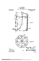
- Figure 1 is a pers cctive view 0 the washer with parts assemb ed for operation.
- Fig. 2 is a vertical section.
- Fig. 3 is a topplan view with the covers removed.
- Fig. 4 is a detail top plan view of the dish rack.
- my washer consists of a main or exterior tub or tank 1; a removable inner receptacle or carrier 2 ;and a. dish rackB, adapted to be' removabl arranged in the-innenreceptacle. 35
- the tu or tank 1 is open at the top and is provided with a removable cover 10, fornormally closing the same-at the top.
- This tube isjprovided with a pain operative from -n the rack 3.
- a. vertical pump barrel or cylinder 4 vertically arranged at the exterior of and fixed to the tub and provided with a reciprocatin piston operated by handle 40, the upper end removable cap 41.
- the lower end of tlie barrel communicates with the bottom portion of the interior of the tub throu h suction duct or opening 42, provided wit any usual or.
- the pump barre in the exampleillustrated, is shown provided with discharge pipes i4, and 47, extending to and terminatthe exterior of the washer or sprayifg the.
- the pipe 44 is made inzscctions, one section fixed to tank 1,:1nd anlpther section fixed to cover '10, the said sections being connected together through slip joint 4:6, to permit removal and application of the cover 10, and the section of ipe -14, carried thereby.
- An upwar 1y directed sprayer head 4-8 is arranged centrally within the lower portion of the inner receptacle to direct the water upwardly against the dishes on the rack, and this head 48 is carried by a discharge pipe 47, extending from through the wall of the outer tank.
- The. sprayer heads 45, 48 are of any suitable construction and are usually made removable.
- the inner receptacle is open at the to and provided with suitable hand holds an with perforated bottom 21.
- the bottom and side wall of the inner receptacle are suitably slotted, see 22, to receive the dis: charge pipe, and sprayer head 48,- and permit insertion and removal of said recepthe lower end of the pump and passing tacle into and from the tank -1,without in-'.
- the dish rack is prefer-a ly removably arranged within the inner receptacle. -In.
- the rack can-be formed by a series of spaced vertical wires 30, converging upwardly and secured f to-' gether at their upper ends a ⁇ : 31, undo. series of spaced encircling horlzontal wires.
- the dishes are arranged on the rack and then placed in the inner receptacle ,which is then placed in the tub.
- the 1% quired amount of hot water is then pmired .in'the tub which is then closed by the cover
- The'pump piston is thenreeiprocated and the water is' drawn into the pump and fer-ciblydischarged against the dishes through the spray head.
- a tub V provided with, a remm'abie cover, an exterior pump having its barre fixeci to said tuh'and provided with a sucticm inlet uponing into said tub above the floor the-reef, a spray nozzle carried by said cover and 11m meme pending ti'zei'efrom enir'aily into Shiti tub,
Landscapes
- Containers And Packaging Bodies Having A Special Means To Remove Contents (AREA)
Description
M. J WEA ER.
msn WASHER APPLIUATIOF FILED SEPT. 22, 1909.
Patented July 5,1910.
2 SHEETS-SHEET 1.
anmwtoz .M. L WEAVER.
DISH WASHER.
AIPLIUATIOH FILED 8162122, 1009.
Patented July 5,1910.
2 SHEETS-SHEET 2.
m m m suitable e dishes arranged within the washer .of the pump barrel being closed b UNITED sTATEs PATENT OFFICE.
MARY, JANE WEAVER, or nosnnun, TEXAS.
msmwasnnn.
Specification of Letters Patent. Patented J uly 5, 1910.
Application filed September 22, 1909. Serial No. 518,948.
T 0 all whom. it may concern:
Be it known that I, MARY J ANE WEAVER, a citizen of the United States, residing at Rosebud, Falls county, Texas, have invented certain new and useful Improvements in Dish-\Vashers; and I do hereby declare the following to be a full, clear, and exact description of the invention, such as will enable others skilled in the art to 'lllClLlt appertains to make and use the same.
This invention relates to certain improvements in dish washers; and the objects and nature of my invention will be readily understood by those skilled in the art in the featuresin construction and'in combinations as more fully and particularly set forth hereinafter.
Referring to the accompanying drawings Figure 1, is a pers cctive view 0 the washer with parts assemb ed for operation. Fig. 2, is a vertical section. Fig. 3, is a topplan view with the covers removed. Fig. 4, is a detail top plan view of the dish rack.
In the specific example illustrated, my washer consists of a main or exterior tub or tank 1; a removable inner receptacle or carrier 2 ;and a. dish rackB, adapted to be' removabl arranged in the-innenreceptacle. 35
The tu or tank 1, is open at the top and is provided with a removable cover 10, fornormally closing the same-at the top. This tube isjprovided with a pain operative from -n the rack 3. In the example illustrated, show a. vertical pump barrel or cylinder 4, vertically arranged at the exterior of and fixed to the tub and provided with a reciprocatin piston operated by handle 40, the upper end removable cap 41. The lower end of tlie barrel communicates with the bottom portion of the interior of the tub throu h suction duct or opening 42, provided wit any usual or.
166k valve'43 opening inw with respect to the pump barrel.
The pump barre, in the exampleillustrated, is shown provided with discharge pipes i4, and 47, extending to and terminatthe exterior of the washer or sprayifg the.
ing in sprayer heads 45., 48,:irri1n edwitliin the inner receptacles to spr'a t e Water forcibly against the surfaces 0 the dishes carried bythe dish rack. The pipe 44, ex-
tends from the lower end of the pump barrel upwardly along theexterior-of the outer tank and extends through the cover 10 and depends therefrom within the inner receptacle and carries the sprayer head if), above the dish rack and is arranged to spray the water down on the dishes carried by the rack. The pipe 44, is made inzscctions, one section fixed to tank 1,:1nd anlpther section fixed to cover '10, the said sections being connected together through slip joint 4:6, to permit removal and application of the cover 10, and the section of ipe -14, carried thereby. An upwar 1y directed sprayer head 4-8, is arranged centrally within the lower portion of the inner receptacle to direct the water upwardly against the dishes on the rack, and this head 48 is carried by a discharge pipe 47, extending from through the wall of the outer tank. The. sprayer heads 45, 48, are of any suitable construction and are usually made removable.
The inner receptacle is open at the to and provided with suitable hand holds an with perforated bottom 21. The bottom and side wall of the inner receptacle are suitably slotted, see 22, to receive the dis: charge pipe, and sprayer head 48,- and permit insertion and removal of said recepthe lower end of the pump and passing tacle into and from the tank -1,without in-'.
terference with or from said pipe and'head. The dish rack is prefer-a ly removably arranged within the inner receptacle. -In.
the specific example illustratedpits lower,
end rests on the bottom of the inner receptacle and tapers upwardly and centrally therein and consists of an open frame,
formed with exterior sockets or ledges to support the'dishes on the exterior of and around the open frame. The rack can-be formed by a series of spaced vertical wires 30, converging upwardly and secured f to-' gether at their upper ends a}: 31, undo. series of spaced encircling horlzontal wires.
32,,secured to each of the vertical wires and, at the intervals between the. yertical wires ios looped or offset outwardly to form". dish?" holding brackets or sockets 33. The
can be arranged vertically or on overlapping about the exterior of the rack, each at its lower edge resting on a braeket 0i" socket 83, aboilt as shown. 7
i In practicethe dishes are arranged on the rack and then placed in the inner receptacle ,which is then placed in the tub. The 1% quired amount of hot water is then pmired .in'the tub which is then closed by the cover The'pump piston is thenreeiprocated and the water is' drawn into the pump and fer-ciblydischarged against the dishes through the spray head.
i What I claim' is: i
In combination, in a dish washer, a tub V provided with, a remm'abie cover, an exterior pump having its barre fixeci to said tuh'and provided with a sucticm inlet uponing into said tub above the floor the-reef, a spray nozzle carried by said cover and 11m meme pending ti'zei'efrom enir'aily into Shiti tub,
in series aroundpsairi lower central nozzle and below saiii upper nozzle, substantially as described. v,
In testimony wherein. I affix my si'tnahire in PXTH'DPQ 0i" twu witness-vs.
MARY "if: NE \VEAVEH,
Witnesses: v
E. 4. PARKER,
Priority Applications (1)
| Application Number | Priority Date | Filing Date | Title |
|---|---|---|---|
| US51894309A US963672A (en) | 1909-09-22 | 1909-09-22 | Dish-washer. |
Applications Claiming Priority (1)
| Application Number | Priority Date | Filing Date | Title |
|---|---|---|---|
| US51894309A US963672A (en) | 1909-09-22 | 1909-09-22 | Dish-washer. |
Publications (1)
| Publication Number | Publication Date |
|---|---|
| US963672A true US963672A (en) | 1910-07-05 |
Family
ID=3032070
Family Applications (1)
| Application Number | Title | Priority Date | Filing Date |
|---|---|---|---|
| US51894309A Expired - Lifetime US963672A (en) | 1909-09-22 | 1909-09-22 | Dish-washer. |
Country Status (1)
| Country | Link |
|---|---|
| US (1) | US963672A (en) |
-
1909
- 1909-09-22 US US51894309A patent/US963672A/en not_active Expired - Lifetime
Similar Documents
| Publication | Publication Date | Title |
|---|---|---|
| US1661602A (en) | Milk-can-washing machine | |
| NO118407B (en) | ||
| US910882A (en) | Bottle-washing apparatus. | |
| US998742A (en) | Repository. | |
| US1532809A (en) | Dishwasher nozzle | |
| US2065466A (en) | Apparatus for washing milk cans and the like | |
| US1624865A (en) | Tank-car-cleaning device | |
| US1206206A (en) | Dish-washing machine. | |
| US1988000A (en) | Detergent dispenser | |
| US1752823A (en) | Spray nozzle | |
| CN206083261U (en) | Belt cleaning device of spare part in fluorine coating production | |
| US1345519A (en) | Casing for dish-washing machines | |
| CN106742865A (en) | A kind of industrial chemicals storage tank easy to clean | |
| US2517394A (en) | Apparatus for conditioning containers and the like | |
| US1681839A (en) | Dish washing, sterilizing, and drying machine | |
| DE69302373D1 (en) | DISHWASHER WITH VALVE DEVICE FOR SEPARATING GRANULES FROM THE WASHING HOSE | |
| US1429069A (en) | Dishwasher | |
| US670234A (en) | Soap-holder and sprayer. | |
| US1900529A (en) | Dishwasher | |
| US424102A (en) | William t | |
| US1193495A (en) | Dish washing | |
| US988899A (en) | Apparatus for cleaning beer-pipes. | |
| US870384A (en) | Beer-pipe cleaner. | |
| US661602A (en) | Filter. | |
| US1938558A (en) | Sterilizer |