US962539A - Folding umbrella. - Google Patents
Folding umbrella. Download PDFInfo
- Publication number
- US962539A US962539A US50928909A US1909509289A US962539A US 962539 A US962539 A US 962539A US 50928909 A US50928909 A US 50928909A US 1909509289 A US1909509289 A US 1909509289A US 962539 A US962539 A US 962539A
- Authority
- US
- United States
- Prior art keywords
- sections
- umbrella
- ribs
- section
- staff
- Prior art date
- Legal status (The legal status is an assumption and is not a legal conclusion. Google has not performed a legal analysis and makes no representation as to the accuracy of the status listed.)
- Expired - Lifetime
Links
Images
Classifications
-
- A—HUMAN NECESSITIES
- A45—HAND OR TRAVELLING ARTICLES
- A45B—WALKING STICKS; UMBRELLAS; LADIES' OR LIKE FANS
- A45B19/00—Special folding or telescoping of umbrellas
- A45B19/10—Special folding or telescoping of umbrellas with collapsible ribs
Definitions
- the invention aims primarily to provide a device of this class of simple character and embodying but few parts.
- One'of the novel features of the invention resides in the means provided for locking in an extended and unfolded relation the sections of the foldable ribs of the umbrella frame, the means being of such a character as not to bulge the cover of the umbrella when the umbrella is raised or opened.
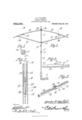
- FIG. 1 is a view in elevation, the parts being broken away of the umbrella frame comprising the invention, the same being shown open.
- FIG. 2 is a similar view but showing the umbrella folded.
- Fig. 3 is a detail perspective view of the middle portion of one of the ribs of the umbrella frame.
- Fig. 4 is a vertical longitudinal sectional view through one of the ribs at the middle portion thereof.
- Fig. 5 is a transverse sectional view through the rib.
- the umbrella staff is illustrated as comprised of an upper section indicated by the numeral 5 and lower section indicated by the numeral 6, the said lower section being provided at its lower end with a handle 7.
- the two sections 5 and 6 are detachably connected by forming in the lower end of the section 5 a threaded bore which is indicated by the numeral 8 and forming at the upper end of the lower section 6 a threaded stud or tang 9 which is to be threaded into the bore 8 for the purpose stated.
- the usual fixed head 10 to which the ribs are to be pivoted as will be presently explained.
- Slidable upon the two sections comprising the staff is the usual form of runner indicated by the numeral 11, the stay ribs being pivoted to this runner and the runner being held against sliding upon the staff when the umbrella is opened through the medium of the usual spring catch 12.
- Each of the umbrella ribs comprises an upper or inner section 13 and lower or outer section 14, the two sections being pivotally connected as at 15 and having, preferably, a rectangular cross section as clearly illus trated in Fig. 3 of the drawings.
- the two sections 13 and 14 of each rib are shouldered as at 16 at their pivot ends so when they are in unfolded relation as, for example, when the umbrella is open and in use these shoul ders will abut and will hold the sections in proper alinement, or rather will prevent them swinging upon their pivot beyond the alined position and will hold these two sections of each rib in an alined position, or, more specifically speaking, against folding up.
- the sections 13 and 14 are channeled in their lower or inner faces either throughout their lengths or solely adjacent their point of connection. These channels have been indicated at 18.
- a wedge-shaped slide 19 is mounted within the channels and is designed to be moved into position between the pivot pin 15 and the inner walls of the channels so as to lock the two rib sections against independent movement.
- a stop projection 20 is arranged upon the slide and is designed to limit the movement thereof by coming into contact with the pin 15. Obviously, by shifting the slide in one direction the sections 13 and 14 can be folded together while, by moving it in the other direction said sections will be held firmly in alinement.
- the latch slides 19 are moved to position to hold the rib sections in alinement and the umbrella may then be used in the same manner as the ordinary umbrella.
- the latch slides 19 are moved from under pivots 15 so as to rest only upon the sections 13 of the ribs, and the sections 14 of the ribs are then folded in on the sections 13, the sections 13 being swung upwardly upon the pivot wire which connects them at their inner ends to the head 10, said ribs 21 are pivoted at their outer ends to a runner to each of the outer sections 14 and at their inner ends to a runner which performs the same function as the said ribs of the ordinary umbrella.
- a head 22 is formed upon the staff 8 adspace between the two heads to permit the thimble to which the cover is fastened to have a slight play and thus relieve the cover I of strain While the umbrella is being folded or being extended.
- each rib comprising channeled sections, a pivot pin connecting the sections and extending transversely across the channels of the sections and spaced from the bottoms thereof, the bottom of the channel of one section being inclined whereby the said channel of the said section is decreased in depth in a direction from the pivoted end of the section, a slide arranged in the channel of the sections and at one end tapered to wedge shape to a degree corresponding substantially to the inclination of the bottom wall of the said channel, the said slide lying between the bottoms of the channels and the said pivot pin and being adapted to wedge between the said channel bottoms and the said pin when slid in the direction of decrease in depth of the last said channel, and an abutment upon the slide adapted to engage with the pivot pin when the slide is so wedged.
Landscapes
- Walking Sticks, Umbrellas, And Fans (AREA)
Description
0. E. WALTON.
FOLDING UMBRELLA.
APPLICATION FILED JULY 24,1909.
962,539. Patented June 28, 1910.
Witwaoozo ORBIN E. WALTON, OF WEST UNION, WEST VIRGINIA, ASSIGNOR 0F ONE-HALF TO U. GRANT SUMMERS, OF WEST UNION, WEST VIRGINIA.
FOLDING UMBRELLA.
Specification of Letters Patent.
Application filed July 24, 1909.
To all whom it may concern:
Be it known that I, ORRIN E. WALTON, a citizen of the United States, residing at l/Vest Union, in the county of Doddridge and State of West Virginia, have invented a new and useful Folding Umbrella, of which the following is a specification.
It is the object of the present invention to provide an improved construction of folding umbrellas.
The invention aims primarily to provide a device of this class of simple character and embodying but few parts.
One'of the novel features of the invention resides in the means provided for locking in an extended and unfolded relation the sections of the foldable ribs of the umbrella frame, the means being of such a character as not to bulge the cover of the umbrella when the umbrella is raised or opened.
In the accompanying drawings :-Figure 1 is a view in elevation, the parts being broken away of the umbrella frame comprising the invention, the same being shown open. Fig. 2 is a similar view but showing the umbrella folded. Fig. 3 is a detail perspective view of the middle portion of one of the ribs of the umbrella frame. Fig. 4 is a vertical longitudinal sectional view through one of the ribs at the middle portion thereof. Fig. 5 is a transverse sectional view through the rib.
In the drawings, the umbrella staff is illustrated as comprised of an upper section indicated by the numeral 5 and lower section indicated by the numeral 6, the said lower section being provided at its lower end with a handle 7. The two sections 5 and 6 are detachably connected by forming in the lower end of the section 5 a threaded bore which is indicated by the numeral 8 and forming at the upper end of the lower section 6 a threaded stud or tang 9 which is to be threaded into the bore 8 for the purpose stated.
Upon the upper section 5 of the umbrella staff adjacent the upper end thereof there is provided the usual fixed head 10 to which the ribs are to be pivoted as will be presently explained. Slidable upon the two sections comprising the staff is the usual form of runner indicated by the numeral 11, the stay ribs being pivoted to this runner and the runner being held against sliding upon the staff when the umbrella is opened through the medium of the usual spring catch 12.
Each of the umbrella ribs comprises an upper or inner section 13 and lower or outer section 14, the two sections being pivotally connected as at 15 and having, preferably, a rectangular cross section as clearly illus trated in Fig. 3 of the drawings. The two sections 13 and 14 of each rib are shouldered as at 16 at their pivot ends so when they are in unfolded relation as, for example, when the umbrella is open and in use these shoul ders will abut and will hold the sections in proper alinement, or rather will prevent them swinging upon their pivot beyond the alined position and will hold these two sections of each rib in an alined position, or, more specifically speaking, against folding up. The sections 13 and 14 are channeled in their lower or inner faces either throughout their lengths or solely adjacent their point of connection. These channels have been indicated at 18. A wedge-shaped slide 19 is mounted within the channels and is designed to be moved into position between the pivot pin 15 and the inner walls of the channels so as to lock the two rib sections against independent movement. A stop projection 20 is arranged upon the slide and is designed to limit the movement thereof by coming into contact with the pin 15. Obviously, by shifting the slide in one direction the sections 13 and 14 can be folded together while, by moving it in the other direction said sections will be held firmly in alinement.
When the umbrella is for ordinary use the latch slides 19 are moved to position to hold the rib sections in alinement and the umbrella may then be used in the same manner as the ordinary umbrella. When it is desired to fold the umbrella its staff sections are separated, the latch slides 19 are moved from under pivots 15 so as to rest only upon the sections 13 of the ribs, and the sections 14 of the ribs are then folded in on the sections 13, the sections 13 being swung upwardly upon the pivot wire which connects them at their inner ends to the head 10, said ribs 21 are pivoted at their outer ends to a runner to each of the outer sections 14 and at their inner ends to a runner which performs the same function as the said ribs of the ordinary umbrella.
' jacent the head 10, there being sufficient,
I A head 22 is formed upon the staff 8 adspace between the two heads to permit the thimble to which the cover is fastened to have a slight play and thus relieve the cover I of strain While the umbrella is being folded or being extended.
Having thus fully described my invention, what I claim as new and desire to secure by Letters-Patent is In an umbrella, a staff, ribs pivotally connected to the stafi", each rib comprising channeled sections, a pivot pin connecting the sections and extending transversely across the channels of the sections and spaced from the bottoms thereof, the bottom of the channel of one section being inclined whereby the said channel of the said section is decreased in depth in a direction from the pivoted end of the section, a slide arranged in the channel of the sections and at one end tapered to wedge shape to a degree corresponding substantially to the inclination of the bottom wall of the said channel, the said slide lying between the bottoms of the channels and the said pivot pin and being adapted to wedge between the said channel bottoms and the said pin when slid in the direction of decrease in depth of the last said channel, and an abutment upon the slide adapted to engage with the pivot pin when the slide is so wedged.
In testimony that I claim the foregoing as my own, I have hereto aflixed my signature in the presence of two witnesses.
ORRIN ,E. IVALTON.
Witnesses J. O. WILCOX, J. P. SUMMERS.
Priority Applications (1)
| Application Number | Priority Date | Filing Date | Title |
|---|---|---|---|
| US50928909A US962539A (en) | 1909-07-24 | 1909-07-24 | Folding umbrella. |
Applications Claiming Priority (1)
| Application Number | Priority Date | Filing Date | Title |
|---|---|---|---|
| US50928909A US962539A (en) | 1909-07-24 | 1909-07-24 | Folding umbrella. |
Publications (1)
| Publication Number | Publication Date |
|---|---|
| US962539A true US962539A (en) | 1910-06-28 |
Family
ID=3030937
Family Applications (1)
| Application Number | Title | Priority Date | Filing Date |
|---|---|---|---|
| US50928909A Expired - Lifetime US962539A (en) | 1909-07-24 | 1909-07-24 | Folding umbrella. |
Country Status (1)
| Country | Link |
|---|---|
| US (1) | US962539A (en) |
Cited By (1)
| Publication number | Priority date | Publication date | Assignee | Title |
|---|---|---|---|---|
| US20240008608A1 (en) * | 2022-07-08 | 2024-01-11 | Phaeton Manufacturing Llc | Foldable Rod of an Umbrella |
-
1909
- 1909-07-24 US US50928909A patent/US962539A/en not_active Expired - Lifetime
Cited By (2)
| Publication number | Priority date | Publication date | Assignee | Title |
|---|---|---|---|---|
| US20240008608A1 (en) * | 2022-07-08 | 2024-01-11 | Phaeton Manufacturing Llc | Foldable Rod of an Umbrella |
| US12396532B2 (en) * | 2022-07-08 | 2025-08-26 | Phaeton Manufacturing Llc | Foldable rod of an umbrella |
Similar Documents
| Publication | Publication Date | Title |
|---|---|---|
| US440568A (en) | Folding landing-net | |
| US1444569A (en) | Legged article | |
| US1519892A (en) | Collapsible shovel | |
| US790653A (en) | Door-securer. | |
| US1979567A (en) | Folding rule | |
| US1396372A (en) | Collapsible cane | |
| US781609A (en) | Folding hammock-stand. | |
| US1397794A (en) | Umbrella | |
| US744476A (en) | Folding umbrella. | |
| US766059A (en) | Knife. | |
| US606099A (en) | Folding umbrella | |
| US729291A (en) | Tripod. | |
| US1490924A (en) | Folding umbrella | |
| US1045358A (en) | Folding umbrella. | |
| US855142A (en) | Folding umbrella. | |
| US1083050A (en) | Folding umbrella. | |
| US1217709A (en) | Foldable umbrella. | |
| US963003A (en) | Folding umbrella. | |
| US507588A (en) | Folding umbrella | |
| US1149828A (en) | Folding umbrella. | |
| US965652A (en) | Umbrella or parasol. | |
| US1049743A (en) | Folding umbrella. | |
| US987236A (en) | Folding table. | |
| US1263891A (en) | Folding umbrella. | |
| US934506A (en) | Folding umbrella. |