US9615046B2 - Image conversion apparatus and method reducing number of pixel counts processing - Google Patents
Image conversion apparatus and method reducing number of pixel counts processing Download PDFInfo
- Publication number
- US9615046B2 US9615046B2 US14/619,868 US201514619868A US9615046B2 US 9615046 B2 US9615046 B2 US 9615046B2 US 201514619868 A US201514619868 A US 201514619868A US 9615046 B2 US9615046 B2 US 9615046B2
- Authority
- US
- United States
- Prior art keywords
- pixel
- value
- image
- image conversion
- row
- Prior art date
- Legal status (The legal status is an assumption and is not a legal conclusion. Google has not performed a legal analysis and makes no representation as to the accuracy of the status listed.)
- Expired - Fee Related, expires
Links
- 238000006243 chemical reaction Methods 0.000 title claims abstract description 375
- 238000000034 method Methods 0.000 title claims description 263
- 239000000284 extract Substances 0.000 claims abstract description 9
- 230000008569 process Effects 0.000 claims description 207
- 238000009792 diffusion process Methods 0.000 abstract description 75
- 230000003287 optical effect Effects 0.000 description 91
- 238000010586 diagram Methods 0.000 description 33
- 238000004364 calculation method Methods 0.000 description 27
- 230000000875 corresponding effect Effects 0.000 description 16
- 230000000694 effects Effects 0.000 description 13
- 238000003491 array Methods 0.000 description 5
- 230000002596 correlated effect Effects 0.000 description 5
- 230000006870 function Effects 0.000 description 5
- 230000001174 ascending effect Effects 0.000 description 2
- 230000004075 alteration Effects 0.000 description 1
- 230000008859 change Effects 0.000 description 1
- 238000004891 communication Methods 0.000 description 1
- 239000002131 composite material Substances 0.000 description 1
- 238000007796 conventional method Methods 0.000 description 1
- 239000004973 liquid crystal related substance Substances 0.000 description 1
- 239000004335 litholrubine BK Substances 0.000 description 1
- 230000008520 organization Effects 0.000 description 1
- 230000009467 reduction Effects 0.000 description 1
- 238000006467 substitution reaction Methods 0.000 description 1
- 230000000007 visual effect Effects 0.000 description 1
Images


Classifications
-
- G—PHYSICS
- G06—COMPUTING; CALCULATING OR COUNTING
- G06T—IMAGE DATA PROCESSING OR GENERATION, IN GENERAL
- G06T5/00—Image enhancement or restoration
- G06T5/70—Denoising; Smoothing
-
- H04N5/378—
-
- H—ELECTRICITY
- H04—ELECTRIC COMMUNICATION TECHNIQUE
- H04N—PICTORIAL COMMUNICATION, e.g. TELEVISION
- H04N25/00—Circuitry of solid-state image sensors [SSIS]; Control thereof
- H04N25/70—SSIS architectures; Circuits associated therewith
- H04N25/71—Charge-coupled device [CCD] sensors; Charge-transfer registers specially adapted for CCD sensors
- H04N25/75—Circuitry for providing, modifying or processing image signals from the pixel array
-
- G—PHYSICS
- G06—COMPUTING; CALCULATING OR COUNTING
- G06T—IMAGE DATA PROCESSING OR GENERATION, IN GENERAL
- G06T11/00—2D [Two Dimensional] image generation
- G06T11/60—Editing figures and text; Combining figures or text
-
- G06T5/002—
-
- H—ELECTRICITY
- H04—ELECTRIC COMMUNICATION TECHNIQUE
- H04N—PICTORIAL COMMUNICATION, e.g. TELEVISION
- H04N1/00—Scanning, transmission or reproduction of documents or the like, e.g. facsimile transmission; Details thereof
- H04N1/40—Picture signal circuits
- H04N1/409—Edge or detail enhancement; Noise or error suppression
- H04N1/4092—Edge or detail enhancement
Definitions
- the embodiment discussed herein is related to an image conversion program, a recording medium, an image conversion apparatus, and an image conversion method.
- Techniques of converting an image into an image given a blurring effect has existed. For example, in one technique, to execute a process of giving a blurring effect, a blurring range is calculated for each pixel to be processed in an input image. In another technique, a filter process is executed by using multiple moving average filters of different sizes to generate multiple blurred images, and weight is given to mutually corresponding pixels of the multiple blurred image data for each of the blurred images to use an average value of the blurred image data for a composite blurred image.
- an exposure amount is obtained by a calculation from an RGB value of each pixel of an input image to execute a process of giving a blurring effect to the exposure amount of each pixel, and the exposure amount of each pixel given the blurring effect is restored to an RGB value (see, e.g., Japanese Laid-Open Patent Publication Nos. H6-036022; 2004-133551; and 2001-216513).
- the conventional techniques described above is problematic in that the amount of calculation involved in the process of giving a blurring effect to an image becomes large and results in an increase in the processing time consumed for a process of converting an image.
- the process of giving a blurring effect is a process of distributing values of pixels according to an aperture shape defined as a blurring range for each pixel in an image, leading to a large calculation amount.
- a non-transitory, computer-readable recording medium stores therein an image conversion program that causes a computer to execute a process that includes extracting, among pixel rows parallel to an object pixel row in an image to be converted, a first pixel row overlapping a region formed of a pixel group within a predetermined range from an given pixel of the object pixel row and a second pixel row having a number of pixels successively overlapping the region equal to or greater than that of the first pixel row; acquiring a pixel count from a pixel at an end in a given direction that is any one among a scanning direction of the object pixel row and a direction opposite to the scanning direction, in a first pixel group included in the region in the extracted first pixel row, to a first pixel included in the first pixel group; identifying a second pixel at a position advanced by the acquired pixel count in a direction opposite to the given direction from the pixel at the end in the given direction in a second pixel group included in the region
- FIG. 1A is an explanatory diagram (part 1) of an operation example of an image conversion apparatus according to an embodiment
- FIG. 1B is an explanatory diagram (part 2) of an operation example of the image conversion apparatus according to the embodiment
- FIG. 2 is a block diagram of an example of a hardware configuration of the image conversion apparatus
- FIG. 3 is a block diagram of an example of a functional configuration of the image conversion apparatus
- FIG. 4 is an explanatory diagram of a first example of an aperture shape and a first example of storage contents of an aperture shape table
- FIG. 5 is an explanatory diagram (part 1) of an operation example of an image conversion process
- FIGS. 6A, 6B, and 6C are explanatory diagrams (part 2) of the operation example of the image conversion process
- FIG. 7 is an explanatory diagram (part 3) of the operation example of the image conversion process
- FIG. 8 is a flowchart of an example of an image conversion process procedure in a case of scanning in an x-axis direction
- FIG. 9 is a flowchart of an example of an initialization process procedure in the case of scanning in the x-axis direction;
- FIG. 10 is a flowchart of an example of an optical energy value conversion process procedure in the case of scanning in the x-axis direction;
- FIG. 11 is a flowchart (part 1) of an example of an optical diffusion process procedure in the case of scanning in the x-axis direction;
- FIG. 12 is a flowchart (part 2) of the example of the optical diffusion process procedure in the case of scanning in the x-axis direction;
- FIG. 13 is a flowchart of an example of an RGB value conversion process procedure
- FIGS. 14A and 14B are explanatory diagrams of an operation example of the image conversion process without using the aperture shape table
- FIG. 15 is a flowchart (part 1) of an example of an optical diffusion process procedure without using the aperture shape table;
- FIG. 16 is a flowchart (part 2) of the example of the optical diffusion process procedure without using the aperture shape table;
- FIG. 17 is an explanatory diagram of a second example of an aperture shape and a second example of storage contents of the aperture shape table
- FIG. 18 is a flowchart of an example of the initialization process procedure in a case of scanning in a y-axis direction;
- FIG. 19 is a flowchart of an example of the optical energy value conversion process procedure in the case of scanning in the y-axis direction;
- FIG. 20 is a flowchart (part 1) of an example of the optical diffusion process procedure in the case of scanning in the y-axis direction;
- FIG. 21 is a flowchart (part 2) of the example of the optical diffusion process procedure in the case of scanning in the y-axis direction;
- FIG. 27 is a flowchart of an example of a P-acquisition process procedure
- FIG. 28 is a flowchart of an example of an X/Y-acquisition process procedure
- FIG. 29 is a flowchart of an example of a Ro-acquisition process procedure
- FIG. 30 is an explanatory diagram of a third example of an aperture shape and a third example of storage contents of the aperture shape table
- FIG. 31 is an explanatory diagram of a fourth example of an aperture shape and a fourth example of storage contents of the aperture shape table;
- FIG. 32 is a flowchart (part 1) of an example of a procedure of the process of conversion from an optical energy value to an RGB value;
- FIG. 33 is a flowchart (part 2) of an example of a procedure of the process of conversion from an optical energy value to an RGB value;
- FIG. 34 is an explanatory diagram (part 1) of an example of a result of the image conversion process of the embodiment
- FIG. 35 is an explanatory diagram (part 2) of an example of a result of the image conversion process of the embodiment.
- FIG. 36 is an explanatory diagram of comparison of the speed between an image conversion process on the basis of a pixel and the image conversion process of the embodiment.
- FIG. 1A is an explanatory diagram (part 1) of an operation example of the image conversion apparatus according to the present embodiment.
- An image conversion apparatus 100 is a computer receives an original image and executes a process of giving a blurring effect to the original image to convert the original image into a blurred image.
- the image conversion apparatus 100 is a portable terminal such as a smartphone and a mobile telephone.
- the image conversion apparatus 100 displays popup dialogue. In this case, by blurring the background, exclusive of the popup dialogue, by a blurring effect, the image conversion apparatus 100 can provide a visual effect that draws the attention of the user to the popup dialogue.
- a process of giving the blurring effect is proportional to a product of the number of pixels in an image and the number of pixels included in an aperture shape, resulting in a large processing amount, and therefore, takes time.
- the image conversion apparatus 100 according to the present embodiment reduces the processing amount of the process of giving the blurring effect to shorten the processing time.
- a process of converting an original image into a blurred image having a blurring effect will be referred to as an “image conversion process”. Sizes of the original and blurred images are defined by a vertical width H [in pixels] and a horizontal width W [in pixels]. Reference characters of the original and blurred images are defined as IN and OUT, respectively.
- the original and blurred images are on two-dimensional orthogonal coordinates with a horizontal axis and a vertical axis defined as an x-axis and a y-axis, respectively.
- the aperture shape 101 is an aperture shape specified in advance by a user.
- the specified aperture shape 101 is a shape of a region formed of a pixel group within a predetermined range from a diffusion source pixel.
- the value of the pixel may be an RGB value or an optical energy value indicative of an exposure amount converted from the RGB value.
- the optical energy value is a value obtained by multiplying illuminance by time.
- the image conversion apparatus 100 according to the present embodiment achieves a reduction in calculation amount of a blurring process.
- (B1) to (B3) of FIG. 1A depict which pixel affects pixels overlapping with a blurring shape.
- the scanning direction may be an x-axis direction, a y-axis direction, or a diagonal direction different from the x-axis direction and the y-axis direction.
- the number of pixels of the first pixel row overlapping the aperture shape 101 is 3 [pixels] while the number of pixels of the second pixel row overlapping the aperture shape 101 is 5 [pixels].
- the number of pixels overlapping the aperture shape 101 in a pixel row in the scanning direction will hereinafter be referred to as a “blur amount”.
- the pixels are at the same relative positions in the region overlapping the aperture shape.
- IN[7][5] is located at 0th position counted in the direction opposite to the scanning direction.
- IN[4][4] is located at 0th position counted in the direction opposite to the scanning direction.
- the relative positions in the region may be viewed in the scanning direction. Since both the first pixel and the second pixel are included in the aperture shape 101 , the first pixel and the second pixel are affected by the diffusion source pixel IN[5][6].
- (B3) of FIG. 1A if the diffusion source pixel of the object pixel row is set to IN[5][2], the second pixel is included in the aperture shape 101 and therefore, the second pixel is affected by the diffusion source pixel IN[5][2]. However, the first pixel is not included in the aperture shape 101 and therefore, the first pixel is not affected by the diffusion source pixel IN[5][2]. Although not depicted, if the diffusion source pixel of the object pixel row is set to IN[5][3], the second pixel is included in the aperture shape 101 and therefore, the second pixel is affected by the diffusion source pixel IN[5][3]. However, the first pixel is not included in the aperture shape 101 and therefore, the first pixel is not affected by the diffusion source pixel IN[5][3].
- the first pixel is affected by the diffusion source pixels IN[5][4] to IN[5][6].
- the second pixel is affected by the diffusion source pixels IN[5][2] to IN[5][6]. Therefore, a portion of the affecting pixels is common to the first and second pixels and thus, the calculation result can be reused.
- the number of affected pixels coincides with the blur amount. The reuse of the calculation result will be described with reference to FIG. 1B .
- FIG. 1B is an explanatory diagram (part 2) of an operation example of the image conversion apparatus according to the present embodiment.
- the image conversion apparatus 100 refers to a storage unit that stores a value of the first pixel in the case of converting the original image IN and calculates a value of the second pixel in the case of converting the original image IN.
- the image conversion apparatus 100 defines an average of a value of the first pixel in the case of converting the original image IN, a value of the diffusion source pixel IN[5][2], and a value of the diffusion source pixel IN[5][3], as a value of the second pixel in the case of converting the original image IN.
- the image conversion apparatus 100 executes four addition processes for adding the diffusion source pixels IN[5][2] to IN[5][6].
- the image conversion apparatus 100 only needs to execute two addition processes. The operation of the image conversion apparatus 100 will hereinafter be described in detail with reference to FIGS. 2 to 36 .
- FIG. 2 is a block diagram of an example of a hardware configuration of the image conversion apparatus.
- the image conversion apparatus 100 is assumed to be a portable terminal such as a smartphone and has a CPU 201 , read only memory (ROM) 202 , random access memory (RAM) 203 , flash ROM 204 , a flash ROM controller 205 , and flash ROM 206 .
- the image conversion apparatus 100 also has a display 207 , an I/F 208 , and a touch panel 209 .
- the units are connected to each other by a bus 210 .
- the CPU 201 is a control apparatus responsible for general control of the image conversion apparatus 100 .
- the ROM 202 is nonvolatile memory that stores programs such as a boot program.
- the RAM 203 is volatile memory used as a work area of the CPU 201 .
- the flash ROM 204 is rewritable nonvolatile memory and is, for example, NOR flash memory with a high read-out speed.
- the flash ROM 204 stores system software such as an operating system (OS) and application software. For example, when the OS is updated, the image conversion apparatus 100 receives a new OS through the I/F 208 and updates the old OS stored in the flash ROM 204 to the received new OS.
- An image conversion program according to the present embodiment may be present in the flash ROM 204 as a system call that is called by the OS.
- the flash ROM controller 205 is a control apparatus that controls the reading and writing of data with respect to the flash ROM 206 , under the control of the CPU 201 .
- the flash ROM 206 is a rewritable nonvolatile memory and is NAND flash memory for the main purpose of storage and transportation of data, for example.
- the flash ROM 206 stores data written thereto under the control of the flash ROM controller 205 .
- Specific examples of data are image data and video data obtained through the I/F 208 by a user using the image conversion apparatus 100 , and the image conversion program according to the present embodiment may be stored.
- a memory card or an SD card can be employed as the flash ROM 206 .
- the display 207 displays a cursor, icons, and/or tool boxes as well as data such as documents, images, and functional information.
- a TFT liquid crystal display can be employed as the display 207 .
- the I/F 208 is connected through a communication line to a network 211 such as a local area network (LAN), a wide area network (WAN), and the Internet, and is connected via the network 211 to another apparatus.
- the I/F 208 is responsible for an internal interface with the network 211 and controls the input and output of data with respect to an external apparatus.
- a modem or a LAN adapter can be employed as the I/F 208 .
- the touch panel 209 is an apparatus that inputs data through contact by a user.
- FIG. 3 is a block diagram of an example of a functional configuration of the image conversion apparatus.
- the image conversion apparatus 100 includes a selecting unit 301 , an object pixel row acquiring unit 302 , an extracting unit 303 , a pixel count acquiring unit 304 , a second-pixel identifying unit 305 , a diffusion source pixel identifying unit 306 , and a calculating unit 307 .
- the selecting unit 301 to the calculating unit 307 acting as a control unit, functions of the selecting unit 301 to the calculating unit 307 are implemented by executing on the CPU 201 , the programs stored in a storage device.
- the storage device is the ROM 202 , the RAM 203 , the flash ROM 204 , and the flash ROM 206 depicted in FIG. 2 .
- the functions of the selecting unit 301 to the calculating unit 307 may be implemented by another CPU executing the program via the I/F 208 .
- the image conversion apparatus 100 can access an aperture shape table 310 and a temporary storage area 311 .
- the aperture shape table 310 is a storage area that stores a shape of a region formed of a pixel group within a predetermined range from a given pixel and a scanning direction in a correlated manner.
- the temporary storage area 311 is a storage area temporarily storing a value of a pixel of the image OUT converted from the original image IN.
- the aperture shape table 310 and the temporary storage area 311 are stored in the storage device such as the RAM 203 , the flash ROM 204 , and the flash ROM 206 .
- the selecting unit 301 refers to the aperture shape table 310 and selects a scanning direction corresponding to a specified aperture shape.
- the aperture shape is specified by a user, for example.
- the aperture shape may be specified by a developer.
- the aperture shape may be any shape, for example, a hexagonal shape, a heart shape, and a star shape.
- the selecting unit 301 selects the x-axis direction as the scanning direction stored in the aperture shape table 310 .
- the selected data is stored in the storage device such as the RAM 203 , the flash ROM 204 , and the flash ROM 206 .
- the object pixel row acquiring unit 302 acquires an object pixel row by scanning in the scanning direction selected by the selecting unit 301 .
- the selecting unit 301 selects the x-axis direction as the scanning direction.
- the object pixel row acquiring unit 302 may repeatedly acquire the object pixel row.
- the extracting unit 303 extracts a first pixel row that overlaps a region formed of a pixel group within a predetermined range from an given pixel of the object pixel row and a second pixel row having a number of pixels that overlap the region, equal to or greater than that of the first pixel row, among pixel rows parallel to the object pixel row in an image to be converted.
- the given pixel is a diffusion source pixel for a value of a pixel.
- the pixel count acquiring unit 304 acquires the number of pixels from a pixel at an end, in a given direction of either the scanning direction of the object pixel row or the direction opposite to the scanning direction, in the first pixel group included in the region in the first pixel row extracted by the extracting unit, to the first pixel included in the first pixel group.
- the selecting unit 301 selects the x-axis direction as the scanning direction.
- the first pixel may be any pixel in the first pixel group.
- the given direction may be the positive x-axis direction or the negative x-axis direction.
- the acquired number of pixels is stored in the storage device such as the RAM 203 , the flash ROM 204 , and the flash ROM 206 .
- the positions of x- and y-coordinates of the identified second pixel are stored in the storage device such as the RAM 203 , the flash ROM 204 , and the flash ROM 206 .
- the diffusion source pixel identifying unit 306 identifies from the object pixel row, a pixel that overlaps the given pixel after movement when the given pixel is moved parallel to the object pixel row.
- the diffusion source pixel identifying unit 306 moves the given pixel such that the first pixel is included in a region formed of the pixel group within the predetermined range from the given pixel after movement when the given pixel is moved parallel to the object pixel row.
- the diffusion source pixel identifying unit 306 identifies the pixels IN[5][4] to IN[5][6] that overlap the given pixel.
- the diffusion source pixel identifying unit 306 identifies from the object pixel row, a pixel that overlaps the given pixel after movement when the given pixel is moved parallel to the object pixel row.
- the diffusion source pixel identifying unit 306 moves the given pixel such that the second pixel is included in a region formed of the pixel group within the predetermined range from the given pixel after movement when the given pixel is moved parallel to the object pixel row.
- the positions of x- and y-coordinates of the identified pixels are stored in the storage device such as the RAM 203 , the flash ROM 204 , and the flash ROM 206 .
- the calculating unit 307 calculates a value of the second pixel in the case of converting the original image IN, by referring to the temporary storage area 311 that store a value of the first pixel in the case of converting an image. For example, it is assumed that when the given pixel is moved such that the first pixel is included, a pixel group identified by the diffusion source pixel identifying unit 306 coincides with a pixel group identified when the given pixel is moved such that the second pixel is included. In this case, the calculating unit 307 sets the value of the first pixel stored in the temporary storage area 311 as the value of the second pixel in the case of converting the original image IN.
- the calculating unit 307 may calculate the value of the first pixel in the case of converting the original image IN, based on a value of a pixel identified by the diffusion source pixel identifying unit 306 . For example, the calculating unit 307 adds the values of the diffusion source pixels IN[5][4] to IN[5][6] to calculate the value of the first pixel OUT[7][5] acquired by converting the original image IN.
- the calculating unit 307 may calculate the value of the second pixel in the case of converting the image, based on the value of the first pixel calculated by the calculating unit 307 .
- the calculating unit 307 may calculate value of the second pixel in the case of converting the image, based on the value of the first pixel in the case of converting the original image IN and a value of an identified pixel. For example, the calculating unit 307 adds the value of the first pixel OUT[7][5], the value of the diffusion source pixel IN[4][2], and the value of the diffusion source pixel IN[5][3] to calculate the second pixel OUT[4][4].
- the calculated results are stored in the temporary storage area 311 .
- the calculating unit 307 sets, as a value of the first pixel, a value of the pixel at a position advanced, from the given pixel in the direction opposite to the given direction, by the number of pixels from the pixel at the end in the given direction in the first pixel group to the first pixel.
- the number of pixels from the pixel at the end in the given direction in the first pixel group to the first pixel is zero.
- the calculating unit 307 may calculate, for each of the respective pixels, a value of each of the respective pixels related to the second pixel row in the case of converting the image based on the following information.
- the information is values of pixels from the next pixel subsequent to the pixel at a position advanced from each of the respective pixels by the pixel count of the first pixel group in the given direction, and the calculated values of the respective pixels related to the first pixel row.
- the calculating unit 307 further calculates a value of the second pixel in the case of converting the original image, among the calculated values of the respective pixels related to the second pixel row. This calculation is based on the information that is the value of the pixel at a position advanced from the given pixel in the direction opposite to the given direction by the number of pixels from the pixel at the end in the given direction in the first pixel group to the second pixel.
- the calculated value of the pixel is stored in the temporary storage area 311 .
- the image conversion process in the case of scanning in the x-axis direction will be described with reference to FIGS. 4 to 16 .
- FIG. 4 is an explanatory diagram of a first example of an aperture shape and a first example of storage contents of the aperture shape table.
- (A) of FIG. 4 depicts an aperture shape 400 on the x-y plane. As depicted in FIG. 4 , the aperture shape 400 is hexagonal.
- w denotes the blur amount.
- FIG. 4 depicts an example of storage contents when the specific numeric values of the aperture shape 400 are stored in the aperture shape table.
- the aperture shape table 310 depicted in (C) of FIG. 4 stores records 401 - 1 to 401 - 9 .
- the aperture shape table 310 stores the x-axis direction as the scanning direction in a correlated manner.
- the aperture shape table 310 includes three types of fields of x, y, and w.
- the x-field stores a position in an x-line of the pixel at the left end that is a blur start position in a corresponding y-line of the aperture shape 400 .
- the y-field stores a position of the pixel in the corresponding y-line.
- the w-field stores the number of pixels from the left end to the right end in the corresponding y-line, which is defined as the blur amount.
- the aperture shape table 310 stores the contents in ascending order of w.
- An operation example of the image conversion process will be described with reference to FIGS. 5 to 7 .
- FIG. 5 is an explanatory diagram (part 1) of an operation example of the image conversion process.
- FIG. 5 is a diagram for explaining which pixel in a pixel group after conversion is affected by a certain pixel in the original image. For example, in the example of FIG. 5 , pixels affected by pixels of IN[Y] defined as the process object line out of IN[0] to IN[H ⁇ 1] will be described.
- IN[Y][X] affects OUT[Y+4][X].
- IN[Y][X+1] affects OUT[Y+4][X+1]
- IN[Y][X+2] affects OUT[Y+4][X+2].
- IN[Y] itself may be added to OUT[Y+4].
- IN[Y] itself may be added to OUT[Y ⁇ 4].
- ⁇ of FIG. 5 is a sign for describing the same two values with different signs in an abbreviated manner.
- IN[Y][X] affects three pixels OUT[Y+3][X ⁇ 1], OUT[Y+3][X], and OUT[Y+3][X+1].
- IN[Y][X ⁇ 1] affects three pixels OUT[Y+3][X ⁇ 2], OUT[Y+3][X ⁇ 1], and OUT[Y+3][X].
- IN[Y][X+1] affects three pixels OUT[Y+3][X], OUT[Y+3][X+1], and OUT[Y+3][X+2].
- OUT[Y+3][X] is affected by three pixels IN[Y][X ⁇ 1], IN[Y][X], and IN[Y][X+1].
- a pixel OUT[Y+3][i] is affected by three pixels IN[Y][i ⁇ 1], IN[Y][i], and IN[Y][i+1]. Therefore, OUT[Y+3] has the blur amount of three and a moving average of IN[Y] of a width of three may be added thereto. A method of generating a moving average will be described later with reference to FIGS. 6A to 6C .
- a moving average of IN[Y] of a width of three may be added to OUT[Y ⁇ 3].
- a moving average of IN[Y] of a width of seven may be added to OUT[Y ⁇ 2], OUT[Y ⁇ 1], and OUT[Y].
- FIGS. 6A, 6B, and 6C are explanatory diagrams (part 2) of the operation example of the image conversion process.
- FIGS. 6A to 6C depict a method of generating a moving average when IN[Y] is the process object and a process result is stored in TMP acting as the temporary storage area 311 .
- FIG. 6A depicts a moving average of the width of one.
- the moving average of the width of one is the same as the source data. For example, when using i taking a value from 0 to W ⁇ 1, TMP[i] stores a value of IN[Y][i].
- FIG. 6B depicts a moving average of the width of two. For example, the image conversion apparatus 100 adds a value of the next pixel in the object row of the original image to TMP storing the moving average of the width of one to generate the moving average of the width of two. For example, the image conversion apparatus 100 adds a value of IN[Y][i] to TMP[i+1] storing the moving average of the width of one.
- FIG. 6C depicts a moving average of the width of three. For example, the image conversion apparatus 100 adds a value of IN[Y][i] to TMP[i+2] storing the moving average of the width of two.
- TMP[i+2] is an average value of the three pixels IN[Y][i+1], and IN[Y][i+2].
- TMP[i+1] is an average value of the three pixels IN[Y] [i ⁇ 1], IN[Y] [i], and IN[Y] [i+1]
- TMP[i] is an average value of the three pixels IN[Y][i ⁇ 2], IN[Y][i ⁇ 1], and IN[Y][i]
- the image conversion apparatus 100 generates the moving averages in the widths of four, five, six, and seven.
- a moving average in a large width can be obtained by using a moving average in a small width.
- the calculation amount can be made smaller than the calculation amount when values of pixels are successively added. For example, the moving average of the width of seven needs only four calculations if the moving average of the width of three is already generated.
- TMP[i] is an average value of the three pixels IN[Y][i ⁇ 2], IN[Y][i ⁇ 1], and IN[Y][i].
- TMP[i] obtained in FIGS. 6A to 6C is an average value of a value of the pixel with the same x-coordinate, an adjacent pixel in the negative x-axis direction, and a next adjacent pixel.
- the moving average described with reference to FIGS. 6A to 6C is obtained by successively adding the adjacent pixel in the positive x-axis direction each time the width of the moving average increases.
- the process of successively adding the adjacent pixel in the positive x-axis direction has simple process contents as compared to a process of adding an adjacent pixel in the positive direction and then adding an adjacent pixel in the negative direction.
- the moving average added to the pixel OUT[Y+3][i] is the moving average of IN[Y] [i ⁇ 1], IN[Y] [i], and IN[Y] [i+1], i.e., a value of a pixel at the same x-coordinate and the adjacent pixels on the both sides of the pixel at the same x-coordinate in the x-axis direction.
- the pixels affecting the pixel OUT[Y+3][i] are shifted from the pixels affecting TMP[i] between FIGS. 5 and 6 .
- the image conversion apparatus 100 shifts and adds TMP. An example an operation of adding TMP will be described with reference to FIG. 7 .
- FIG. 7 is an explanatory diagram (part 3) of the operation example of the image conversion process.
- FIG. 7 depicts an example of adding the moving average TMP in the width of three.
- the image conversion apparatus 100 refers to the record 401 - 3 with the width of three in the aperture shape table 310 and adds the values of the pixels of TMP to OUT[Y+3].
- the image conversion apparatus 100 adds TMP with an offset of ⁇ 1 pixel that is a value in the x-field of the record 401 - 3 .
- the image conversion apparatus 100 adds the value of TMP[i+1] to OUT[Y+4][i]. From the description of FIGS.
- TMP[i+1] is an average value of the three pixels IN[Y][i ⁇ 1], IN[Y][i], and IN[Y][i+1] and therefore, this means that the moving average described with reference to FIG. 5 can be added.
- the image conversion apparatus 100 adds the values of the pixels of TMP to OUT[Y ⁇ 3]. As described above, if a moving average of a certain width is added to multiple lines, the image conversion apparatus 100 adds a result of the moving average of the certain width to the multiple lines and therefore can make a calculation amount smaller than the method of adding affecting pixels for each pixel.
- a flowchart of the operation described with reference to FIGS. 5 and 7 will be described with reference to FIGS. 8 to 13 .
- FIG. 8 is a flowchart of an example of an image conversion process procedure in the case of scanning in the x-axis direction.
- the image conversion process is a process of converting an original image into a blurred image.
- the image conversion apparatus 100 refers to the aperture shape table 310 to select a scanning direction corresponding to the specified aperture shape (step S 801 ).
- the image conversion apparatus 100 then executes an initialization process (step S 802 ).
- the initialization process has a portion of process contents that change depending on the scanning direction. Details of the initialization process in the case of scanning in the x-axis direction will be described with reference to FIG. 9 .
- the image conversion apparatus 100 executes an optical energy value conversion process for one scanning line (step S 803 ).
- the optical energy value conversion process has different process contents depending on the scanning direction. Details of the optical energy value conversion process in the case of scanning in the x-axis direction will be described with reference to FIG. 10 .
- the image conversion apparatus 100 executes an optical diffusion process for one scanning line (step S 804 ).
- the optical diffusion process has different process contents depending on the scanning direction. Details of the optical diffusion process in the case of scanning in the x-axis direction will be described with reference to FIGS. 11 and 12 .
- the image conversion apparatus 100 determines whether all the scanning lines have been processed (step S 805 ). A specific operation at step S 805 differs depending on the scanning direction. The specific process contents will be described with reference to FIGS. 12, 21, and 26 . If an unprocessed scanning line is present (step S 805 : NO), the image conversion apparatus 100 goes to the operation at step S 803 . If all the scanning lines have been processed (step S 805 : YES), the image conversion apparatus 100 executes an RGB value conversion process (step S 806 ). The RGB value conversion process will be described with reference to FIG. 13 .
- the image conversion apparatus 100 After termination of the execution of step S 806 , the image conversion apparatus 100 terminates the image conversion process. By executing the image conversion process, the image conversion apparatus 100 can convert the original image into the blurred image.
- FIG. 9 is a flowchart of an example of an initialization process procedure in the case of scanning in the x-axis direction.
- the initialization process in the case of scanning in the x-axis direction is a process of initializing variables, arrays, and structures used in the image conversion process in the case of scanning in the x-axis direction.
- the original image used in the flowchart of FIG. 9 may be a grayscale image or a structure having three numerical values of RGB. If the original image has three numerical values of RGB, the image conversion apparatus 100 may execute each of the processes for the original image IN and the blurred image OUT and the processes for an optical energy value ENG and temporary storage areas LINE1 and LINE2 (described later) three times according to RGB.
- the image conversion apparatus 100 stores the pixels of the original image into a two-dimensional array IN[H][W] (step S 901 ).
- the image conversion apparatus 100 establishes OUT[H][W] as a two-dimensional array storing the pixels of the blurred image (step S 902 ).
- the image conversion apparatus 100 stores values of the records of the aperture shape table 310 into an array of a structure TBL[S] (step S 903 ).
- S is a constant stored as the number of the records of the aperture shape table 310 .
- a structure TBL has three elements of x, y, and w.
- the image conversion apparatus 100 stores a value of W+TBL[S ⁇ 1] ⁇ w as a variable W2 (step S 904 ). Since the aperture shape table 310 has records stored in ascending order of w, an arbitrary integer N (N ⁇ S) always satisfies TBL[N ⁇ 1] ⁇ w ⁇ TBL[N] ⁇ w. Therefore, TBL[S ⁇ 1] ⁇ w is the maximum value of w.
- the image conversion apparatus 100 initializes to zero, a two-dimensional array ENG[H][W] that stores an optical energy value (step S 905 ). Similarly, the image conversion apparatus 100 initializes to zero, a two-dimensional array CNT[H][W] indicative of the number of times of addition of the optical energy value to each pixel (step S 906 ). The image conversion apparatus 100 stores 0 as Y for a pixel row processed first (step S 907 ). After termination of the execution of step S 907 , the image conversion apparatus 100 terminates the initialization process in the case of scanning in the x-axis direction. By executing the initialization process in the case of scanning in the x-axis direction, the image conversion apparatus 100 can initializes variables, arrays, and structures used in the image conversion process.
- FIG. 10 is a flowchart of an example of an optical energy value conversion process procedure in the case of scanning in the x-axis direction.
- the optical energy value conversion process in the case of scanning in the x-axis direction is a process of converting an RGB value into an optical energy value for the values of pixels of one line corresponding to one scanning line in the case of scanning in the x-axis direction.
- the image conversion apparatus 100 initializes X to zero (step S 1001 ).
- the image conversion apparatus 100 calculates the optical energy value of IN[Y][X] and stores the optical energy value as a variable e (step S 1002 ).
- the image conversion apparatus 100 uses Equation (1) as a specific optical energy value calculating formula to calculate the optical energy value from an RGB value.
- optical energy value exp(IN[ Y][X]/k ⁇ b ) (1)
- the image conversion apparatus 100 stores one into LCNT[X] that is an array LCNT with a size of W2 (step S 1004 ).
- LCNT is a variable indicative of how many times each of the elements of LINE2 is added.
- the image conversion apparatus 100 increments a value of X (step S 1005 ).
- the image conversion apparatus 100 determines whether X is less than W (step S 1006 ). If X is less than W (step S 1006 : YES), the image conversion apparatus 100 goes to the operation at step S 1002 . If X is equal to or greater than W (step S 1006 : NO), since LINE2 and LCNT have a size of W2 greater than W, the image conversion apparatus 100 stores zero into LINE2[X] (step S 1007 ). The image conversion apparatus 100 also stores zero into LCNT[X] (step S 1008 ).
- the image conversion apparatus 100 increments the value of X (step S 1009 ).
- the image conversion apparatus 100 determines whether X is less than W2 (step S 1010 ). If X is less than W2 (step S 1010 : YES), the image conversion apparatus 100 goes to the operation at step S 1007 . If X is equal to or greater than W2 (step S 1010 : NO), the image converting apparatus 100 terminates the optical energy value conversion process in the case of scanning in the x-axis direction. By executing the optical energy value conversion process in the case of scanning in the x-axis direction, the image converting apparatus 100 can acquire the optical energy value of pixels of one line corresponding to one scanning line.
- FIG. 11 is a flowchart (part 1) of an example of an optical diffusion process procedure in the case of scanning in the x-axis direction.
- the optical diffusion process in the case of scanning in the x-axis direction is a process of diffusing the optical energy value of each of the pixels of one line corresponding to one scanning line in the case of scanning in the x-axis direction.
- the optical diffusion process is a process of diffusing the optical energy value of each of the pixels of one line in the x-axis direction by obtaining a moving average
- the optical diffusion process is a process of diffusing the optical energy value of each of the pixels in the y-axis direction.
- the image conversion apparatus 100 stores one as Z indicative of a width of the moving average (step S 1101 ).
- the image conversion apparatus 100 stores zero as I indicative of an index of a currently processed record of the aperture shape table 310 (step S 1102 ).
- I the image conversion apparatus 100 extracts the first pixel row from the original image IN.
- the image conversion apparatus 100 stores zero as X (step S 1103 ).
- the image conversion apparatus 100 stores the value of Z as J indicative of an offset value of a pixel to be added in LINE2 (step S 1104 ).
- the image conversion apparatus 100 determines whether J is less than TBL[I] ⁇ w (step S 1105 ). If J is less than TBL[I] ⁇ w (step S 1105 : YES), the image conversion apparatus 100 increments the value of J (step S 1106 ). Since the value of J is updated, the image conversion apparatus 100 identifies IN[Y][X+J] specified by X+J as the diffusion source pixel affecting the first pixel and the second pixel. Therefore, the image conversion apparatus 100 stores the addition result of LINE2[X+J] and LINE1[X] into LINE2[X+J] (step S 1107 ). The image conversion apparatus 100 then increments the value of LCNT[X+J] (step S 1108 ). The image conversion apparatus 100 goes to the operation at step S 1105 .
- step S 1105 If J is equal to or greater than TBL[I] ⁇ w (step S 1105 : NO), the image conversion apparatus 100 increments the value of X (step S 1109 ). The image conversion apparatus 100 determines whether X is less than W (step S 1110 ). If X is less than W (step S 1110 : YES), the image conversion apparatus 100 goes to the operation at step S 1104 . If X is equal to or greater than W (step S 1110 : NO), the image conversion apparatus 100 stores the value of TBL[I] ⁇ w as Z (step S 1111 ). The image conversion apparatus 100 then goes to the operation at step S 1201 depicted in FIG. 12 .
- FIG. 12 is a flowchart (part 2) of the example of the optical diffusion process procedure in the case of scanning in the x-axis direction. Since TBL[I] ⁇ y indicates the amount of offset in the vertical direction when LINE2 is added, the image conversion apparatus 100 stores the addition result of Y and TBL[I] ⁇ y as Y2 indicative of a line to be added (step S 1201 ). The image conversion apparatus 100 determines whether Y2 is less than zero or Y2 is equal to or greater than H (step S 1202 ). The operation at step S 1202 is a process of checking whether Y2 is within a screen. It is noted that “ ⁇ ” used at step S 1202 of FIG. 12 is an operator for calculating a logical sum.
- step S 1202 If Y2 is equal to or greater than zero and Y2 is less than H (step S 1202 : NO), the image conversion apparatus 100 stores zero as X (step S 1203 ).
- the image conversion apparatus 100 stores the addition result of X and TBL[I] ⁇ x as X2 indicative of the position of the x-coordinate of the pixel to be referred to (step S 1204 ). Since the position of the leftmost pixel in the line x defined as a blue start position is stored in TBL[I] ⁇ x, the image conversion apparatus 100 acquires the number of pixels from the leftmost pixel.
- the image conversion apparatus 100 determines whether X2 is less than zero or X2 is equal to or greater than W2 (step S 1205 ).
- the operation at step S 1205 is a process of checking whether X2 is within the screen.
- step S 1205 If X2 is equal to or greater than zero and X2 is less than W2 (step S 1205 : NO), the image conversion apparatus 100 stores the addition result of ENG[Y2][X] and LINE2[X2] into ENG[Y2][X] (step S 1206 ). The image conversion apparatus 100 stores the addition result of CNT[Y2][X] and LCNT[X2] into CNT[Y2][X] (step S 1207 ).
- step S 1207 After the operation at step S 1207 , or if Y2 is less than zero or Y2 is equal to or greater than H (step S 1202 : YES), or if X2 is less than zero or X2 is equal to or greater than W2 (step S 1205 : YES), the image conversion apparatus 100 increments the value of X (step S 1208 ). The image conversion apparatus 100 determines whether X is less than W (step S 1209 ). If X is less than W (step S 1209 : YES), the image conversion apparatus 100 goes to the operation at step S 1204 .
- step S 1210 the image conversion apparatus 100 increments the value of I (step S 1210 ). By incrementing the value of I, the image conversion apparatus 100 extracts from the original image IN, the second pixel row having the number of pixels successively overlapping the aperture shape equal to or greater than that of the first pixel row. The image conversion apparatus 100 determines whether I is less than S (step S 1211 ). If I is less than S (step S 1211 : YES), the image conversion apparatus 100 goes to step S 1103 of FIG. 11 . If I is equal to or greater than S (step S 1211 : NO), the image conversion apparatus 100 increments the value of Y (step S 1212 ). After the operation at step S 1212 , the image conversion apparatus 100 terminates the optical diffusion process in the case of scanning in the x-axis direction.
- the image conversion apparatus 100 determines whether Y is less than H as the operation at step S 805 , thereby determining “whether all the scanning lines have been processed”. If Y is less than H, an unprocessed scanning line still present and the image conversion apparatus 100 executes the operation at step S 805 : NO. If Y is equal to or greater than H, all the scanning lines have been processed and the image conversion apparatus 100 executes the operation for step S 805 : YES.
- the image conversion apparatus 100 can diffuse the optical energy value of each of the pixels of one line corresponding to one scanning line in the x- and y-directions.
- FIG. 13 is a flowchart of an example of an RGB value conversion process procedure.
- the RGB value conversion process is a process of converting an optical energy value into an RGB value. It is noted that when reaching the RGB value conversion process, the image conversion apparatus 100 has completed the optical energy value ENG and the information CNT indicative of how many times each element of ENG is added.
- the image conversion apparatus 100 stores zero as Y (step S 1301 ).
- the image conversion apparatus 100 stores zero as X (step S 1302 ).
- the image conversion apparatus 100 stores a quotient obtained by dividing ENG[Y][X] by CNT[Y][X] as e (step S 1303 ). By the operation at step S 1303 , an average of added optical energy values can be obtained.
- the image conversion apparatus 100 stores the RGB value of e into OUT[Y][X] (step S 1304 ).
- the image conversion apparatus 100 uses Equation (2) as a specific RGB value calculating formula to calculate the RGB value from the optical energy value.
- RGB value k ( b +log( e ))) (2)
- k and b are the same constants as those of Equation (1). It is noted that log is a function returning the natural logarithm of the argument.
- the image conversion apparatus 100 increments a value of X (step S 1305 ).
- the image conversion apparatus 100 determines whether X is less than W (step S 1306 ). If X is less than W (step S 1306 : YES), the image conversion apparatus 100 goes to the operation at step S 1303 . If X is equal to or greater than W (step S 1306 : NO), the image conversion apparatus 100 increments a value of Y (step S 1307 ).
- the image conversion apparatus 100 determines whether Y is less than H (step S 1308 ).
- step S 1308 YES
- the image conversion apparatus 100 goes to the operation at step S 1302 . If Y is equal to or greater than H (step S 1308 : NO), the image conversion apparatus 100 terminates the RGB value conversion process. By executing the RGB value conversion process, the image conversion apparatus 100 can acquire the blurred image.
- FIGS. 4 to 13 An example of executing the image conversion process by using the aperture shape table 310 has been described with reference to FIGS. 4 to 13 .
- the image conversion apparatus 100 can execute the image conversion process without using the aperture shape table 310 .
- the image conversion process without using the aperture shape table 310 will hereinafter be described with reference to FIGS. 14 to 16 .
- FIGS. 14A and 14B are explanatory diagrams of an operation example of the image conversion process without using the aperture shape table.
- FIG. 14A depicts an example of the case that an aperture shape 1400 is hexagonal. A blur amount w is obtained from a relationship between X and Y. One side of the aperture shape 1400 is denoted by S. Therefore, the maximum value of w is ( ⁇ 3) ⁇ S. In this case ( ⁇ x) is the positive square root of x.
- FIG. 14B depicts contents of the temporary storage area LINE 1 storing the blur amount.
- a flowchart of the image conversion process without using the aperture shape table 310 will be described.
- the image conversion process without using the aperture shape table 310 involves the same operations as those depicted in the flowcharts in FIGS. 8 to 10 and 12 and therefore, these operations will not be described. Therefore, a flowchart of an optical diffusion process without using the aperture shape table 310 will be described with reference to FIGS. 15 and 16 .
- FIG. 15 is a flowchart (part 1) of an example of an optical diffusion process procedure without using the aperture shape table. Operations at steps S 1510 to S 1513 depicted in FIG. 15 are the same operations as those at steps S 1106 to S 1109 depicted in FIG. 11 and therefore, will not be described.
- the image conversion apparatus 100 stores one as Z indicative of a width of the moving average (step S 1501 ).
- the image conversion apparatus 100 stores a calculation result of 2S as a variable I indicative of a line to be processed in the aperture shape (step S 1502 ). It is assumed that if I is an even number, the process line is higher than a line S/2 whereas if I is an odd number, the process line is equal to or lower than a line (S+1)/2.
- the image conversion apparatus 100 determines whether I is an odd number (step S 1503 ). If I is an even number (step S 1503 : NO), the image conversion apparatus 100 stores a calculation result of 1 ⁇ 2 as a variable y indicative of a relative position between a current line and an affecting line (step S 1504 ). The image conversion apparatus 100 determines if y is equal to or less than S/2 (step S 1505 ).
- step S 1505 If y is equal to or less than S/2 (step S 1505 : YES), the image conversion apparatus 100 stores a calculation result of ⁇ ( ⁇ 3)(S ⁇ y) as x indicative of the blur start position (step S 1506 ). The image conversion apparatus 100 stores a calculation result of 1 ⁇ 2x as w, which is the blur amount (step S 1507 ).
- the image conversion apparatus 100 stores a value of Z as J (step S 1508 ).
- the image conversion apparatus 100 determines whether J is less than w (step S 1509 ). If J is less than w (step S 1509 : YES), the image conversion apparatus 100 goes to the operation at step S 1510 . If J is equal to or greater than w (step S 1509 : NO), the image conversion apparatus 100 goes to the operation at step S 1513 .
- the image conversion apparatus 100 determines whether X is less than W (step S 1514 ). If X is less than W (step S 1514 : YES), the image conversion apparatus 100 goes to the operation at step S 1508 . If X is equal to or greater than W (step S 1514 : NO), the image conversion apparatus 100 stores a value of w as Z (step S 1515 ). If I is an odd number (step S 1503 : YES), the image conversion apparatus 100 stores a value of ⁇ y as y (step S 1516 ).
- step S 1515 or S 1516 or if y is not equal to or less than S/2 step S 1505 : NO
- the image conversion apparatus 100 goes to the operation at step S 1601 depicted in FIG. 16 .
- FIG. 16 is a flowchart (part 2) of the example of the optical diffusion process procedure without using the aperture shape table.
- steps S 1601 , S 1604 , S 1610 , and S 1611 replace the operations at the steps described with reference to FIG. 12 having the same last two digits of the step number.
- the other steps are the same operations as those described with reference to FIG. 12 and therefore will not be described.
- the image conversion apparatus 100 stores an addition result of Y and y as Y2 (step S 1601 ). After termination of the operation at step S 1603 , the image conversion apparatus 100 stores an addition result of X and x as X2 (step S 1604 ). In the case of step S 1609 : NO, the image conversion apparatus 100 decrements the value of I (step S 1610 ). The image conversion apparatus 100 determines if I is equal to or greater than zero (step S 1611 ). If I is equal to or greater than zero (step S 1611 : YES), the image conversion apparatus 100 goes to the operation at step S 1503 depicted in FIG. 15 . If I is less than zero (step S 1611 : NO), the image conversion apparatus 100 goes to the operation at step S 1612 .
- the image conversion process in the case of scanning in the x-axis direction has been described with reference to FIGS. 4 to 16 .
- the image conversion apparatus 100 may execute the image conversion process by scanning in the y-axis direction.
- the image conversion process in the case of scanning in the y-axis direction will be described with reference to FIGS. 17 to 21 .
- FIG. 17 is an explanatory diagram of a second example of an aperture shape and a second example of storage contents of the aperture shape table.
- A depicts an aperture shape 1700 on the x-y plane. As depicted in FIG. 17 , the aperture shape 1700 has a heart shape. In the case of scanning in the x-axis direction, the aperture shape 1700 is divided into multiple regions.
- B depicts an example of storage contents of an aperture shape table 310 _ x when the aperture shape 1700 is scanned in the x-axis direction.
- the aperture shape table 310 _ x stores records 1701 - 1 to 1701 - 11 .
- FIG. 17 depicts an example of storage contents of an aperture shape table 310 _ y when the aperture shape 1700 is scanned in the y-axis direction.
- the aperture shape table 310 _ y stores records 1702 - 1 to 1702 - 9 .
- the aperture shape table 310 _ y stores the y-axis direction as the scanning direction in a correlated manner. In the case of scanning in the y-axis direction, no scanning line is divided into multiple parts. Therefore, the number of records of the aperture shape table 310 _ y is less than that of the aperture shape table 310 _ x . If the number of records is smaller, the number of loops becomes smaller and therefore, the processing amount can be reduced.
- the image conversion process in the case of scanning in the y-axis direction involves the same operations as the flowchart of the RGB value conversion process depicted in FIG. 13 and therefore, these operations will not be described.
- the initialization process, the optical energy value conversion process, and the optical diffusion process in the case of scanning in the y-axis direction will hereinafter be described with reference to FIGS. 18 to 21 .
- FIG. 18 is a flowchart of an example of the initialization process procedure in the case of scanning in the y-axis direction.
- the initialization process in the case of scanning in the y-axis direction is a process of initializing variables, arrays, and structures used in the image conversion process in the case of scanning in the y-axis direction.
- Steps S 1804 and S 1807 depicted in FIG. 18 replace the operations at the steps described with reference to FIG. 9 having the same last two digits of the step number.
- the other steps are the same operations as those described with reference to FIG. 9 and therefore will not be described.
- the image conversion apparatus 100 After termination of the operation at step S 1803 , the image conversion apparatus 100 stores an addition result of H and TBL[S ⁇ 1] ⁇ w as a variable H2 (step S 1804 ). After termination of the operation at step S 1806 , The image conversion apparatus 100 stores 0 as X for a pixel row processed first (step S 1807 ).
- FIG. 19 is a flowchart of an example of the optical energy value conversion process procedure in the case of scanning in the y-axis direction.
- the optical energy value conversion process in the case of scanning in the y-axis direction is a process of converting an RGB value into an optical energy value for values of pixels of one column corresponding to one scanning line in the case of scanning in the y-axis direction.
- steps S 1901 and S 1903 to S 1910 are obtained by replacing “X” with “Y” in the operations at the steps described with reference to FIG. 10 having the same last two digits of the step number.
- Step S 1906 is acquired by replacing “W” with “H” of step S 1006 .
- Step S 1910 is obtained by replacing “W2” with “H2” of step S 1006 .
- the steps are not changed except the above points and therefore, will not be described.
- FIG. 20 is a flowchart (part 1) of an example of the optical diffusion process procedure in the case of scanning in the y-axis direction.
- the optical diffusion process in the case of scanning in the y-axis direction is a process of diffusing the optical energy value of each of the pixels of one column corresponding to one scanning line in the case of scanning in the y-axis direction.
- steps S 2003 and S 2007 to S 2010 are obtained by replacing “X” with “Y” in the operations at the steps described with reference to FIG. 11 having the same last two digits of the step number.
- Step S 2010 is obtained by replacing “W” with “H” of step S 1110 .
- the steps are not changed except the above points and therefore, will not be described.
- FIG. 21 is a flowchart (part 2) of the example of the optical diffusion process procedure in the case of scanning in the y-axis direction.
- steps S 2103 , S 2108 , S 2109 , and S 2112 are obtained by replacing “X” with “Y” in the operations at the steps described with reference to FIG. 12 having the same last two digits of the step number.
- Step S 2109 is obtained by replacing “W” with “H” of step S 1209 .
- Steps S 2101 , S 2102 , S 2104 , and S 2105 are changed from the operations at the steps described with reference to FIG. 12 having the same last two digits of the step number and therefore, will be described.
- Steps S 2106 and S 2107 are the same processes as steps S 1206 and S 1207 and therefore, will not be described.
- the image conversion apparatus 100 stores an addition result of X and TBL[I] ⁇ x as X2 (step S 2101 ).
- the image conversion apparatus 100 determines whether X2 is less than zero or X2 is equal to or greater than W (step S 2102 ). If X2 is equal to or greater than zero and X2 is less than W (step S 1202 : NO), the image conversion apparatus 100 goes to the operation at step S 2103 . If X2 is less than zero or X2 is equal to or greater than W (step S 1202 : YES), the image conversion apparatus 100 goes to the operation at step S 2108 .
- the image conversion apparatus 100 After termination of the execution of step S 2103 , the image conversion apparatus 100 stores an addition result of Y and TBL[I] ⁇ y as Y2 (step S 2104 ). The image conversion apparatus 100 determines whether Y2 is less than zero or Y2 is equal to or greater than H2 (step S 2105 ). If Y2 is equal to or greater than zero and Y2 is less than H2 (step S 1205 : NO), the image conversion apparatus 100 goes to the operation at step S 2106 . If Y2 is less than zero or Y2 is equal to or greater than H2 (step S 2105 : YES), the image conversion apparatus 100 goes to the operation at step S 2108 .
- the image conversion apparatus 100 determines whether X is less than W as the operation at step S 805 , thereby determining “whether all the scanning lines have been processed”. If X is less than W, an unprocessed scanning line is still present and the image conversion apparatus 100 executes the operation at step S 805 : NO. If X is equal to or greater than W, all the scanning lines have been processed and the image conversion apparatus 100 executes the operation at step S 805 : YES.
- the image generating process in the case of scanning in the y-axis direction has been described with reference to FIGS. 17 to 21 .
- the image conversion apparatus 100 may execute the image conversion process by scanning obliquely to the x-axis and y-axis directions.
- the description of FIGS. 22A to 29 is on the basis of H>W for simplicity of description.
- FIG. 22B depicts positions indicated by variables in the case of scanning in the diagonal direction.
- P indicates the number of pixels included in a pixel row in the current scanning direction.
- Q indicates the number of pixels that are object pixels in a pixel row.
- R indicates an index of a pixel row.
- FIG. 22D depicts positions of R2 indicative of an index of a pixel row to be added and an offset Ro.
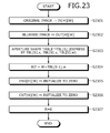
- Step S 2307 depicted in FIG. 23 replaces the operations at the steps described with reference to FIG. 9 having the same last two digits of the step number. The other steps are the same operations as those described with reference to FIG. 9 and therefore, will not be described.
- the image conversion apparatus 100 stores zero as R (step S 2307 ).
- steps S 2405 to S 2412 are obtained by replacing “X” with “Q” in the operations at steps S 1003 to S 1010 of FIG. 10 having the last two digits of the step number smaller by two.
- Step S 2408 is obtained by replacing “W” with “P” of step S 1006 .
- the image conversion apparatus 100 executes a P-acquisition process by using R as the argument (step S 2401 ). Details of the P-acquisition process will be described later with reference to FIG. 27 .
- the image conversion apparatus 100 stores zero as Q (step S 2402 ).
- the image conversion apparatus 100 executes an X/Y-acquisition process by using R and Q as the arguments (step S 2403 ).
- steps S 2503 and S 2507 to S 2510 are obtained by replacing “X” with “Q” in the operations at the steps described with reference to FIG. 11 having the same last two digits of the step number.
- Step S 2510 is obtained by replacing “W” with “P” of step S 1110 .
- the steps are not changed except the above points and therefore, will not be described.
- steps S 2610 and S 2611 are obtained by replacing “X” with “Q” in the operations at steps S 1208 and S 1209 described with reference to FIG. 12 .
- Step S 2614 is obtained by replacing “Y” with “R” of step S 1212 .
- the operations at steps S 2607 to S 2609 and S 2613 are the same as the operations at steps S 1205 to S 1207 and S 1211 described with reference to FIG. 12 and therefore, will not be described. Steps S 2601 to S 2606 will hereinafter be described.
- the image conversion apparatus 100 After termination of the execution of step S 2511 , the image conversion apparatus 100 stores an addition result of R and TBL[I] ⁇ y as R2 (step S 2601 ). The image conversion apparatus 100 executes a Ro-acquisition process by using R and R2 as the arguments (step S 2602 ). Details of the Ro-acquisition process will be described with reference to FIG. 29 .
- the image conversion apparatus 100 stores zero as Q (step S 2603 ).
- the image conversion apparatus 100 stores an addition result of Q and TBL[I] ⁇ x as Q2 (step S 2604 ).
- the image conversion apparatus 100 executes the X/Y-acquisition process by using R2 and Q2 as the arguments (step S 2605 ). By executing the X/Y-acquisition process by using R2 and Q2 as the arguments, the image conversion apparatus 100 can acquire X2 and Y2.
- the image conversion apparatus 100 determines whether Y2 is less than zero or Y2 is equal to or greater than H (step S 2606 ). If Y2 is equal to or greater than zero and Y2 is less than H (step S 2606 : NO), the image conversion apparatus 100 goes to the operation at step S 2607 . If Y2 is less than zero or Y2 is equal to or greater than H (step S 2606 : YES), the image conversion apparatus 100 goes to the operation at step S 2610 .
- the image conversion apparatus 100 determines whether R is less than an addition result of H and W as the operation at step S 805 , thereby determining “whether all the scanning lines have been processed”. If R is less than an addition result of H and W, an unprocessed scanning line is still present and the image conversion apparatus 100 executes the operation at step S 805 : NO. If R is equal to or greater than the sum of H and W, all the scanning lines have been processed and the image conversion apparatus 100 executes the operation at step S 805 : YES.
- FIG. 27 is a flowchart of an example of a P-acquisition process procedure.
- the P-acquisition process is a process of outputting a value of P by using R as the argument.
- the image conversion apparatus 100 determines whether R is less than W (step S 2701 ). If R is less than W (step S 2701 : YES), the image conversion apparatus 100 stores a value of R as P (step S 2702 ). If R is equal to or greater than W (step S 2701 : NO), the image conversion apparatus 100 determines whether R is larger than H (step S 2703 ). If R is equal to or greater than H (step S 2703 : NO), the image conversion apparatus 100 stores a value of W as P (step S 2704 ). If R is larger than H (step S 2703 : YES), the image conversion apparatus 100 stores a result of subtraction of R from an addition result of W and H as P (step S 2705 ).
- the image conversion apparatus 100 After execution of the operation at step S 2702 , the operation at step S 2704 , or the operation at step S 2705 , the image conversion apparatus 100 terminates the P-acquisition process. By executing the P-acquisition process, the image conversion apparatus 100 can obtain the value of P.
- FIG. 28 is a flowchart of an example of an X/Y-acquisition process procedure.
- the X/Y-acquisition process is a process of outputting values of X and Y by using R and Q as the arguments.
- the image conversion apparatus 100 determines whether R is equal to or less than H (step S 2801 ). If R is equal to or less than H (step S 2801 : YES), the image conversion apparatus 100 stores a value of Q as X (step S 2802 ). The image conversion apparatus 100 stores the difference of Q subtracted from R, as Y (step S 2803 ).
- step S 2801 If R is greater than H (step S 2801 : NO), the image conversion apparatus 100 stores the difference of subtracting H from the sum of Q+R, as X (step S 2804 ). The image conversion apparatus 100 stores the difference of subtracting Q from H, as Y (step S 2805 ). After execution of the operation at step S 2803 or the operation at step S 2805 , the image conversion apparatus 100 terminates the X/Y-acquisition process. By executing the X/Y-acquisition process, the image conversion apparatus 100 can obtain the values of X and Y.
- FIG. 29 is a flowchart of an example of a Ro-acquisition process procedure.
- the Ro-acquisition process is a process of outputting a value of Ro by using R and R2 as the arguments.
- the image conversion apparatus 100 determines if R is equal to or less than H (step S 2901 ). If R is equal to or less than H (step S 2901 : YES), the image conversion apparatus 100 determines whether R2 is equal to or less than H (step S 2902 ). If R2 is equal to or less than H (step S 2902 : YES), the image conversion apparatus 100 stores the difference of subtracting R2 from R, as Ro (step S 2903 ).
- step S 2901 determines if R2 is equal to or less than H (step S 2904 ). If R2 is greater than H (step S 2904 : NO), the image conversion apparatus 100 stores the difference of subtracting R2 from R, as Ro (step S 2905 ).
- step S 2902 If R2 is not equal to or less than H (step S 2902 : NO) or if R2 is equal to or less than H (step S 2904 : YES), the image conversion apparatus 100 stores the difference of subtracting 2 ⁇ H from the sum of R2 and R, as Ro (step S 2906 ). After execution of the operation at step S 2903 , step S 2905 , or step S 2906 , the image conversion apparatus 100 terminates the Ro-acquisition process. By executing the Ro-acquisition process, the image conversion apparatus 100 can acquire the value of Ro.
- the same pixel row is not scanned multiple times in FIGS. 4 to 29 , the same pixel row may be scanned multiple times. By scanning the same pixel row multiple times, diffusion other than the moving average can be achieved. An example of scanning the same pixel row multiple times will be described with reference to FIGS. 30 and 31 .
- FIG. 30 is an explanatory diagram of a third example of an aperture shape and a third example of storage contents of the aperture shape table.
- A) of FIG. 30 depicts diffusion coefficients when light diffuses in a quadrangular pyramid shape. A diffusion amount is large at a center portion and smaller toward the outside.
- B) of FIG. 30 depicts an example of storage contents of an aperture shape table 310 _ p when light diffuses in a quadrangular pyramid shape.
- the aperture shape table 310 _ p stores records 3001 - 1 to 3001 - 9 .
- FIG. 31 is an explanatory diagram of a fourth example of an aperture shape and a fourth example of storage contents of the aperture shape table.
- A of FIG. 31 depicts how light diffuses when Gaussian blur is applied.
- B of FIG. 31 depicts diffusion coefficients when Gaussian blur is applied.
- C of FIG. 31 depicts an example of storage contents of an aperture shape table 310 _ g when Gaussian blur is applied.
- the aperture shape table 310 _ g stores records 3101 - 1 to 3101 - 15 .
- the aperture shape table 310 _ g has n-fields storing information of magnification at the time of addition, along with the x-, y-, and w-fields.
- the process of conversion between the optical energy value and the RGB value will be described.
- IN[Y][X] may take one of 256 values from 0 to 255 and therefore, the process can be executed at high speed by reference to a conversion table.
- exptbl [90, 92, 95, 97, . . . , 52839] is obtained.
- the image conversion apparatus 100 obtains a value of exptbl[IN[Y][X]].
- Equation (3) a value of an optical energy value E is expressed by Equation (3).
- E 2 ⁇ n+a ⁇ 2 ⁇ ( n ⁇ 1)+ b ⁇ 2 ⁇ ( n ⁇ 2)+ c ⁇ 2 ⁇ ( n ⁇ 3)+ (3)
- Equation (3) can be converted into Equation (4).
- E 2 ⁇ n (1+ a/ 2+ b/ 4+ c/ 8+ . . . ) (4)
- log E n ⁇ log 2+log(1+ a/ 2+ b/ 4+ c/ 8+ . . . ) (5)
- a first term can be calculated by a simple multiplication.
- a second term has resolution defined by determining the number of elements a, b, c, . . . and can be obtained by referring to a table. Since log 2 is 0.693 and is less than one, it is difficult to directly calculate log 2 as an integer. Therefore, the image conversion apparatus 100 executes a process of retaining an appropriate value obtained by multiplication by M and subsequently dividing the value. Similarly, the image conversion apparatus 100 executes a process of creating a table of (log(1+a/2+b/4+ . . . )) with the same magnification for collective division. Once log E can be calculated, luminance D can easily be obtained.
- FIG. 32 is a flowchart (part 1) of an example of a procedure of the process of conversion from an optical energy value to an RGB value.
- the process of conversion from an optical energy value to an RGB value is a process of outputting an RGB value from an optical energy value.
- the image conversion apparatus 100 executes a process of changing expression of the optical energy value E into a format of (1+e/32) ⁇ 2 ⁇ m.
- the image conversion apparatus 100 stores zero as a multiplier m (step S 3201 ).
- the image conversion apparatus 100 stores one as a variable k indicative of 2 ⁇ m (step S 3202 ).
- the image conversion apparatus 100 determines whether E is equal to or greater than k (step S 3203 ). If E is less than k (step S 3203 : NO), the image conversion apparatus 100 increments a value of m (step S 3204 ).
- step S 3203 If E is equal to or greater than k (step S 3203 : YES), 2 ⁇ m is greater than E and therefore, the image conversion apparatus 100 decrements a value of m (step S 3206 ). By executing the operations to step S 3206 , m is obtained. Subsequently, e is obtained in FIG. 33 .
- FIG. 33 is a flowchart (part 2) of an example of a procedure of the process of conversion from an optical energy value to an RGB value.
- the image conversion apparatus 100 stores a value of E as e (step S 3301 ).
- the process of steps S 3302 to S 3305 is a process of extracting an integer expressed by the lower five bits from the m ⁇ 1 bit of e.
- step S 3302 the image conversion apparatus 100 determines whether m is less than five (step S 3302 ).
- the operation at step S 3302 is a process of determining whether e is a number of six or more digits in binary. Since m is counted as 0, 1, 2, . . . , a digit number is represented by m+1.
- 40*4*log 2 is about 111 and a value of 40*4*log(l+e/32) is stored in a table log tbl. Therefore, the image conversion apparatus 100 calculates (m*111+log tbl[e])/4 ⁇ 180 and stores the calculation result as the luminance d (step S 3306 ).
- the image conversion apparatus 100 checks whether the luminance d is within the range at steps S 3307 to S 3310 . For example, the image conversion apparatus 100 checks whether d is less than zero (step S 3307 ). If d is less than zero (step S 3307 : YES), the image conversion apparatus 100 stores zero as d (step S 3308 ). If d is equal to or greater than zero (step S 3307 : NO), the image conversion apparatus 100 determines whether d is larger than 255 (step S 3309 ).
- step S 3309 YES
- the image conversion apparatus 100 stores 255 as d (step S 3310 ). If d is equal to or less than 255 (step S 3309 : NO), or if the operation at step S 3308 is terminated, or if the operation at step S 3310 is terminated, the image conversion apparatus 100 terminates the process of conversion from an optical energy value to an RGB value.
- the image conversion apparatus 100 can execute the process of conversion at a speed higher than by Equation (2).
- FIG. 34 is an explanatory diagram (part 1) of an example of a result of the image conversion process of the present embodiment.
- FIG. 34 depicts an original image 3401 _IN, an original image 3402 _IN, a blurred image 3401 _OUT, and a blurred image 3402 _OUT when the aperture shape is hexagonal.
- White portions in the original image 3401 _IN and the original image 3402 _IN are dispersed as white regions in a hexagonal shape in the blurred image 3401 _OUT and the blurred image 3402 _OUT.
- FIG. 35 is an explanatory diagram (part 2) of an example of a result of the image conversion process of the present embodiment.
- FIG. 35 depicts an original image 3501 _IN, and blurred images 3501 _ 5 _OUT to 3501 _ 41 _OUT.
- “x” of a blurred images 3501 _ x _OUT indicates a size of the aperture shape.
- White portions of the original image 3501 _IN become larger in a hexagonal shape on the blurred images as a size of the aperture shape becomes larger.
- FIG. 36 is an explanatory diagram of comparison of the speed between an image conversion process on the basis of a pixel and the image conversion process of the present embodiment.
- FIG. 36 depicts the processing time when an original image with 322 [pixels] ⁇ 482 [pixels] is converted into a blurred image with a hexagonal aperture shape.
- the image conversion process on the basis of a pixel is a process of conversion into a blurred image without using a calculation result.
- a graph 3601 of the processing time of the image conversion process on the basis of a pixel on FIG. 36 indicates that the processing time becomes longer as the size of the aperture shape becomes larger. For example, when the size of the aperture shape is 20 [pixels], the processing time of the image conversion process on the basis of a pixel is 1200 [msec].
- a graph 3602 of the processing time of the image conversion process of the present embodiment indicates that a short processing time can be maintained even when the size of the aperture shape becomes larger. For example, when the size of the aperture shape is 20 [pixels], the processing time of the image conversion process of the present embodiment is about 50 [msec].
- the image conversion apparatus 100 uses a conversion result of a first pixel in a first pixel row overlapping an aperture shape to convert a second pixel in a second pixel row at a relative position coinciding with the first pixel in a region overlapping the aperture shape.
- an affecting pixel is common to the first pixel and the second pixel and therefore, for example, the image conversion apparatus 100 can directly reuse the conversion result of the first pixel to reduce the calculation amount during image conversion.
- the image conversion apparatus 100 may calculate a value of the second pixel after conversion by using a value of the first pixel that is obtained from conversion of the original image and that is calculated based on a value of a pixel overlapping the given pixel when the aperture shape is moved such that the first pixel is included. As a result, the image conversion apparatus 100 can calculate a reusable conversion result of the first pixel to reuse the conversion result of the first pixel at the time of calculation of the value of the second pixel and therefore, the calculation amount during image conversion can be reduced.
- the image conversion apparatus 100 may calculate the value of the second pixel after conversion based on a value of the first pixel in the case of converting the original image and the value of a pixel overlapping the given pixel when the aperture shape is moved such that the second pixel is included. As a result, if a pixel group affecting the second pixel is entirely included in pixels affecting the first pixel, the image conversion apparatus 100 can reuse the conversion result of the first pixel to reduce the calculation amount during image conversion.
- the image conversion apparatus 100 calculates a value of each of the respective pixels after conversion based on values of pixels from each of the respective pixels to a pixel advanced by the pixel count of the first pixel group in either the scanning direction or the direction opposite to the scanning direction. Subsequently, among the values of the respective pixels after conversion, the image conversion apparatus 100 may set as the value of the first pixel, the value of the pixel at a position advanced from the diffusion source pixel in the direction opposite to the given direction by the number of pixels from the pixel at the end in the given direction in the first pixel group to the first pixel.
- the image conversion apparatus 100 collectively calculates the moving average for each line and therefore, accesses a continuous region, thereby achieving a higher process speed. If access to a continuous region is available, for example, the region is more likely to be present in a cache line and therefore, the high-speed image conversion process can be achieved.
- the image conversion apparatus 100 may calculate a value of each of the respective pixels after conversion based on values of pixels from each of the respective pixels to the pixel advanced by the pixel count of the second pixel group, based on a value of each of the respective pixels after conversion calculated by using the pixel count of the first pixel group. As a result, the image conversion apparatus 100 can reuse an already calculated moving average and therefore, can reduce the calculation amount.
- the image conversion apparatus 100 may execute the image conversion process according to the scanning direction corresponding to the shape specified by a user. For example, if the number of records of the aperture shape table 310 becomes smaller when the shape specified by the user is scanned along the y-axis rather than being scanned along the x-axis, the image conversion apparatus 100 can select the y-axis as the scanning direction to reduce the calculation amount. The scan along the y-axis and the scan along the x-axis may result in the same number of records of the aperture shape table 310 . In this case, the image conversion apparatus 100 can select the x-axis direction enabling a process of a continuous region as the scanning direction, thereby achieving the high-speed image conversion process.
- the image conversion process according to the present embodiment reduces the calculation amount, the image conversion process can be completed in a short time without causing stress to the user even when being executed on a portable terminal with a low CPU processing capability, such as a smartphone and a mobile telephone.
- the image conversion process according to the present embodiment may be executed on a personal computer. For example, if a photographic image is processed, a foreground and a background may be divided by another application capable of dividing a foreground and a background and the image conversion process according to the present embodiment may be executed for the background. This enables user to acquire an excellent blurred image like those taken by a camera in a short time.
- the image conversion method described in the present embodiment may be implemented by executing a prepared program on a computer such as a personal computer and a workstation.
- the program is stored on a non-transitory, computer-readable recording medium such as a hard disk, a flexible disk, a CD-ROM, an MO, and a DVD, read out from the recording medium, and executed by the computer.
- the program may be distributed through a network such as the Internet.
- An aspect of the present invention produces an effect that the processing time of the process of giving a blurring effect can be reduced.
Landscapes
- Engineering & Computer Science (AREA)
- Physics & Mathematics (AREA)
- General Physics & Mathematics (AREA)
- Theoretical Computer Science (AREA)
- Multimedia (AREA)
- Signal Processing (AREA)
- Image Processing (AREA)
- Facsimile Image Signal Circuits (AREA)
Applications Claiming Priority (1)
| Application Number | Priority Date | Filing Date | Title |
|---|---|---|---|
| PCT/JP2012/071917 WO2014033867A1 (ja) | 2012-08-29 | 2012-08-29 | 画像変換プログラム、記録媒体、画像変換装置、および画像変換方法 |
Related Parent Applications (1)
| Application Number | Title | Priority Date | Filing Date |
|---|---|---|---|
| PCT/JP2012/071917 Continuation WO2014033867A1 (ja) | 2012-08-29 | 2012-08-29 | 画像変換プログラム、記録媒体、画像変換装置、および画像変換方法 |
Publications (2)
| Publication Number | Publication Date |
|---|---|
| US20150156436A1 US20150156436A1 (en) | 2015-06-04 |
| US9615046B2 true US9615046B2 (en) | 2017-04-04 |
Family
ID=50182717
Family Applications (1)
| Application Number | Title | Priority Date | Filing Date |
|---|---|---|---|
| US14/619,868 Expired - Fee Related US9615046B2 (en) | 2012-08-29 | 2015-02-11 | Image conversion apparatus and method reducing number of pixel counts processing |
Country Status (4)
| Country | Link |
|---|---|
| US (1) | US9615046B2 (ja) |
| EP (1) | EP2892025B1 (ja) |
| JP (1) | JP5900625B2 (ja) |
| WO (1) | WO2014033867A1 (ja) |
Families Citing this family (1)
| Publication number | Priority date | Publication date | Assignee | Title |
|---|---|---|---|---|
| KR102377277B1 (ko) * | 2015-02-27 | 2022-03-23 | 삼성전자주식회사 | 전자 장치에서 커뮤니케이션 지원 방법 및 장치 |
Citations (8)
| Publication number | Priority date | Publication date | Assignee | Title |
|---|---|---|---|---|
| JPH0636022A (ja) | 1992-07-14 | 1994-02-10 | Matsushita Electric Ind Co Ltd | 画像ぼかし処理装置 |
| JPH08272960A (ja) | 1995-03-29 | 1996-10-18 | Dainippon Screen Mfg Co Ltd | 画像のフィルタリング処理方法 |
| JP2001216513A (ja) | 2000-02-01 | 2001-08-10 | Yasumi Ichimura | ぼけと絞り形状画像変換装置および方法 |
| JP2004133551A (ja) | 2002-10-08 | 2004-04-30 | Noritsu Koki Co Ltd | 画像処理方法、画像処理装置、画像処理プログラム、および画像処理プログラムを記録した記録媒体 |
| US20080118175A1 (en) * | 2006-11-16 | 2008-05-22 | Barinder Singh Rai | Creating A Variable Motion Blur Effect |
| US20090060387A1 (en) | 2007-09-04 | 2009-03-05 | Microsoft Corporation | Optimizations for radius optical blur |
| US20110075905A1 (en) * | 2009-09-29 | 2011-03-31 | Yasuhiro Noshi | X-ray computed tomography apparatus and image processing method |
| US8199223B2 (en) * | 2009-04-08 | 2012-06-12 | Olympus Corporation | Image processing device, image processing method, and computer readable storage medium storing image processing program |
-
2012
- 2012-08-29 EP EP12883620.2A patent/EP2892025B1/en not_active Not-in-force
- 2012-08-29 WO PCT/JP2012/071917 patent/WO2014033867A1/ja active Application Filing
- 2012-08-29 JP JP2014532643A patent/JP5900625B2/ja not_active Expired - Fee Related
-
2015
- 2015-02-11 US US14/619,868 patent/US9615046B2/en not_active Expired - Fee Related
Patent Citations (9)
| Publication number | Priority date | Publication date | Assignee | Title |
|---|---|---|---|---|
| JPH0636022A (ja) | 1992-07-14 | 1994-02-10 | Matsushita Electric Ind Co Ltd | 画像ぼかし処理装置 |
| JPH08272960A (ja) | 1995-03-29 | 1996-10-18 | Dainippon Screen Mfg Co Ltd | 画像のフィルタリング処理方法 |
| JP2001216513A (ja) | 2000-02-01 | 2001-08-10 | Yasumi Ichimura | ぼけと絞り形状画像変換装置および方法 |
| US20010016082A1 (en) | 2000-02-01 | 2001-08-23 | Yasuumi Ichimura | Process for making images defocused |
| JP2004133551A (ja) | 2002-10-08 | 2004-04-30 | Noritsu Koki Co Ltd | 画像処理方法、画像処理装置、画像処理プログラム、および画像処理プログラムを記録した記録媒体 |
| US20080118175A1 (en) * | 2006-11-16 | 2008-05-22 | Barinder Singh Rai | Creating A Variable Motion Blur Effect |
| US20090060387A1 (en) | 2007-09-04 | 2009-03-05 | Microsoft Corporation | Optimizations for radius optical blur |
| US8199223B2 (en) * | 2009-04-08 | 2012-06-12 | Olympus Corporation | Image processing device, image processing method, and computer readable storage medium storing image processing program |
| US20110075905A1 (en) * | 2009-09-29 | 2011-03-31 | Yasuhiro Noshi | X-ray computed tomography apparatus and image processing method |
Non-Patent Citations (2)
| Title |
|---|
| Extended European Search Report dated Jul. 20, 2015 in corresponding European Patent Application No. 12883620.2. |
| International Search Report mailed Nov. 13, 2012 in corresponding international application PCT/JP2012/071917. |
Also Published As
| Publication number | Publication date |
|---|---|
| US20150156436A1 (en) | 2015-06-04 |
| WO2014033867A1 (ja) | 2014-03-06 |
| EP2892025A4 (en) | 2015-08-19 |
| EP2892025A1 (en) | 2015-07-08 |
| EP2892025B1 (en) | 2017-04-19 |
| JP5900625B2 (ja) | 2016-04-06 |
| JPWO2014033867A1 (ja) | 2016-08-08 |
Similar Documents
| Publication | Publication Date | Title |
|---|---|---|
| US10861133B1 (en) | Super-resolution video reconstruction method, device, apparatus and computer-readable storage medium | |
| KR102475212B1 (ko) | 타일식 아키텍처들에서의 포비티드 렌더링 | |
| CN106251392B (zh) | 用于执行交织的方法和设备 | |
| US9082180B2 (en) | System, method, and computer program product for implementing a spatially varying unsharp mask noise reduction filter | |
| Ragan-Kelley et al. | Decoupling algorithms from schedules for easy optimization of image processing pipelines | |
| JP6352546B2 (ja) | 非整列ブロック転送動作の処理 | |
| CN111727424A (zh) | 跨显示屏的自适应界面转换 | |
| US7605825B1 (en) | Fast zoom-adaptable anti-aliasing of lines using a graphics processing unit | |
| US10186068B2 (en) | Method, apparatus and system for rendering an image | |
| JPWO2003001458A1 (ja) | 情報処理装置 | |
| US9727982B2 (en) | Parallelising per-pixel compositing | |
| CN111788554A (zh) | 跨显示屏的自适应界面转换 | |
| CN113506305B (zh) | 三维点云数据的图像增强方法、语义分割方法及装置 | |
| US20030122829A1 (en) | Efficient movement of fragment stamp | |
| US20090322781A1 (en) | Anti-aliasing techniques for image processing | |
| US9615046B2 (en) | Image conversion apparatus and method reducing number of pixel counts processing | |
| US10127001B2 (en) | Virtualizing applications for per-monitor displaying | |
| KR102405309B1 (ko) | 디스플레이 장치 및 그 디스플레이 방법 | |
| Lan et al. | Parallel implementations of structural similarity based no-reference image quality assessment | |
| TWI722684B (zh) | 關於影像處理器複雜傳遞函數之電腦實施之方法及非暫時性電腦儲存媒體及採用影像處理器之運算裝置 | |
| US20140354627A1 (en) | Rendering a 3d shape | |
| Nagy et al. | OpenCV C# wrapper based video enhancement using different optical flow methods in the super-resolution | |
| CN111091570B (zh) | 图像分割标注方法、装置、设备及存储介质 | |
| US9811945B2 (en) | On-demand transformation aware shape tessellation | |
| CN115063509A (zh) | 一种基于daa直线表示的光栅化方法、装置及存储介质 |
Legal Events
| Date | Code | Title | Description |
|---|---|---|---|
| AS | Assignment |
Owner name: FUJITSU LIMITED, JAPAN Free format text: ASSIGNMENT OF ASSIGNORS INTEREST;ASSIGNORS:SENTA, YOSUKE;KIKUCHI, TARO;KOIKE, HIDEYUKI;SIGNING DATES FROM 20150106 TO 20150120;REEL/FRAME:034948/0829 |
|
| STCF | Information on status: patent grant |
Free format text: PATENTED CASE |
|
| FEPP | Fee payment procedure |
Free format text: MAINTENANCE FEE REMINDER MAILED (ORIGINAL EVENT CODE: REM.); ENTITY STATUS OF PATENT OWNER: LARGE ENTITY |
|
| LAPS | Lapse for failure to pay maintenance fees |
Free format text: PATENT EXPIRED FOR FAILURE TO PAY MAINTENANCE FEES (ORIGINAL EVENT CODE: EXP.); ENTITY STATUS OF PATENT OWNER: LARGE ENTITY |
|
| STCH | Information on status: patent discontinuation |
Free format text: PATENT EXPIRED DUE TO NONPAYMENT OF MAINTENANCE FEES UNDER 37 CFR 1.362 |
|
| FP | Lapsed due to failure to pay maintenance fee |
Effective date: 20210404 |