US9613896B2 - Semiconductor memory device with conductive columnar body - Google Patents
Semiconductor memory device with conductive columnar body Download PDFInfo
- Publication number
- US9613896B2 US9613896B2 US14/730,640 US201514730640A US9613896B2 US 9613896 B2 US9613896 B2 US 9613896B2 US 201514730640 A US201514730640 A US 201514730640A US 9613896 B2 US9613896 B2 US 9613896B2
- Authority
- US
- United States
- Prior art keywords
- columnar body
- region
- cell array
- conductive layer
- directions
- Prior art date
- Legal status (The legal status is an assumption and is not a legal conclusion. Google has not performed a legal analysis and makes no representation as to the accuracy of the status listed.)
- Active
Links
- 239000004065 semiconductor Substances 0.000 title claims abstract description 64
- 230000000149 penetrating effect Effects 0.000 claims abstract description 12
- 239000000758 substrate Substances 0.000 claims abstract description 11
- 239000010410 layer Substances 0.000 claims description 122
- 239000011229 interlayer Substances 0.000 claims description 27
- 238000009825 accumulation Methods 0.000 claims description 7
- WFKWXMTUELFFGS-UHFFFAOYSA-N tungsten Chemical compound [W] WFKWXMTUELFFGS-UHFFFAOYSA-N 0.000 claims description 7
- 229910052721 tungsten Inorganic materials 0.000 claims description 7
- 239000010937 tungsten Substances 0.000 claims description 7
- 239000000463 material Substances 0.000 claims description 5
- VYPSYNLAJGMNEJ-UHFFFAOYSA-N Silicium dioxide Chemical compound O=[Si]=O VYPSYNLAJGMNEJ-UHFFFAOYSA-N 0.000 description 10
- 229910052814 silicon oxide Inorganic materials 0.000 description 10
- 230000006870 function Effects 0.000 description 9
- 229910052581 Si3N4 Inorganic materials 0.000 description 6
- 230000000052 comparative effect Effects 0.000 description 6
- HQVNEWCFYHHQES-UHFFFAOYSA-N silicon nitride Chemical compound N12[Si]34N5[Si]62N3[Si]51N64 HQVNEWCFYHHQES-UHFFFAOYSA-N 0.000 description 6
- 239000004020 conductor Substances 0.000 description 5
- 238000004519 manufacturing process Methods 0.000 description 5
- 230000008901 benefit Effects 0.000 description 3
- 229910021420 polycrystalline silicon Inorganic materials 0.000 description 3
- 229920005591 polysilicon Polymers 0.000 description 3
- NBIIXXVUZAFLBC-UHFFFAOYSA-N Phosphoric acid Chemical compound OP(O)(O)=O NBIIXXVUZAFLBC-UHFFFAOYSA-N 0.000 description 2
- 229910000577 Silicon-germanium Inorganic materials 0.000 description 2
- GWEVSGVZZGPLCZ-UHFFFAOYSA-N Titan oxide Chemical compound O=[Ti]=O GWEVSGVZZGPLCZ-UHFFFAOYSA-N 0.000 description 2
- MCMNRKCIXSYSNV-UHFFFAOYSA-N Zirconium dioxide Chemical compound O=[Zr]=O MCMNRKCIXSYSNV-UHFFFAOYSA-N 0.000 description 2
- 238000000151 deposition Methods 0.000 description 2
- 238000010586 diagram Methods 0.000 description 2
- 238000005516 engineering process Methods 0.000 description 2
- 238000000034 method Methods 0.000 description 2
- 239000011800 void material Substances 0.000 description 2
- 229910017121 AlSiO Inorganic materials 0.000 description 1
- OKTJSMMVPCPJKN-UHFFFAOYSA-N Carbon Chemical compound [C] OKTJSMMVPCPJKN-UHFFFAOYSA-N 0.000 description 1
- 229910003855 HfAlO Inorganic materials 0.000 description 1
- 229910004129 HfSiO Inorganic materials 0.000 description 1
- XUIMIQQOPSSXEZ-UHFFFAOYSA-N Silicon Chemical compound [Si] XUIMIQQOPSSXEZ-UHFFFAOYSA-N 0.000 description 1
- 229910007875 ZrAlO Inorganic materials 0.000 description 1
- 229910006501 ZrSiO Inorganic materials 0.000 description 1
- LEVVHYCKPQWKOP-UHFFFAOYSA-N [Si].[Ge] Chemical compound [Si].[Ge] LEVVHYCKPQWKOP-UHFFFAOYSA-N 0.000 description 1
- PNEYBMLMFCGWSK-UHFFFAOYSA-N aluminium oxide Inorganic materials [O-2].[O-2].[O-2].[Al+3].[Al+3] PNEYBMLMFCGWSK-UHFFFAOYSA-N 0.000 description 1
- 229910000147 aluminium phosphate Inorganic materials 0.000 description 1
- 229910052799 carbon Inorganic materials 0.000 description 1
- CETPSERCERDGAM-UHFFFAOYSA-N ceric oxide Chemical compound O=[Ce]=O CETPSERCERDGAM-UHFFFAOYSA-N 0.000 description 1
- 229910000421 cerium(III) oxide Inorganic materials 0.000 description 1
- 229910000422 cerium(IV) oxide Inorganic materials 0.000 description 1
- 229910052593 corundum Inorganic materials 0.000 description 1
- 230000008021 deposition Effects 0.000 description 1
- 238000001312 dry etching Methods 0.000 description 1
- CMIHHWBVHJVIGI-UHFFFAOYSA-N gadolinium(III) oxide Inorganic materials [O-2].[O-2].[O-2].[Gd+3].[Gd+3] CMIHHWBVHJVIGI-UHFFFAOYSA-N 0.000 description 1
- 229910052732 germanium Inorganic materials 0.000 description 1
- GNPVGFCGXDBREM-UHFFFAOYSA-N germanium atom Chemical compound [Ge] GNPVGFCGXDBREM-UHFFFAOYSA-N 0.000 description 1
- CJNBYAVZURUTKZ-UHFFFAOYSA-N hafnium(IV) oxide Inorganic materials O=[Hf]=O CJNBYAVZURUTKZ-UHFFFAOYSA-N 0.000 description 1
- MRELNEQAGSRDBK-UHFFFAOYSA-N lanthanum oxide Inorganic materials [O-2].[O-2].[O-2].[La+3].[La+3] MRELNEQAGSRDBK-UHFFFAOYSA-N 0.000 description 1
- 238000001459 lithography Methods 0.000 description 1
- 238000012986 modification Methods 0.000 description 1
- 230000004048 modification Effects 0.000 description 1
- KTUFCUMIWABKDW-UHFFFAOYSA-N oxo(oxolanthaniooxy)lanthanum Chemical compound O=[La]O[La]=O KTUFCUMIWABKDW-UHFFFAOYSA-N 0.000 description 1
- 238000004904 shortening Methods 0.000 description 1
- 229910052710 silicon Inorganic materials 0.000 description 1
- 239000010703 silicon Substances 0.000 description 1
- HBMJWWWQQXIZIP-UHFFFAOYSA-N silicon carbide Chemical compound [Si+]#[C-] HBMJWWWQQXIZIP-UHFFFAOYSA-N 0.000 description 1
- 238000006467 substitution reaction Methods 0.000 description 1
- PBCFLUZVCVVTBY-UHFFFAOYSA-N tantalum pentoxide Inorganic materials O=[Ta](=O)O[Ta](=O)=O PBCFLUZVCVVTBY-UHFFFAOYSA-N 0.000 description 1
- 238000001039 wet etching Methods 0.000 description 1
- 229910001845 yogo sapphire Inorganic materials 0.000 description 1
- RUDFQVOCFDJEEF-UHFFFAOYSA-N yttrium(III) oxide Inorganic materials [O-2].[O-2].[O-2].[Y+3].[Y+3] RUDFQVOCFDJEEF-UHFFFAOYSA-N 0.000 description 1
Images


Classifications
-
- H—ELECTRICITY
- H01—ELECTRIC ELEMENTS
- H01L—SEMICONDUCTOR DEVICES NOT COVERED BY CLASS H10
- H01L23/00—Details of semiconductor or other solid state devices
- H01L23/52—Arrangements for conducting electric current within the device in operation from one component to another, i.e. interconnections, e.g. wires, lead frames
- H01L23/522—Arrangements for conducting electric current within the device in operation from one component to another, i.e. interconnections, e.g. wires, lead frames including external interconnections consisting of a multilayer structure of conductive and insulating layers inseparably formed on the semiconductor body
- H01L23/5221—Crossover interconnections
-
- H—ELECTRICITY
- H10—SEMICONDUCTOR DEVICES; ELECTRIC SOLID-STATE DEVICES NOT OTHERWISE PROVIDED FOR
- H10B—ELECTRONIC MEMORY DEVICES
- H10B41/00—Electrically erasable-and-programmable ROM [EEPROM] devices comprising floating gates
- H10B41/10—Electrically erasable-and-programmable ROM [EEPROM] devices comprising floating gates characterised by the top-view layout
-
- H—ELECTRICITY
- H10—SEMICONDUCTOR DEVICES; ELECTRIC SOLID-STATE DEVICES NOT OTHERWISE PROVIDED FOR
- H10B—ELECTRONIC MEMORY DEVICES
- H10B43/00—EEPROM devices comprising charge-trapping gate insulators
- H10B43/50—EEPROM devices comprising charge-trapping gate insulators characterised by the boundary region between the core and peripheral circuit regions
-
- H—ELECTRICITY
- H01—ELECTRIC ELEMENTS
- H01L—SEMICONDUCTOR DEVICES NOT COVERED BY CLASS H10
- H01L21/00—Processes or apparatus adapted for the manufacture or treatment of semiconductor or solid state devices or of parts thereof
- H01L21/70—Manufacture or treatment of devices consisting of a plurality of solid state components formed in or on a common substrate or of parts thereof; Manufacture of integrated circuit devices or of parts thereof
- H01L21/77—Manufacture or treatment of devices consisting of a plurality of solid state components or integrated circuits formed in, or on, a common substrate
- H01L21/78—Manufacture or treatment of devices consisting of a plurality of solid state components or integrated circuits formed in, or on, a common substrate with subsequent division of the substrate into plural individual devices
- H01L21/82—Manufacture or treatment of devices consisting of a plurality of solid state components or integrated circuits formed in, or on, a common substrate with subsequent division of the substrate into plural individual devices to produce devices, e.g. integrated circuits, each consisting of a plurality of components
- H01L21/822—Manufacture or treatment of devices consisting of a plurality of solid state components or integrated circuits formed in, or on, a common substrate with subsequent division of the substrate into plural individual devices to produce devices, e.g. integrated circuits, each consisting of a plurality of components the substrate being a semiconductor, using silicon technology
- H01L21/8221—Three dimensional integrated circuits stacked in different levels
-
- H—ELECTRICITY
- H01—ELECTRIC ELEMENTS
- H01L—SEMICONDUCTOR DEVICES NOT COVERED BY CLASS H10
- H01L23/00—Details of semiconductor or other solid state devices
- H01L23/52—Arrangements for conducting electric current within the device in operation from one component to another, i.e. interconnections, e.g. wires, lead frames
- H01L23/522—Arrangements for conducting electric current within the device in operation from one component to another, i.e. interconnections, e.g. wires, lead frames including external interconnections consisting of a multilayer structure of conductive and insulating layers inseparably formed on the semiconductor body
- H01L23/5226—Via connections in a multilevel interconnection structure
-
- H—ELECTRICITY
- H01—ELECTRIC ELEMENTS
- H01L—SEMICONDUCTOR DEVICES NOT COVERED BY CLASS H10
- H01L23/00—Details of semiconductor or other solid state devices
- H01L23/52—Arrangements for conducting electric current within the device in operation from one component to another, i.e. interconnections, e.g. wires, lead frames
- H01L23/522—Arrangements for conducting electric current within the device in operation from one component to another, i.e. interconnections, e.g. wires, lead frames including external interconnections consisting of a multilayer structure of conductive and insulating layers inseparably formed on the semiconductor body
- H01L23/528—Geometry or layout of the interconnection structure
-
- H—ELECTRICITY
- H01—ELECTRIC ELEMENTS
- H01L—SEMICONDUCTOR DEVICES NOT COVERED BY CLASS H10
- H01L27/00—Devices consisting of a plurality of semiconductor or other solid-state components formed in or on a common substrate
- H01L27/02—Devices consisting of a plurality of semiconductor or other solid-state components formed in or on a common substrate including semiconductor components specially adapted for rectifying, oscillating, amplifying or switching and having potential barriers; including integrated passive circuit elements having potential barriers
- H01L27/04—Devices consisting of a plurality of semiconductor or other solid-state components formed in or on a common substrate including semiconductor components specially adapted for rectifying, oscillating, amplifying or switching and having potential barriers; including integrated passive circuit elements having potential barriers the substrate being a semiconductor body
- H01L27/06—Devices consisting of a plurality of semiconductor or other solid-state components formed in or on a common substrate including semiconductor components specially adapted for rectifying, oscillating, amplifying or switching and having potential barriers; including integrated passive circuit elements having potential barriers the substrate being a semiconductor body including a plurality of individual components in a non-repetitive configuration
- H01L27/0688—Integrated circuits having a three-dimensional layout
-
- H01L27/11524—
-
- H01L27/11551—
-
- H01L27/1157—
-
- H01L27/11578—
-
- H01L27/2481—
-
- H—ELECTRICITY
- H10—SEMICONDUCTOR DEVICES; ELECTRIC SOLID-STATE DEVICES NOT OTHERWISE PROVIDED FOR
- H10B—ELECTRONIC MEMORY DEVICES
- H10B41/00—Electrically erasable-and-programmable ROM [EEPROM] devices comprising floating gates
- H10B41/20—Electrically erasable-and-programmable ROM [EEPROM] devices comprising floating gates characterised by three-dimensional arrangements, e.g. with cells on different height levels
- H10B41/23—Electrically erasable-and-programmable ROM [EEPROM] devices comprising floating gates characterised by three-dimensional arrangements, e.g. with cells on different height levels with source and drain on different levels, e.g. with sloping channels
- H10B41/27—Electrically erasable-and-programmable ROM [EEPROM] devices comprising floating gates characterised by three-dimensional arrangements, e.g. with cells on different height levels with source and drain on different levels, e.g. with sloping channels the channels comprising vertical portions, e.g. U-shaped channels
-
- H—ELECTRICITY
- H10—SEMICONDUCTOR DEVICES; ELECTRIC SOLID-STATE DEVICES NOT OTHERWISE PROVIDED FOR
- H10B—ELECTRONIC MEMORY DEVICES
- H10B41/00—Electrically erasable-and-programmable ROM [EEPROM] devices comprising floating gates
- H10B41/30—Electrically erasable-and-programmable ROM [EEPROM] devices comprising floating gates characterised by the memory core region
- H10B41/35—Electrically erasable-and-programmable ROM [EEPROM] devices comprising floating gates characterised by the memory core region with a cell select transistor, e.g. NAND
-
- H—ELECTRICITY
- H10—SEMICONDUCTOR DEVICES; ELECTRIC SOLID-STATE DEVICES NOT OTHERWISE PROVIDED FOR
- H10B—ELECTRONIC MEMORY DEVICES
- H10B41/00—Electrically erasable-and-programmable ROM [EEPROM] devices comprising floating gates
- H10B41/50—Electrically erasable-and-programmable ROM [EEPROM] devices comprising floating gates characterised by the boundary region between the core region and the peripheral circuit region
-
- H—ELECTRICITY
- H10—SEMICONDUCTOR DEVICES; ELECTRIC SOLID-STATE DEVICES NOT OTHERWISE PROVIDED FOR
- H10B—ELECTRONIC MEMORY DEVICES
- H10B43/00—EEPROM devices comprising charge-trapping gate insulators
- H10B43/10—EEPROM devices comprising charge-trapping gate insulators characterised by the top-view layout
-
- H—ELECTRICITY
- H10—SEMICONDUCTOR DEVICES; ELECTRIC SOLID-STATE DEVICES NOT OTHERWISE PROVIDED FOR
- H10B—ELECTRONIC MEMORY DEVICES
- H10B43/00—EEPROM devices comprising charge-trapping gate insulators
- H10B43/20—EEPROM devices comprising charge-trapping gate insulators characterised by three-dimensional arrangements, e.g. with cells on different height levels
- H10B43/23—EEPROM devices comprising charge-trapping gate insulators characterised by three-dimensional arrangements, e.g. with cells on different height levels with source and drain on different levels, e.g. with sloping channels
- H10B43/27—EEPROM devices comprising charge-trapping gate insulators characterised by three-dimensional arrangements, e.g. with cells on different height levels with source and drain on different levels, e.g. with sloping channels the channels comprising vertical portions, e.g. U-shaped channels
-
- H—ELECTRICITY
- H10—SEMICONDUCTOR DEVICES; ELECTRIC SOLID-STATE DEVICES NOT OTHERWISE PROVIDED FOR
- H10B—ELECTRONIC MEMORY DEVICES
- H10B43/00—EEPROM devices comprising charge-trapping gate insulators
- H10B43/30—EEPROM devices comprising charge-trapping gate insulators characterised by the memory core region
- H10B43/35—EEPROM devices comprising charge-trapping gate insulators characterised by the memory core region with cell select transistors, e.g. NAND
-
- H—ELECTRICITY
- H10—SEMICONDUCTOR DEVICES; ELECTRIC SOLID-STATE DEVICES NOT OTHERWISE PROVIDED FOR
- H10B—ELECTRONIC MEMORY DEVICES
- H10B63/00—Resistance change memory devices, e.g. resistive RAM [ReRAM] devices
- H10B63/80—Arrangements comprising multiple bistable or multi-stable switching components of the same type on a plane parallel to the substrate, e.g. cross-point arrays
- H10B63/84—Arrangements comprising multiple bistable or multi-stable switching components of the same type on a plane parallel to the substrate, e.g. cross-point arrays arranged in a direction perpendicular to the substrate, e.g. 3D cell arrays
-
- H—ELECTRICITY
- H01—ELECTRIC ELEMENTS
- H01L—SEMICONDUCTOR DEVICES NOT COVERED BY CLASS H10
- H01L2224/00—Indexing scheme for arrangements for connecting or disconnecting semiconductor or solid-state bodies and methods related thereto as covered by H01L24/00
- H01L2224/01—Means for bonding being attached to, or being formed on, the surface to be connected, e.g. chip-to-package, die-attach, "first-level" interconnects; Manufacturing methods related thereto
- H01L2224/26—Layer connectors, e.g. plate connectors, solder or adhesive layers; Manufacturing methods related thereto
- H01L2224/31—Structure, shape, material or disposition of the layer connectors after the connecting process
- H01L2224/32—Structure, shape, material or disposition of the layer connectors after the connecting process of an individual layer connector
- H01L2224/321—Disposition
- H01L2224/32135—Disposition the layer connector connecting between different semiconductor or solid-state bodies, i.e. chip-to-chip
- H01L2224/32145—Disposition the layer connector connecting between different semiconductor or solid-state bodies, i.e. chip-to-chip the bodies being stacked
Definitions
- An embodiment of the present invention relates to a semiconductor memory device.
- One kind of semiconductor memory device is a flash memory.
- a NAND type flash memory in particular is widely used since it is low cost and has a large capacity.
- many technologies for further increasing the capacity of this NAND type flash memory have been proposed.
- One such technology is a structure in which memory cells are three-dimensionally disposed.
- FIG. 1 is a view showing functional blocks of a semiconductor memory device according to an embodiment.
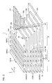
- FIG. 2 is a perspective view showing a structure of a memory cell array in the semiconductor memory device according to the embodiment.
- FIG. 3 is a perspective view showing a structure of a memory columnar body and a periphery thereof, of the memory cell array in the semiconductor memory device according to the embodiment.
- FIG. 4 is an equivalent circuit diagram of a memory unit of the memory cell array in the semiconductor memory device according to the embodiment.
- FIGS. 5 to 7 are cross-sectional views of the memory cell array in the semiconductor memory device according to the embodiment.
- FIGS. 8 to 23 are cross-sectional views explaining manufacturing steps of the memory cell array in the semiconductor memory device according to the embodiment.
- FIG. 24 is a cross-sectional view of a memory cell array in a semiconductor memory device according to a comparative example to the embodiment.
- FIGS. 25 to 28 are other cross-sectional views of the memory cell array in the semiconductor memory device according to the embodiment.
- a semiconductor memory device comprises: when three directions intersecting each other are assumed to be first through third directions, and two directions intersecting each other in a plane extending in the first and second directions are assumed to be fourth and fifth directions, a memory cell array including: a conductive layer stacked in the third direction on a semiconductor substrate and having a first region; and a first columnar body penetrating the first region of the conductive layer in the third direction and including a semiconductor film, the first columnar body having a cross-section along the first and second directions in which, at a first position which is a certain position in the third direction, a length in the fourth direction is shorter than a length in the fifth direction.
- FIG. 1 is a view showing functional blocks of the semiconductor memory device according to the embodiment.
- the semiconductor memory device comprises: a memory cell array 1 ; row decoders 2 and 3 ; a sense amplifier 4 ; a column decoder 5 ; and a control signal generating unit 6 .
- the memory cell array 1 includes a plurality of memory blocks MB.
- Each of the memory blocks MB includes a plurality of memory transistors MT, being a plurality of memory cells MC, arranged three-dimensionally therein, and is a unit of an erase operation of data. Note that each of the memory blocks MB is divided by a plurality of trenches extending in one direction.
- the row decoders 2 and 3 decode a downloaded block address signal, and so on, and control a write operation and a read operation of data of the memory cell array 1 .
- the sense amplifier 4 detects and amplifies an electrical signal flowing in the memory cell array 1 during the read operation.
- the column decoder 5 decodes a column address signal and controls the sense amplifier 4 .
- the control signal generating unit 6 in addition to boosting a reference voltage and generating a high voltage employed during the write operation or the erase operation, generates a control signal and controls the row decoders 2 and 3 , the sense amplifier 4 , and the column decoder 5 .
- FIG. 2 is a perspective view showing the structure of the memory cell array in the semiconductor memory device according to the embodiment. Note that FIG. 2 is one example of the structure of the memory cell array 1 , and numbers, and so on, of each of the configurations are not limited to those of this example.
- the memory cell array 1 includes: a semiconductor substrate 101 ; and a plurality of conductive layers 102 to 104 stacked in a Z direction (stacking direction) on the semiconductor substrate 101 .
- the conductive layers 102 to 104 are formed from the likes of tungsten (W) or polysilicon (Poly-Si), for example.
- the conductive layer 102 functions as a source side select gate line SGS.
- the conductive layer 103 functions as a word line WL.
- the conductive layer 104 functions as a drain side select gate line SGD.
- the source side select gate line SGS and the drain side select gate line SGD will sometimes also be referred to simply as “select gate line”.
- the memory cell array 1 includes a plurality of memory columnar bodies 105 extending in the Z direction.
- An intersection of the conductive layer 102 and the memory columnar body 105 functions as a source side select transistor STS.
- An intersection of the conductive layer 103 and the memory columnar body 105 functions as the memory cell MC.
- An intersection of the conductive layer 104 and the memory columnar body 105 functions as a drain side select transistor STD.
- the source side select transistor STS and the drain side select transistor STD will sometimes also be referred to simply as “select transistor”.
- the plurality of conductive layers 102 to 104 are formed in steps. That is, certain conductive layers 102 to 104 have contact portions 102 b to 104 b that do not face a lower surface of other conductive layers 102 to 104 positioned in a layer above. Moreover, the conductive layers 102 to 104 are connected to a via 107 at these contact portions 102 b to 104 b .
- a wiring line 110 is disposed on an upper end of the via 107 . Note that the via 107 and the wiring line 110 are formed from the likes of tungsten (W), for example.
- the memory cell array 1 includes a conductive layer 130 that faces side surfaces in a Y direction of the plurality of conductive layers 102 to 104 and extends in an X direction. A lower surface of the conductive layer 130 contacts the semiconductor substrate 101 .
- the conductive layer 130 is formed from the likes of tungsten (W), for example, and functions as a source contact LI.
- the memory cell array 1 includes a plurality of conductive lines 106 and a conductive line 108 that are positioned above the plurality of conductive layers 102 to 104 and the memory columnar body 105 , are aligned in plurality in the X direction, and extend in the Y direction.
- the memory columnar bodies 105 are respectively electrically connected to lower surfaces of the conductive lines 106 .
- the conductive line 106 is formed from the likes of tungsten (W), for example, and functions as a bit line BL.
- the conductive layer 130 is electrically connected to a lower surface of the conductive line 108 .
- the conductive line 108 is formed from, for example, tungsten (W), and functions as a source line SL.
- the memory cell array 1 includes a beam columnar body 109 .
- the beam columnar body 109 supports a posture of an inter-layer insulating layer not illustrated disposed between the conductive layers 102 to 104 , in a manufacturing step.
- memory region 1 a a region where the plurality of memory columnar bodies 105 are disposed, of the memory cell array 1 will sometimes also be referred to as “memory region 1 a ”, and a region where the contact portions 102 b to 104 b of the plurality of conductive layers 102 to 104 are formed, of the memory cell array 1 will sometimes also be referred to as “contact region 1 b”.
- FIG. 3 is a perspective view showing the structure of the memory columnar body and the periphery thereof, of the memory cell array in the semiconductor memory device according to the embodiment.
- the memory columnar body 105 includes the following stacked from the center to the outside thereof, namely: an oxide film core 111 ; a semiconductor film 112 ; a tunnel insulating film 113 ; a charge accumulation film 114 ; and a block insulating film 115 .
- the oxide film core 111 is formed from, for example, a silicon oxide film (SiO 2 ).
- the semiconductor film 112 is formed from, for example, silicon (Si), silicon-germanium (Si—Ge), silicon carbide (SiC), germanium (Ge), and carbon (C).
- the tunnel insulating film 113 and the block insulating film 115 in addition to being formed from a silicon oxide film (SiO 2 ), are formed from, for example, Al 2 O 3 , Y 2 O 3 , La 2 O 3 , Gd 2 O 3 , Ce 2 O 3 , CeO 2 , Ta 2 O 5 , HfO 2 , ZrO 2 , TiO 2 , HfSiO, HfAlO, ZrSiO, ZrAlO, and AlSiO.
- the charge accumulation film 114 is formed from, for example, a silicon nitride film (SiN). Note that the tunnel insulating film 113 and the charge accumulation film 114 may be formed in an entire longer direction of the memory columnar body 105 , or may be formed only at positions of side surfaces of the conductive layers 102 to 104 .
- the source side select transistor STS is configured at the intersection of the conductive layer 102 and the memory columnar body 105 ; the memory transistor MT is configured at the intersection of the conductive layer 103 and the memory columnar body 105 ; and the drain side select transistor STD is configured at the intersection of the conductive layer 104 and the memory columnar body 105 .
- a group of the plurality of memory transistors MT sharing one memory columnar body 105 will be referred to as “memory string MS”, and a group of the memory string MS and the select transistors STS and STD sharing one memory columnar body 105 will be referred to as “memory unit MU”.
- FIG. 4 is an equivalent circuit diagram of the memory unit of the memory cell array in the semiconductor memory device according to the embodiment.
- Each of the memory units MU of the memory cell array 1 includes: the memory string MS including a plurality of the memory transistors MT; a plurality of the source side select transistors STS connected between the source line SL and a lower end of the memory string MS; and a plurality of the drain side select transistors STD connected between the bit line BL and an upper end of the memory string MS.
- These source side select transistor STS, memory transistor MT, and drain side select transistor STD are connected in series from the source line SL to the bit line BL.
- FIGS. 5 and 6 are cross-sectional views of the memory cell array in the semiconductor memory device according to the embodiment.
- a in FIG. 5 is a cross-sectional view in the Y-Z directions of the memory region 1 a ; and B in FIG. 5 is a cross-sectional view in the Y-Z directions of the contact region 1 b .
- FIG. 6 is a cross-sectional view in the X-Y directions at a position of the conductive layer 104 in the Z direction.
- the memory cell array 1 includes: the conductive layer 102 stacked on the semiconductor substrate 101 via an inter-layer insulating layer 121 ; a plurality of the conductive layers 103 stacked on the conductive layer 102 via an inter-layer insulating layer 122 ; the conductive layer 104 stacked on the conductive layer 103 via an inter-layer insulating layer 123 ; and an inter-layer insulating layer 124 stacked on the conductive layer 104 .
- the memory region 1 a of the memory cell array 1 has formed therein a plurality of memory holes 125 penetrating in the Z direction from the inter-layer insulating layer 121 to the inter-layer insulating layer 124 , and these memory holes 125 are buried with a plurality of the memory columnar bodies 105 .
- the memory columnar body 105 has the multi-layer film structure shown in FIG. 3 .
- the contact region 1 b of the memory cell array 1 has formed therein a plurality of via holes 126 extending in the Z direction from an upper surface of the inter-layer insulating layer 124 to each of the conductive layers 102 to 104 , and these via holes 126 are buried with a plurality of the vias 107 .
- the contact region 1 b of the memory cell array 1 has formed therein a plurality of beam holes 127 penetrating in the Z direction from the inter-layer insulating layer 121 to the inter-layer insulating layer 124 , and these beam holes 127 are buried with a plurality of the beam columnar bodies 109 .
- the memory cell array 1 has disposed therein a plurality of trenches 128 that sandwich a region of arrangement of the memory columnar body 105 , the via 107 , and the beam columnar body 109 , have the Z direction as a depth direction, and have the X direction as an extension direction.
- This trench 128 includes a conductive layer 130 disposed via an insulating layer 129 .
- This conductive layer 130 is electrically connected to the source line SL (not illustrated) disposed on the inter-layer insulating layer 124 .
- FIG. 7 is a cross-sectional view of the memory cell array in the semiconductor memory device according to the embodiment.
- FIG. 7 is a cross-sectional view in the X-Y directions enlarging the region surrounded by the dashed line a in FIG. 6 .
- each of the memory columnar bodies 105 of the embodiment has a cross-section in the X-Y directions of an oval shape having the X direction as a short axis direction and the Y direction as a long axis direction.
- each of the memory columnar bodies 105 has a cross-section in which a length wx in the X direction is shorter than a length wy in the Y direction.
- the length wy in the Y direction of the memory columnar body 105 is configured to be 1.3 or more times the length wx in the X direction of the memory columnar body 105 .
- FIG. 7 the length wy in the Y direction of the memory columnar body 105 is configured to be 1.3 or more times the length wx in the X direction of the memory columnar body 105 .
- the plurality of memory columnar bodies 105 are arranged staggered in the X direction and the Y direction.
- the memory columnar bodies 105 are arranged such that centers of three memory columnar bodies 105 adjacent to each other roughly configure an equilateral triangle as shown by the dashed line d in FIG. 7 .
- the plurality of memory columnar bodies 105 are disposed such that a minimum spacing s 1 of the memory columnar bodies 105 A and 105 B is wider than a minimum spacing s 2 of the memory columnar bodies 105 A and 105 C.
- the spacings s 1 and s 2 have a relationship of s 1 ⁇ 2 ⁇ s 2 .
- FIGS. 8 to 23 are cross-sectional views explaining manufacturing steps of the memory cell array in the semiconductor memory device according to the embodiment.
- a in FIGS. 8, 10, 12, 14, 16, 18, 20, and 22 are cross-sectional views in the Y-Z directions of the memory region 1 a ; and B in FIGS. 8, 10, 12, 14, 16, 18 , 20 , and 22 are cross-sectional views in the Y-Z directions of the contact region 1 b .
- FIGS. 9, 11, 13, 15, 17, 19, 21, and 23 are cross-sectional views in the X-Y directions at a position of the uppermost layer conductive layer 104 in the Z direction.
- an inter-layer insulating layer 121 (3) and a sacrifice layer 141 (3) are stacked on the semiconductor substrate 101 .
- a plurality of inter-layer insulating layers 122 (3) and a plurality of sacrifice layers 142 (3) are stacked alternately on the sacrifice layer 141 (3) .
- an inter-layer insulating layer 123 (3) , a sacrifice layer 143 (3) , and an inter-layer insulating layer 124 (3) are stacked on the sacrifice layer 142 (3) .
- the inter-layer insulating layers 121 (3) to 124 (3) are formed from, for example, silicon oxide (SiO 2 ).
- the sacrifice layers 141 (3) to 143 (3) are formed from, for example, silicon nitride (SiN).
- a plurality of through holes 125 extending in the Z direction are formed in the inter-layer insulating layers 121 (3) to 124 (3) and the sacrifice layers 141 (3) to 143 (3) .
- the inter-layer insulating layers 121 (3) to 124 (3) and the sacrifice layers 141 (3) to 143 (3) become inter-layer insulating layers 121 ′′ to 124 ′′ and sacrifice layers 141 ′′ to 143 ′′.
- the through hole 125 becomes the memory hole 125 .
- the memory hole 125 is formed by lithography and dry etching after, for example, its cross-section in the X-Y directions has undergone exposure in an oval shape having the X direction as a short axis direction and having the Y direction as a long axis direction.
- the memory hole 125 is buried with a material of the memory columnar body 105 .
- the memory columnar body 105 has the following deposited sequentially therein, from its outside to its inside, namely: the block insulating film 115 ; the charge accumulation film 114 ; the tunnel insulating film 113 ; the semiconductor film 112 ; and the core insulating film 111 .
- the block insulating film 115 , the tunnel insulating film 113 , and the core insulating film 111 are formed from, for example, silicon oxide (SiO 2 ).
- the charge accumulation film 114 is formed from, for example, silicon nitride (SiN).
- the semiconductor film 112 is formed from, for example, polysilicon.
- a plurality of through holes 127 extending in the Z direction are formed in the inter-layer insulating layers 121 ′′ to 124 ′′ and the sacrifice layers 141 ′ to 143 ′′.
- the inter-layer insulating layers 121 ′′ to 124 ′′ and the sacrifice layers 141 ′′ to 143 ′′ become inter-layer insulating layers 121 ′ to 124 ′ and sacrifice layers 141 ′ to 143 ′.
- the through hole 127 becomes the beam hole 127 .
- the through hole 127 has its cross-section in the X-Y directions formed in roughly a circular shape.
- the through hole 127 is buried with a material of the beam columnar body 109 .
- the beam columnar body 109 is formed from, for example, silicon oxide (SiO 2 ).
- the plurality of trenches 128 having the Z direction as a depth direction and having the X direction as an extension direction are formed in the inter-layer insulating layers 121 ′ to 124 ′ and the sacrifice layers 141 ′ to 143 ′.
- the inter-layer insulating layers 121 ′ to 124 ′ and the sacrifice layers 141 ′ to 143 ′ become the inter-layer insulating layers 121 to 124 and the sacrifice layers 141 to 143 .
- the sacrifice layers 141 to 143 are removed via the trench 128 .
- Employed in removal of the sacrifice layers 141 to 143 is, for example, wet etching using a phosphoric acid solution.
- a gap 144 is formed between the inter-layer insulating layers 121 to 124 .
- the memory columnar body 105 is exposed in the gap 144 .
- the conductive layers 102 to 104 are deposited in the gap 144 via the trench 128 .
- the conductive layers 102 to 104 are formed from, for example, tungsten (W).
- the insulating film 129 is deposited on a sidewall of the trench 128 and then the conductive layer 130 is deposited, whereby the memory cell array 1 having the structure shown in FIGS. 5 and 6 is formed.
- FIG. 24 is a cross-sectional view of a memory cell array in a semiconductor memory device according to a comparative example to the present embodiment.
- FIG. 24 is a cross-sectional view in the X-Y directions of a memory region of the memory cell array.
- a plurality of memory columnar bodies 205 are arranged staggered in the X direction and the Y direction, similarly to in the embodiment.
- the memory columnar bodies 205 are arranged such that centers of three memory columnar bodies 205 adjacent to each other roughly configure an equilateral triangle as shown by the dashed lines d in FIGS. 7 and 24 .
- each of the memory columnar bodies 205 has a cross-section in the X-Y directions of a circular shape having a diameter comparable with the length wy in the long axis direction of the memory columnar body 105 .
- the spacings s 1 and s 2 between adjacent memory columnar bodies 205 end up being narrower than in the case of the embodiment. Therefore, when depositing conductive layers 202 to 204 (corresponding to 102 to 104 ) in a gap 244 (corresponding to 144 ) via a trench 228 (corresponding to 128 ) not illustrated, a gap between two memory columnar bodies 205 adjacent to each other gets filled.
- shortening the length wx in the X direction of the memory columnar body 105 as in the present embodiment makes it possible secure a large gap between the memory columnar bodies 105 adjacent in the X direction.
- this gap is an outflow path of a sacrifice material during removal of the sacrifice layers 141 to 143 and is an inflow path of the conductive material during deposition of the conductive layers 102 to 104 , removal of the sacrifice material between the memory columnar bodies 105 becomes easy, and the conductive material can more easily be made to penetrate between the memory columnar bodies 105 . Therefore, a void occurring between the memory columnar bodies 105 can be made smaller compared to in the comparative example.
- FIGS. 25 to 28 are other cross-sectional views of the memory cell array in the semiconductor memory device according to the embodiment.
- FIGS. 25 to 27 are cross-sectional views in the X-Y directions at positions of uppermost layer conductive layers 204 , 304 , or 404 in the Z direction.
- FIG. 28 is a cross-sectional view in the X-Y directions at positions of conductive layers 502 and 503 in the Z direction.
- a memory columnar body 205 (corresponding to 105 ), but also a beam columnar body 209 (corresponding to 109 ) has a cross-section in the X-Y directions of an oval shape having a long axis extending in the same direction as a long axis of a cross-section of the memory columnar body 205 .
- a beam columnar body 309 (corresponding to 109 ) has a cross-section in the X-Y directions of an oval shape having a long axis extending in a direction intersecting a long axis of a cross-section of a memory columnar body 305 (corresponding to 105 ).
- FIG. 27 is an example where a long axis direction of a memory columnar body 405 (corresponding to 105 ) is inclined at 15 to 45° to a direction orthogonal to an extension direction of a trench 428 (corresponding to 128 ). Even in this case, a spacing which is to a certain extent large can be secured between memory columnar bodies 405 adjacent in the X direction which is a main inflow path of a conductive material of conductive layers 402 to 404 (corresponding to 102 to 104 ), hence even in this example, it is possible to form select gate lines SGS and SGD, and a word line WL, whose wiring line resistances are small.
- FIG. 28 is an example where a cross-section in the X-Y directions of a memory columnar body 505 (corresponding to 105 ) is configured in an oval shape at positions of conductive layers 502 or 503 other than an uppermost layer conductive layer 504 (corresponding to 104 ). Similar advantages to those of the above-described examples can be obtained even at positions of the conductive layers 502 and 503 different from the uppermost layer conductive layer 504 , as in this example.
- the present embodiment by having a cross-section in the X-Y directions of a memory columnar body formed in an oval shape where an inclination intersecting an extension direction of a trench is a long axis direction, makes it possible to provide a semiconductor memory device having select gate lines and a word line whose wiring line resistances are low.
Landscapes
- Engineering & Computer Science (AREA)
- Physics & Mathematics (AREA)
- Power Engineering (AREA)
- Condensed Matter Physics & Semiconductors (AREA)
- General Physics & Mathematics (AREA)
- Computer Hardware Design (AREA)
- Microelectronics & Electronic Packaging (AREA)
- Geometry (AREA)
- Manufacturing & Machinery (AREA)
- Non-Volatile Memory (AREA)
- Semiconductor Memories (AREA)
Abstract
Description
Claims (15)
Priority Applications (3)
| Application Number | Priority Date | Filing Date | Title |
|---|---|---|---|
| US14/730,640 US9613896B2 (en) | 2015-03-18 | 2015-06-04 | Semiconductor memory device with conductive columnar body |
| US15/453,325 US9997529B2 (en) | 2015-03-18 | 2017-03-08 | Semiconductor memory device |
| US15/975,941 US10381368B2 (en) | 2015-03-18 | 2018-05-10 | Semiconductor memory device |
Applications Claiming Priority (2)
| Application Number | Priority Date | Filing Date | Title |
|---|---|---|---|
| US201562134625P | 2015-03-18 | 2015-03-18 | |
| US14/730,640 US9613896B2 (en) | 2015-03-18 | 2015-06-04 | Semiconductor memory device with conductive columnar body |
Related Child Applications (1)
| Application Number | Title | Priority Date | Filing Date |
|---|---|---|---|
| US15/453,325 Continuation US9997529B2 (en) | 2015-03-18 | 2017-03-08 | Semiconductor memory device |
Publications (2)
| Publication Number | Publication Date |
|---|---|
| US20160276264A1 US20160276264A1 (en) | 2016-09-22 |
| US9613896B2 true US9613896B2 (en) | 2017-04-04 |
Family
ID=56925306
Family Applications (3)
| Application Number | Title | Priority Date | Filing Date |
|---|---|---|---|
| US14/730,640 Active US9613896B2 (en) | 2015-03-18 | 2015-06-04 | Semiconductor memory device with conductive columnar body |
| US15/453,325 Active US9997529B2 (en) | 2015-03-18 | 2017-03-08 | Semiconductor memory device |
| US15/975,941 Active US10381368B2 (en) | 2015-03-18 | 2018-05-10 | Semiconductor memory device |
Family Applications After (2)
| Application Number | Title | Priority Date | Filing Date |
|---|---|---|---|
| US15/453,325 Active US9997529B2 (en) | 2015-03-18 | 2017-03-08 | Semiconductor memory device |
| US15/975,941 Active US10381368B2 (en) | 2015-03-18 | 2018-05-10 | Semiconductor memory device |
Country Status (1)
| Country | Link |
|---|---|
| US (3) | US9613896B2 (en) |
Cited By (1)
| Publication number | Priority date | Publication date | Assignee | Title |
|---|---|---|---|---|
| US20170179147A1 (en) * | 2015-03-18 | 2017-06-22 | Kabushiki Kaisha Toshiba | Semiconductor memory device |
Families Citing this family (9)
| Publication number | Priority date | Publication date | Assignee | Title |
|---|---|---|---|---|
| CN106847821B (en) * | 2017-03-07 | 2018-09-14 | 长江存储科技有限责任公司 | Semiconductor structure and forming method thereof |
| CN106876367B (en) * | 2017-03-07 | 2019-01-29 | 长江存储科技有限责任公司 | Three-dimensional storage tests structure and preparation method thereof, test method |
| CN107591408B (en) * | 2017-08-23 | 2018-12-14 | 长江存储科技有限责任公司 | A kind of 3D NAND flash memory structure and preparation method thereof |
| JP2019149445A (en) | 2018-02-27 | 2019-09-05 | 東芝メモリ株式会社 | Semiconductor storage device |
| JP2020115511A (en) * | 2019-01-17 | 2020-07-30 | キオクシア株式会社 | Semiconductor storage device and manufacturing method of semiconductor storage device |
| CN110349964B (en) * | 2019-06-19 | 2020-08-14 | 长江存储科技有限责任公司 | Three-dimensional memory device and manufacturing method thereof |
| CN110379814B (en) * | 2019-06-19 | 2020-06-09 | 长江存储科技有限责任公司 | Three-dimensional memory device and manufacturing method thereof |
| US11004863B2 (en) * | 2019-08-30 | 2021-05-11 | Macronix International Co., Ltd. | Non-volatile memory with gate all around thin film transistor and method of manufacturing the same |
| CN111406320B (en) * | 2020-02-25 | 2021-03-12 | 长江存储科技有限责任公司 | 3D NAND memory device and method of forming the same |
Citations (24)
| Publication number | Priority date | Publication date | Assignee | Title |
|---|---|---|---|---|
| US20070252201A1 (en) | 2006-03-27 | 2007-11-01 | Masaru Kito | Nonvolatile semiconductor memory device and manufacturing method thereof |
| US20090323385A1 (en) * | 2008-06-30 | 2009-12-31 | ScanDisk 3D LLC | Method for fabricating high density pillar structures by double patterning using positive photoresist |
| US20100289084A1 (en) * | 2009-05-15 | 2010-11-18 | Hong Sik Yoon | Semiconductor memory device |
| US20110001217A1 (en) * | 2008-02-20 | 2011-01-06 | Nxp B.V. | Ultra high density capacity comprising pillar-shaped capacitors formed on both sides of a substrate |
| US20110151667A1 (en) * | 2009-12-18 | 2011-06-23 | Sung-Min Hwang | Methods of Manufacturing Three-Dimensional Semiconductor Devices and Related Devices |
| US20110147824A1 (en) * | 2009-12-16 | 2011-06-23 | Samsung Electronics Co., Ltd. | Semiconductor devices and methods for fabricating the same |
| US20110303958A1 (en) * | 2010-06-09 | 2011-12-15 | Kouji Matsuo | Nonvolatile semiconductor memory |
| US20110316064A1 (en) * | 2010-06-24 | 2011-12-29 | Jung Ho Kim | Semiconductor Memory Devices And Methods Of Forming The Same |
| US20120001249A1 (en) * | 2010-06-30 | 2012-01-05 | Sandisk Corporation | Ultrahigh density vertical nand memory device & method of making thereof |
| US20120003828A1 (en) * | 2010-07-01 | 2012-01-05 | Sung-Il Chang | Semiconductor memory device and method of forming the same |
| US20120001247A1 (en) * | 2010-06-30 | 2012-01-05 | Sandisk Corporation | Ultrahigh density vertical nand memory device and method of making thereof |
| US20120094453A1 (en) * | 2010-10-14 | 2012-04-19 | Samsung Electronics Co., Ltd. | Semiconductor Devices And Methods Of Fabricating The Same |
| US20120199895A1 (en) * | 2011-02-04 | 2012-08-09 | Reneasas Electronics Corporation | Semiconductor device |
| US20130161726A1 (en) * | 2011-12-22 | 2013-06-27 | Min-Soo Kim | Non-volatile memory device and method for fabricating the same |
| US20140160830A1 (en) * | 2012-12-07 | 2014-06-12 | Shine C. Chung | Programmable Resistive Device and Memory Using Diode as Selector |
| US20140167131A1 (en) * | 2012-12-17 | 2014-06-19 | Zhenyu Lu | Three dimensional memory |
| US20140192584A1 (en) * | 2013-01-07 | 2014-07-10 | SK Hynix Inc. | Semiconductor device |
| US20140252363A1 (en) * | 2013-03-06 | 2014-09-11 | Haitao Liu | Three dimensional memory structure |
| US20150069484A1 (en) * | 2013-09-10 | 2015-03-12 | SK Hynix Inc. | Semiconductor device and method of manufacturing the same |
| US20150263035A1 (en) * | 2014-03-14 | 2015-09-17 | Kabushiki Kaisha Toshiba | Method for manufacturing semiconductor memory device |
| US9230982B1 (en) * | 2014-08-04 | 2016-01-05 | Sandisk Technologies Inc. | Protective structure to prevent short circuits in a three-dimensional memory device |
| US9236131B1 (en) * | 2014-08-04 | 2016-01-12 | Sandisk Technologies Inc. | Bias to detect and prevent short circuits in three-dimensional memory device |
| US20160071870A1 (en) * | 2014-09-08 | 2016-03-10 | Kabushiki Kaisha Toshiba | Semiconductor memory device |
| US20160071881A1 (en) * | 2014-08-13 | 2016-03-10 | SK Hynix Inc. | Double-source semiconductor device |
Family Cites Families (1)
| Publication number | Priority date | Publication date | Assignee | Title |
|---|---|---|---|---|
| US9613896B2 (en) * | 2015-03-18 | 2017-04-04 | Kabushiki Kaisha Toshiba | Semiconductor memory device with conductive columnar body |
-
2015
- 2015-06-04 US US14/730,640 patent/US9613896B2/en active Active
-
2017
- 2017-03-08 US US15/453,325 patent/US9997529B2/en active Active
-
2018
- 2018-05-10 US US15/975,941 patent/US10381368B2/en active Active
Patent Citations (25)
| Publication number | Priority date | Publication date | Assignee | Title |
|---|---|---|---|---|
| US20070252201A1 (en) | 2006-03-27 | 2007-11-01 | Masaru Kito | Nonvolatile semiconductor memory device and manufacturing method thereof |
| US7936004B2 (en) | 2006-03-27 | 2011-05-03 | Kabushiki Kaisha Toshiba | Nonvolatile semiconductor memory device and manufacturing method thereof |
| US20110001217A1 (en) * | 2008-02-20 | 2011-01-06 | Nxp B.V. | Ultra high density capacity comprising pillar-shaped capacitors formed on both sides of a substrate |
| US20090323385A1 (en) * | 2008-06-30 | 2009-12-31 | ScanDisk 3D LLC | Method for fabricating high density pillar structures by double patterning using positive photoresist |
| US20100289084A1 (en) * | 2009-05-15 | 2010-11-18 | Hong Sik Yoon | Semiconductor memory device |
| US20110147824A1 (en) * | 2009-12-16 | 2011-06-23 | Samsung Electronics Co., Ltd. | Semiconductor devices and methods for fabricating the same |
| US20110151667A1 (en) * | 2009-12-18 | 2011-06-23 | Sung-Min Hwang | Methods of Manufacturing Three-Dimensional Semiconductor Devices and Related Devices |
| US20110303958A1 (en) * | 2010-06-09 | 2011-12-15 | Kouji Matsuo | Nonvolatile semiconductor memory |
| US20110316064A1 (en) * | 2010-06-24 | 2011-12-29 | Jung Ho Kim | Semiconductor Memory Devices And Methods Of Forming The Same |
| US20120001249A1 (en) * | 2010-06-30 | 2012-01-05 | Sandisk Corporation | Ultrahigh density vertical nand memory device & method of making thereof |
| US20120001247A1 (en) * | 2010-06-30 | 2012-01-05 | Sandisk Corporation | Ultrahigh density vertical nand memory device and method of making thereof |
| US20120003828A1 (en) * | 2010-07-01 | 2012-01-05 | Sung-Il Chang | Semiconductor memory device and method of forming the same |
| US20120094453A1 (en) * | 2010-10-14 | 2012-04-19 | Samsung Electronics Co., Ltd. | Semiconductor Devices And Methods Of Fabricating The Same |
| US20120199895A1 (en) * | 2011-02-04 | 2012-08-09 | Reneasas Electronics Corporation | Semiconductor device |
| US20130161726A1 (en) * | 2011-12-22 | 2013-06-27 | Min-Soo Kim | Non-volatile memory device and method for fabricating the same |
| US20140160830A1 (en) * | 2012-12-07 | 2014-06-12 | Shine C. Chung | Programmable Resistive Device and Memory Using Diode as Selector |
| US20140167131A1 (en) * | 2012-12-17 | 2014-06-19 | Zhenyu Lu | Three dimensional memory |
| US20140192584A1 (en) * | 2013-01-07 | 2014-07-10 | SK Hynix Inc. | Semiconductor device |
| US20140252363A1 (en) * | 2013-03-06 | 2014-09-11 | Haitao Liu | Three dimensional memory structure |
| US20150069484A1 (en) * | 2013-09-10 | 2015-03-12 | SK Hynix Inc. | Semiconductor device and method of manufacturing the same |
| US20150263035A1 (en) * | 2014-03-14 | 2015-09-17 | Kabushiki Kaisha Toshiba | Method for manufacturing semiconductor memory device |
| US9230982B1 (en) * | 2014-08-04 | 2016-01-05 | Sandisk Technologies Inc. | Protective structure to prevent short circuits in a three-dimensional memory device |
| US9236131B1 (en) * | 2014-08-04 | 2016-01-12 | Sandisk Technologies Inc. | Bias to detect and prevent short circuits in three-dimensional memory device |
| US20160071881A1 (en) * | 2014-08-13 | 2016-03-10 | SK Hynix Inc. | Double-source semiconductor device |
| US20160071870A1 (en) * | 2014-09-08 | 2016-03-10 | Kabushiki Kaisha Toshiba | Semiconductor memory device |
Cited By (3)
| Publication number | Priority date | Publication date | Assignee | Title |
|---|---|---|---|---|
| US20170179147A1 (en) * | 2015-03-18 | 2017-06-22 | Kabushiki Kaisha Toshiba | Semiconductor memory device |
| US9997529B2 (en) * | 2015-03-18 | 2018-06-12 | Toshiba Memory Corporation | Semiconductor memory device |
| US10381368B2 (en) * | 2015-03-18 | 2019-08-13 | Toshiba Memory Corporation | Semiconductor memory device |
Also Published As
| Publication number | Publication date |
|---|---|
| US10381368B2 (en) | 2019-08-13 |
| US20160276264A1 (en) | 2016-09-22 |
| US20170179147A1 (en) | 2017-06-22 |
| US9997529B2 (en) | 2018-06-12 |
| US20180261619A1 (en) | 2018-09-13 |
Similar Documents
| Publication | Publication Date | Title |
|---|---|---|
| US10381368B2 (en) | Semiconductor memory device | |
| US10854633B2 (en) | Semiconductor memory device and method of manufacturing the same | |
| US9865612B2 (en) | Semiconductor memory device and method of manufacturing the same | |
| US11393837B2 (en) | Semiconductor memory device and method of manufacturing the same | |
| US10283523B2 (en) | Semiconductor memory device with first and second semicondutor films in first and second columnar bodies | |
| TW202036856A (en) | Semiconductor memory device | |
| US10020315B1 (en) | Semiconductor memory device | |
| JP2020107673A (en) | Semiconductor storage device | |
| TWI723737B (en) | Semiconductor memory device | |
| US11152391B2 (en) | Semiconductor memory device and production method thereof | |
| JP2020009904A (en) | Semiconductor memory | |
| US10396091B2 (en) | Semiconductor memory device | |
| US9691786B1 (en) | Semiconductor memory device | |
| US9455269B1 (en) | Semiconductor memory device | |
| US20170077111A1 (en) | Nonvolatile semiconductor memory device and method of manufacturing the same | |
| JP2020092168A (en) | Semiconductor memory | |
| US9646987B2 (en) | Semiconductor memory device and production method thereof | |
| TWI813101B (en) | Semiconductor memory device and manufacturing method thereof | |
| TWI821718B (en) | semiconductor memory device | |
| US20240099001A1 (en) | Semiconductor memory device and manufacturing method | |
| US9997531B2 (en) | Semiconductor memory device | |
| US10249639B2 (en) | Semiconductor memory device | |
| TW202107526A (en) | Semiconductor memory device and method of manufacturing semiconductor memory device | |
| US20160322380A1 (en) | Semiconductor memory device and method of manufacturing the same |
Legal Events
| Date | Code | Title | Description |
|---|---|---|---|
| AS | Assignment |
Owner name: KABUSHIKI KAISHA TOSHIBA, JAPAN Free format text: ASSIGNMENT OF ASSIGNORS INTEREST;ASSIGNOR:NODA, KOTARO;REEL/FRAME:035787/0089 Effective date: 20150529 |
|
| STCF | Information on status: patent grant |
Free format text: PATENTED CASE |
|
| AS | Assignment |
Owner name: TOSHIBA MEMORY CORPORATION, JAPAN Free format text: ASSIGNMENT OF ASSIGNORS INTEREST;ASSIGNOR:KABUSHIKI KAISHA TOSHIBA;REEL/FRAME:043541/0381 Effective date: 20170630 |
|
| MAFP | Maintenance fee payment |
Free format text: PAYMENT OF MAINTENANCE FEE, 4TH YEAR, LARGE ENTITY (ORIGINAL EVENT CODE: M1551); ENTITY STATUS OF PATENT OWNER: LARGE ENTITY Year of fee payment: 4 |
|
| AS | Assignment |
Owner name: K.K. PANGEA, JAPAN Free format text: MERGER;ASSIGNOR:TOSHIBA MEMORY CORPORATION;REEL/FRAME:055659/0471 Effective date: 20180801 Owner name: TOSHIBA MEMORY CORPORATION, JAPAN Free format text: CHANGE OF NAME AND ADDRESS;ASSIGNOR:K.K. PANGEA;REEL/FRAME:055669/0401 Effective date: 20180801 Owner name: KIOXIA CORPORATION, JAPAN Free format text: CHANGE OF NAME AND ADDRESS;ASSIGNOR:TOSHIBA MEMORY CORPORATION;REEL/FRAME:055669/0001 Effective date: 20191001 |
|
| MAFP | Maintenance fee payment |
Free format text: PAYMENT OF MAINTENANCE FEE, 8TH YEAR, LARGE ENTITY (ORIGINAL EVENT CODE: M1552); ENTITY STATUS OF PATENT OWNER: LARGE ENTITY Year of fee payment: 8 |