US9608561B2 - Power generation control apparatus, solar power generation system, and power generation control method - Google Patents
Power generation control apparatus, solar power generation system, and power generation control method Download PDFInfo
- Publication number
- US9608561B2 US9608561B2 US14/408,546 US201314408546A US9608561B2 US 9608561 B2 US9608561 B2 US 9608561B2 US 201314408546 A US201314408546 A US 201314408546A US 9608561 B2 US9608561 B2 US 9608561B2
- Authority
- US
- United States
- Prior art keywords
- solar cell
- range
- power
- generated power
- rated
- Prior art date
- Legal status (The legal status is an assumption and is not a legal conclusion. Google has not performed a legal analysis and makes no representation as to the accuracy of the status listed.)
- Expired - Fee Related, expires
Links
Images


Classifications
-
- H—ELECTRICITY
- H02—GENERATION; CONVERSION OR DISTRIBUTION OF ELECTRIC POWER
- H02S—GENERATION OF ELECTRIC POWER BY CONVERSION OF INFRARED RADIATION, VISIBLE LIGHT OR ULTRAVIOLET LIGHT, e.g. USING PHOTOVOLTAIC [PV] MODULES
- H02S40/00—Components or accessories in combination with PV modules, not provided for in groups H02S10/00 - H02S30/00
- H02S40/30—Electrical components
- H02S40/32—Electrical components comprising DC/AC inverter means associated with the PV module itself, e.g. AC modules
-
- G—PHYSICS
- G01—MEASURING; TESTING
- G01R—MEASURING ELECTRIC VARIABLES; MEASURING MAGNETIC VARIABLES
- G01R21/00—Arrangements for measuring electric power or power factor
- G01R21/001—Measuring real or reactive component; Measuring apparent energy
- G01R21/002—Measuring real component
-
- G—PHYSICS
- G05—CONTROLLING; REGULATING
- G05F—SYSTEMS FOR REGULATING ELECTRIC OR MAGNETIC VARIABLES
- G05F1/00—Automatic systems in which deviations of an electric quantity from one or more predetermined values are detected at the output of the system and fed back to a device within the system to restore the detected quantity to its predetermined value or values, i.e. retroactive systems
- G05F1/66—Regulating electric power
- G05F1/67—Regulating electric power to the maximum power available from a generator, e.g. from solar cell
-
- H01L31/02021—
-
- H—ELECTRICITY
- H02—GENERATION; CONVERSION OR DISTRIBUTION OF ELECTRIC POWER
- H02J—CIRCUIT ARRANGEMENTS OR SYSTEMS FOR SUPPLYING OR DISTRIBUTING ELECTRIC POWER; SYSTEMS FOR STORING ELECTRIC ENERGY
- H02J3/00—Circuit arrangements for AC mains or AC distribution networks
- H02J3/38—Arrangements for parallely feeding a single network by two or more generators, converters or transformers
- H02J3/381—Dispersed generators
-
- H02J3/385—
-
- H—ELECTRICITY
- H02—GENERATION; CONVERSION OR DISTRIBUTION OF ELECTRIC POWER
- H02M—APPARATUS FOR CONVERSION BETWEEN AC AND AC, BETWEEN AC AND DC, OR BETWEEN DC AND DC, AND FOR USE WITH MAINS OR SIMILAR POWER SUPPLY SYSTEMS; CONVERSION OF DC OR AC INPUT POWER INTO SURGE OUTPUT POWER; CONTROL OR REGULATION THEREOF
- H02M7/00—Conversion of AC power input into DC power output; Conversion of DC power input into AC power output
- H02M7/42—Conversion of DC power input into AC power output without possibility of reversal
- H02M7/44—Conversion of DC power input into AC power output without possibility of reversal by static converters
-
- H—ELECTRICITY
- H02—GENERATION; CONVERSION OR DISTRIBUTION OF ELECTRIC POWER
- H02S—GENERATION OF ELECTRIC POWER BY CONVERSION OF INFRARED RADIATION, VISIBLE LIGHT OR ULTRAVIOLET LIGHT, e.g. USING PHOTOVOLTAIC [PV] MODULES
- H02S50/00—Monitoring or testing of PV systems, e.g. load balancing or fault identification
- H02S50/10—Testing of PV devices, e.g. of PV modules or single PV cells
-
- H—ELECTRICITY
- H10—SEMICONDUCTOR DEVICES; ELECTRIC SOLID-STATE DEVICES NOT OTHERWISE PROVIDED FOR
- H10F—INORGANIC SEMICONDUCTOR DEVICES SENSITIVE TO INFRARED RADIATION, LIGHT, ELECTROMAGNETIC RADIATION OF SHORTER WAVELENGTH OR CORPUSCULAR RADIATION
- H10F77/00—Constructional details of devices covered by this subclass
- H10F77/95—Circuit arrangements
- H10F77/953—Circuit arrangements for devices having potential barriers
- H10F77/955—Circuit arrangements for devices having potential barriers for photovoltaic devices
-
- H02J2101/25—
-
- Y—GENERAL TAGGING OF NEW TECHNOLOGICAL DEVELOPMENTS; GENERAL TAGGING OF CROSS-SECTIONAL TECHNOLOGIES SPANNING OVER SEVERAL SECTIONS OF THE IPC; TECHNICAL SUBJECTS COVERED BY FORMER USPC CROSS-REFERENCE ART COLLECTIONS [XRACs] AND DIGESTS
- Y02—TECHNOLOGIES OR APPLICATIONS FOR MITIGATION OR ADAPTATION AGAINST CLIMATE CHANGE
- Y02E—REDUCTION OF GREENHOUSE GAS [GHG] EMISSIONS, RELATED TO ENERGY GENERATION, TRANSMISSION OR DISTRIBUTION
- Y02E10/00—Energy generation through renewable energy sources
- Y02E10/50—Photovoltaic [PV] energy
- Y02E10/56—Power conversion systems, e.g. maximum power point trackers
-
- Y02E10/58—
Definitions
- the present invention relates to a power generation control apparatus, a solar power generation system, and a power generation control method that maximize power generation of a solar cell.
- an operation point i.e., an operation current and/or an operation voltage for generating maximum power vary.
- the solar cell be powered by the operation current and/or the operation voltage that maximize the power generation of the solar cell of the situation.
- Patent Document 1 Japanese Patent Application Laid-Open Publication No. 2004-295688
- the solar cell is controlled to generate power while the operation voltage is changed, and the generated power is repeatedly compared to a maximum value of the generated power obtained during the change in the operation voltage, thereby detecting the maximum output point. Therefore, when the operation voltage is changed over an entire adjustable range thereof, the detection of the maximum output point becomes time-consuming, degrading power generation efficiency.
- narrowing a changing range of the operation voltage allows quick detection of the maximum output point.
- a portion of a solar panel is shaded, a plurality of maximum values of the generated power may be generated in relation to the operation voltage of the solar cell.
- narrowing the changing range of the operation voltage causes the solar cell to generate power at a single maximum value, and thus the power generation of the solar cell is not necessarily maximized.
- an object of the present invention in view of the above circumstances is to provide the power generation control apparatus, the solar power generation system, and the power generation control method that are capable of quickly tracking the maximum output point of the solar cell.
- a power generation control apparatus includes:
- a solar cell controller for calculating actual power generated by a solar cell while changing, within a first range, at least one of an operation current of the solar cell and an operation voltage of the solar cell that serve as driving variables, and for executing first MPPT control for controlling the solar cell to generate power by using a driving variable that maximizes generated power within the first range;
- a range determinator for updating the first range based on maximum generated power calculated during the change in the driving variable within the first range and at least one of a rated PV curve indicative of a relation between the generated power and the operation voltage of the solar cell or an approximation line of the rated PV curve and a rated PI curve indicative of a relation between the operation current of the solar cell and the generated power or an approximation line of the rated PI curve.
- a second aspect of the present invention is the power generation control apparatus, wherein
- At least one of an upper limit and a lower limit of the first range updated by the range determinator corresponds to the operation voltage for allowing maximum power generation on the rated PV curve or on the approximation line of the rated PV curve, and the other corresponds to the operation current for allowing maximum power generation on the rated PI curve or on the approximation line of the rated PI curve.
- a third aspect of the present invention is the power generation control apparatus, wherein
- the approximation line of the rated PV curve is determined based on the following formula:
- V C 1 I sc ⁇ P provided that P represents the generated power, V represents the operation voltage, I sc represents a short circuit current of the solar cell, and C 1 represents a first invariable larger than 0 and equal to or smaller than 1.
- a fourth aspect of the present invention is the power generation control apparatus, wherein
- the first range is determined such that the lower limit of the operation voltage is expressed by the following formula:
- a fifth aspect of the present invention is the power generation control apparatus, wherein
- the approximation line of the rated PI curve is determined based on the following formula:
- I C 2 V oc ⁇ P provided that P represents the generated power, I represents the operation current, V oc represents an open circuit voltage of the solar cell, and C 2 represents a second invariable larger than 0 and equal to or smaller than 1.
- a sixth aspect of the present invention is the power generation control apparatus, wherein
- the first range is determined such that the lower limit of the operation current is expressed by the following formula:
- a seventh aspect of the present invention is the power generation control apparatus, wherein
- the approximation line of the rated PI curve is determined based on the following formula:
- an eighth aspect of the present invention is the power generation control apparatus, wherein
- the first range is determined such that the lower limit of the operation voltage is expressed by the following formula:
- a ninth aspect of the present invention is the power generation control apparatus, wherein
- the approximation line of the rated PI curve is determined based on the following formula:
- a tenth aspect of the present invention is the power generation control apparatus, wherein
- the first range is determined such that the lower limit of the operation voltage is expressed by the following formula:
- an eleventh aspect of the present invention is the power generation control apparatus, wherein
- the first MPPT control includes upward direction MPPT control for changing the driving variable so as to increase the operation voltage and downward direction MPPT control for changing the driving variable so as to reduce the operation voltage, and
- the power generation control apparatus separately includes an execution period of the upward direction MPPT control and an execution period of the downward direction MPPT control.
- a twelfth aspect of the present invention is the power generation control apparatus, wherein
- the execution period of the downward direction MPPT control is set to be longer as a ratio of a changing range of the voltage corresponding to the first range of the open circuit voltage of the solar cell is smaller, and
- the execution period of the upward direction MPPT control is set to be longer as a ratio of a changing range of the current corresponding to the first range of the short circuit current of the solar cell is smaller.
- a thirteenth aspect of the present invention is the power generation control apparatus including:
- a solar power generation system includes:
- a solar cell controller for calculating actual power generated by the solar cell while changing, within a first range, at least one of an operation current of the solar cell and an operation voltage of the solar cell that serve as driving variables and for executing first MPPT control for controlling the solar cell to generate power by using a driving variable that maximizes generated power within the first range;
- a range determinator for updating the first range based on maximum generated power calculated during the change in the driving variable within the first range and at least one of a rated PV curve indicative of a relation between the operation voltage of the solar cell and the generated power or an approximation line of the rated PV curve and a rated PI curve indicative of a relation between the operation current of the solar cell and the generated power or an approximation line of the rated PI curve.
- a power generation control method for maximizing power generation of a solar cell while changing at least one of an operation current of the solar cell and an operation voltage of the solar cell that serve as driving variables, the power generation control method includes:
- the power generation control apparatus, the solar power generation system, and the power generation control method that are as described above are capable of quick tracking of a maximum output point of the solar cell.
- FIG. 1 is a functional block diagram illustrating a schematic configuration of a solar power generation system including a power generation control apparatus according to a first embodiment of the present invention
- FIG. 2 is a graph illustrating a rated PV curve of a solar cell
- FIG. 3 is a graph illustrating a rated PI curve of the solar cell
- FIG. 4 is a graph illustrating a rated VI curve of the solar cell
- FIG. 5 is a flowchart illustrating a timing management operation executed by a method selector
- FIG. 6 is a flowchart illustrating a subroutine of downward direction MPPT control
- FIG. 7 is a flowchart illustrating a subroutine of upward direction MPPT control
- FIG. 8 is a flowchart illustrating a subroutine of second MPPT control
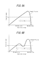
- FIGS. 9A and 9B are graphs illustrating secure detection of an operation voltage for maximizing power generation in the first embodiment
- FIGS. 10A to 10C are graphs illustrating various PV curves included in the rated PV curve in the first embodiment
- FIGS. 11A to 11C are graphs illustrating a determination method of a lower limit of a changing range with respect to a certain PV curve
- FIGS. 12A to 12C are graphs illustrating a determination method of the lower limit of the changing range with respect to another PV curve
- FIG. 13 is a graph illustrating an approximation straight line of the rated VI curve of the solar cell according to a second embodiment
- FIG. 14 is a graph illustrating an approximation straight line of the rated PV curve of the solar cell according to the second embodiment
- FIG. 15 is a graph illustrating an approximation straight line of the rated PI curve of the solar cell according to the second embodiment
- FIG. 16 is a graph illustrating an approximation straight line of the rated VI curve of the solar cell according to a third embodiment
- FIG. 17 is a graph illustrating an approximation straight line of the rated PV curve of the solar cell according to the third embodiment.
- FIG. 18 is a graph illustrating an approximation straight line of the rated PI curve of the solar cell according to the third embodiment.
- FIG. 1 is a functional block diagram illustrating a schematic configuration of the solar power generation system including the power generation control apparatus according to the present embodiment.
- solid lines connecting each functional block represent a power flow.
- broken lines connecting each functional block represent a flow of a control signal or transmitted information.
- a solar power generation system 10 is connected to a load apparatus 11 and a commercial system 12 .
- the solar power generation system 10 supplies AC power to the load apparatus 11 .
- the commercial system 12 supplies the shortage to the load apparatus 11 .
- the AC power supplied from the solar power generation system 10 is excessive over the demand of the load apparatus 11 , the excessive power is flown in reverse to the commercial system 12 for electric power selling.
- the solar power generation system 10 includes a solar cell 13 and a power generation control apparatus 14 .
- the solar cell 13 generates DC power by photoelectrically converting light incident on the solar panel.
- the power generation control apparatus 14 may convert a DC current output from the solar cell 13 into an AC current and supply the AC current to the load apparatus 11 and the commercial system 12 . Also, the power generation control apparatus 14 carries out MPPT control to the solar cell 13 so as to maximize the power generated by the solar cell 13 .
- the power generation control apparatus 14 includes an inverter 15 , a current and voltage sensor 16 , a timer 17 , a solar cell controller 18 , a method selector 19 , and a range determinator 20 .
- the inverter 15 converts the DC power generated by the solar cell 13 into the AC power.
- the current and voltage sensor 16 detects an operation current and an operation voltage of the solar cell 13 .
- the timer 17 counts the present time.
- the solar cell controller 18 controls the solar cell 13 to generate power by using a particular driving variable.
- the driving variable is at least one of the operation voltage and the operation current of the solar cell 13 .
- the method selector 19 determines one of the operation voltage and the operation current as the driving variable to be used to drive the solar cell 13 . Varying the driving variable changes the power generated by the solar cell 13 .
- the solar cell controller 18 also, executes first MPPT control or second MPPT control so as to maximize the power generated by the solar cell 13 .
- the solar cell controller 18 changes the driving variable in either one of a downward direction or an upward direction until the driving variable reaches a lower limit or an upper limit of a first range that is set or updated by the range determinator 20 .
- the solar cell controller 18 while changing the driving variable, calculates actual generated power of the solar cell 13 .
- the solar cell controller 18 when the driving variable reaches the lower limit or the upper limit of the first range, controls the solar cell 13 to generate power by using a driving variable that maximizes generated power during the change of the driving variable within the first range.
- the solar cell controller 18 changes the driving variable in a direction that increases the power generated by the solar cell 13 .
- the solar cell controller 18 while changing the driving variable, calculates the actual generated power of the solar cell 13 .
- the solar cell controller 18 when the actual generated power of the solar cell 13 turns to decrease, stops changing the driving variable and controls the solar cell 13 to generate power by using a driving variable immediately before the turning to decrease.
- the method selector 19 controls the solar cell controller 18 to execute either one of the first MPPT control and the second MPPT control.
- the first MPPT control includes downward direction MPPT control and upward direction MPPT control.
- the method selector 19 controls the solar cell controller 18 to execute the downward direction MPPT control in a downward direction period, the upward direction MPPT control in an upward direction period, and the second MPPT control in a second period.
- the method selector 19 determines the upward direction period and the downward direction period based on variables obtained in the upward direction MPPT control and the downward direction MPPT control, which are previously executed, respectively. Note that lower limits of the upward direction period and the downward direction period are determined to be longer than the second period that is preliminarily determined as a fixed value.
- the range determinator 20 determines the first range for changing the driving variable. Also, the range determinator 20 updates the first range during execution of the first MPPT control.
- the first MPPT control i.e., the downward direction MPPT control and the upward direction MPPT control will be described in detail.
- downward direction MPPT control the operation voltage serving as the driving variable is reduced.
- upward direction MPPT control the operation current serving as the driving variable is reduced, thereby increasing the operation voltage.
- the solar cell controller 18 calculates present generated power of the solar cell 13 .
- the solar cell controller 18 stores the present generated power and a corresponding operation voltage as maximum generated power and a maximum operation voltage, respectively.
- the range determinator 20 determines the lower limit of the first range for changing the operation voltage.
- the rated PV curve as illustrated in FIG. 2 , is a curve indicative of a relation between each rated operation voltage and the generated power. That is, the rated PV curve is a curve indicating a relation between each operation voltage and the maximum generated power.
- the range determinator 20 determines, as the lower limit of the first range, a smaller operation voltage between two operation voltages corresponding to the maximum generated power on the rated PV curve.
- the method selector 19 sets a unit change amount of the operation voltage to a first changing voltage ⁇ V 1 , which is a predetermined value.
- the solar cell controller 18 controls the solar cell 13 to generate power such that the operation voltage meets a value obtained by reducing the first changing voltage ⁇ V 1 from a present operation voltage.
- the solar cell controller 18 based on an actual operation voltage and the operation current of the solar cell 13 after the change in the operation voltage, calculates the actual generation power of the solar cell 13 .
- the solar cell controller 18 compares the actual generated power to the maximum generated power being stored.
- the solar cell controller 18 updates the maximum generated power being stored with the actual generated power and also updates the corresponding maximum operation voltage.
- the range determinator 20 based on thus updated maximum generated power and the rated PV curve, updates the lower limit of the first range of the operation voltage.
- the solar cell controller 18 nor the range determinator 20 updates the maximum generated power and the lower limit of the first range of the operation voltage, respectively.
- the solar cell controller 18 After the comparison of the actual generated power to the maximum generated power, the solar cell controller 18 once again controls the solar cell 13 to generate power such that the operation voltage meets the value obtained by reducing the first changing voltage ⁇ V 1 from the present operation voltage. In a manner similar to the control described above, the solar cell controller 18 calculates the actual generated power of the solar cell 13 . Further, the solar cell controller 18 compares the actual generated power to the maximum generated power being stored.
- the solar cell controller 18 thereafter repeats changing the operation voltage until the operation voltage reaches the lower limit of the first range.
- the solar cell controller 18 when the operation voltage reaches the lower limit of the first range, stops changing the operation voltage.
- the solar cell controller 18 detects the maximum operation voltage stored at the end of the change in the operation voltage as the operation voltage for maximizing the generated power of the solar cell 13 of the present condition.
- the solar cell controller 18 controls the solar cell 13 to generate power by using the maximum operation voltage.
- a downward direction period ⁇ T vd is calculated by substituting an open circuit voltage V oc of the solar cell 13 , a present operation voltage V pv , and a lower limit V nmin of the first range into the following formula (1).
- T base represents a predetermined base period that is set to be longer than the second period. Also, A is an invariable.
- the solar cell controller 18 calculates the present generated power of the solar cell 13 .
- the solar cell controller 18 stores the present generated power and an operation current corresponding thereto as the maximum generated power and the maximum operation current, respectively.
- the range determinator 20 determines the lower limit of the first range for changing the operation current.
- the rated PI curve is a curve indicative of a relation between each rated operation current and the generated power. Note that, by using a rated IV curve illustrated in FIG. 4 , the rated PV curve illustrated in FIG. 2 may be converted into the rated PI curve.
- the range determinator 20 determines, as the lower limit of the first range, a smaller operation current between two operation currents corresponding to the maximum generated power on the rated PI curve.
- the method selector 19 sets the unit change amount of the operation current during searching change to a first changing current ⁇ I 1 , which is a predetermined value.
- the solar cell controller 18 controls the solar cell 13 to generate power such that the operation current meets a value obtained by reducing the first changing current ⁇ I 1 from a present operation current.
- the operation voltage increases in inverse proportion to the operation current. In upward direction MPPT control, accordingly, decreasing the operation current serving as the driving variable increases the operation voltage.
- the lower limit of the first range of the operation current is equivalent to the upper limit of the range for changing the operation voltage.
- the solar cell controller 18 based on the actual operation voltage and an actual operation current of the solar cell 13 after the change in the operation current, calculates the actual generated power of the solar cell 13 .
- the solar cell controller 18 compares the actual generated power to the maximum generated power.
- the solar cell controller 18 updates the maximum generated power with the actual generated power and also updates the maximum operation current.
- the range determinator 20 based on the maximum generated power being updated and the rated PI curve, updates the lower limit of the first range of the operation current.
- the solar cell controller 18 nor the range determinator 20 updates the maximum generated power and the lower limit of a changing range of the operation current, respectively.
- the solar cell controller 18 After the comparison of the actual generated power to the maximum generated power, the solar cell controller 18 once again controls the solar cell 13 to generate power such that the operation current meets the value obtained by reducing the first changing current ⁇ I 1 from the present operation current. In a manner similar to the control described above, the solar cell controller 18 calculates the actual generated power of the solar cell 13 . Further, the solar cell controller 18 compares the actual generated power to the maximum generated power being stored.
- the solar cell controller 18 thereafter repeats changing the operation current until the operation current reaches the lower limit of the first range.
- the solar cell controller 18 when the operation current reaches the lower limit of the first range, stops changing the operation current.
- the solar cell controller 18 detects the maximum operation current stored at the end of the change in the operation current as the operation current for maximizing the generated power of the solar cell 13 of the present condition.
- the solar cell controller 18 controls the solar cell 13 to generate power by using the maximum operation current thus detected.
- the method selector 19 calculates the upward direction period before execution of next upward direction MPPT control.
- An upward direction period ⁇ T vu is calculated by substituting a short circuit current I sc of the solar cell 13 , a present operation current I pv , and a lower limit I nmin of the first range into the following formula (2).
- the method selector 19 controls the solar cell controller 18 to execute the upward direction MPPT control.
- the method selector 19 determines the operation voltage as the driving variable. Also, the method selector 19 sets the unit change amount of the operation voltage to a second changing voltage ⁇ V 2 , which is a predetermined value. The second changing voltage ⁇ V 2 is smaller than the first changing voltage ⁇ V 1 of the downward direction.
- the solar cell controller 18 increases or reduces the present operation voltage by the second changing voltage ⁇ V 2 and compares the power generated by the solar cell 13 before and after such a change. When the generated power after the change is larger, the solar cell controller 18 determines a present changing direction as a changing direction of the second MPPT control. When the generated power after the change is smaller, the solar cell controller 18 determines an inverse direction of the present changing direction as the changing direction of the second MPPT control.
- the solar cell controller 18 while changing the operation voltage, compares the actual generated power of the solar cell 13 before and after the change in the second changing voltage ⁇ V 2 .
- the solar cell controller 18 after the change of the operation voltage, changes the operation voltage until the generated power decreases.
- the solar cell controller 18 determines the operation voltage before the change as the operation voltage for maximizing the generated power.
- the solar cell controller 18 controls the solar cell 13 to generate power by using the operation voltage thus determined.
- the timing management operation starts when the power generation control apparatus 14 starts converting the DC current generated by the solar cell 13 into the AC current.
- the method selector 19 resets timing management time t, previous downward direction MPPT control execution time T pd , previous upward direction MPPT control execution time T pu , and previous second MPPT control execution time T p2 to zero. Also, the method selector 19 resets the downward direction period ⁇ T vd and the upward direction period ⁇ T vu to the base period T base . Note that the timing management time t, after being reset to 0, changes based on the present time counted by the timer 17 and thus indicates an elapsed time after the resetting. After the resetting, the process proceeds to step S 101 .
- step S 101 the method selector 19 determines whether the timing management time t has passed the downward direction period ⁇ T vd from the previous downward direction MPPT control execution time T pd .
- the process proceeds to step S 200 .
- the process proceeds to step S 104 .
- step S 200 the method selector 19 controls the solar cell controller 18 to execute the downward direction MPPT control. After the end of the downward direction MPPT control, the process proceeds to step S 102 .
- step S 102 the method selector 19 updates the downward direction MPPT control execution time T pd with the timing management time t. After the updating, the process proceeds to step S 103 .
- step S 103 the method selector 19 , based on the present operation voltage V pv of the downward direction MPPT control and the lower limit V nmin of the first range for changing the operation voltage, calculates the downward direction period ⁇ T vd . After the calculation of the downward direction period ⁇ T vd , the process returns to step S 101 .
- step S 104 the method selector 19 determines whether the timing management time t has passed the upward direction period ⁇ T vu from the previous upward direction MPPT control execution time T pu .
- the process proceeds to step S 300 .
- the process proceeds to step S 107 .
- step S 300 the method selector 19 controls the solar cell controller 18 to execute the upward direction MPPT control. After the upward direction MPPT control, the process proceeds to step S 105 .
- step S 105 the method selector 19 updates the upward direction MPPT control execution time T pu with the timing management time t. After the updating, the process proceeds to step S 106 .
- step S 106 the method selector 19 , based on the present operation current I pv , of the upward direction MPPT control and the lower limit I nmin of the first range for changing the operation current, calculates the upward direction period ⁇ T vu . After the calculation of the upward direction period ⁇ T vu , the process returns to step S 101 .
- step S 107 the method selector 19 determines whether the timing management time t has passed the second period ⁇ T 2 from the previous second MPPT control execution time T p2 .
- the process proceeds to step S 400 .
- the process returns to step S 101 .
- step S 400 the method selector 19 controls the solar cell controller 18 to execute the second MPPT control. After the second MPPT control, the process proceeds to step S 108 .
- step S 108 the method selector 19 updates the second MPPT control execution time T p2 with the timing management time t. After the updating, the process returns to step S 101 .
- the solar cell controller 18 When the subroutine of the downward direction MPPT control starts, the solar cell controller 18 , at step S 201 , resets a command voltage V n serving as a target value of the operation voltage to the present operation voltage V pv . Also, the solar cell controller 18 resets a maximum operation voltage V nmax to the present operation voltage V pv . Further, the solar cell controller 18 resets maximum generated power P nmax to the product of the present operation voltage V pv and the present operation current I pv . After the resetting, the process proceeds to step S 202 .
- step S 202 the solar cell controller 18 , based on the maximum generated power P nmax and the rated PV curve, calculates the lower limit V nmin of the first range of the operation voltage. After the calculation of the lower limit V nmin , the process proceeds to step S 203 .
- step S 203 the solar cell controller 18 updates the command voltage V n with a voltage obtained by subtracting the first changing voltage ⁇ V 1 from the present command voltage V n . After the updating of the command voltage V n , the process proceeds to step S 204 .
- step S 204 the solar cell controller 18 determines whether the command voltage V n is larger than the lower limit V nmin of the first range. When the command voltage V n is larger than the lower limit V nmin , the process proceeds to step S 205 . When the command voltage V n is equal to or smaller than the lower limit V nmin , the process proceeds to step S 208 .
- step S 205 the solar cell controller 18 controls the solar cell 13 such that the present operation voltage V pv meets the command voltage V n . After the control of the solar cell 13 , the process proceeds to step S 206 .
- the solar cell controller 18 determines whether the product of the present operation voltage V pv and the present operation current I pv is larger than the maximum generated power P nmax . When the product is equal to or smaller than the maximum generated power P nmax , the process returns to step S 203 . When the product is larger than the maximum generated power P nmax , the process proceeds to step S 207 .
- the solar cell controller 18 updates the maximum generated power P nmax with the product of the present operation voltage V pv and the present operation current I pv . Also, the solar cell controller 18 updates the maximum operation voltage V nmax with the present operation voltage V pv . After the updating, the process returns to step S 202 .
- step S 204 when the command voltage V n is equal to or smaller than the lower limit V nmin , the process proceeds to step S 208 .
- step S 208 the solar cell controller 18 controls the solar cell 13 such that the present operation voltage V pv meets the maximum operation voltage V nmax .
- the subroutine of the downward direction MPPT control is ended, and the process returns to step S 102 .
- the solar cell controller 18 When the subroutine of the upward direction MPPT control starts, the solar cell controller 18 , at step S 301 , resets a command current I n serving as a target value of the operation current to the present operation current I pv . Also, the solar cell controller 18 resets a maximum operation current I nmax to the present operation current I pv . Further, the solar cell controller 18 resets the maximum generated power P nmax to the product of the present operation voltage V pv and the present operation current I pv . After the resetting, the process proceeds to step S 302 .
- step S 302 the solar cell controller 18 , based on the maximum generated power P nmax and the rated PI curve, calculates the lower limit I nmin of the first range of the operation current. After the calculation of the lower limit I nmin , the process proceeds to step S 303 .
- step S 303 the solar cell controller 18 updates the command current I n with a current obtained by subtracting a first changing current ⁇ I 1 from the command current I n of the present. After the updating of the command current I n , the process proceeds to step S 304 .
- step S 304 the solar cell controller 18 determines whether the command current I n is larger than the lower limit I nmin of the changing range. When the command current I n is larger than the lower limit I nmin , the process proceeds to step S 305 . When the command current I n is equal to or smaller than the lower limit I nmin , the process proceeds to step S 308 .
- step S 305 the solar cell controller 18 controls the solar cell 13 such that the present operation current I pv meets the command current I n . After the control of the solar cell 13 , the process proceeds to step S 306 .
- step S 306 the solar cell controller 18 determines whether the product of the present operation voltage V pv and the present operation current I pv is larger than the maximum generated power P nmax .
- the process returns to step S 303 .
- the process proceeds to step S 307 .
- the solar cell controller 18 updates the maximum generated power P nmax with the product of the present operation voltage V pv and the present operation current I pv . Also, the solar cell controller 18 updates the maximum operation current I nmax with the present operation current I pv . After the updating, the process returns to step S 302 .
- step S 304 when the command current I n is equal to or smaller than the lower limit I nmin , the process proceeds to step S 308 .
- step S 308 the solar cell controller 18 controls the solar cell 13 such that the present operation current I pv meets the maximum operation current I nmax .
- the subroutine of the upward direction MPPT control is ended, and the process returns to step S 105 .
- the solar cell controller 18 When the subroutine of the second MPPT control starts, the solar cell controller 18 , at step S 401 , resets a direction coefficient V sgn for determining the changing direction of the operation voltage to ⁇ 1. Also, the solar cell controller 18 resets a previous generated power P n to the product of the present operation voltage V pv and the present operation current I pv . After the resetting, the process proceeds to step S 402 .
- step S 402 the solar cell controller 18 updates the command voltage V n with a voltage obtained by changing the second changing voltage ⁇ V 2 from the present command voltage V n in a direction corresponding to a sign of the direction coefficient V sng .
- the process proceeds to step S 403 .
- step S 403 the solar cell controller 18 controls the solar cell 13 such that the present operation voltage V pv meets the command voltage V n . After the control of the solar cell 13 , the process proceeds to step S 404 .
- step S 404 the solar cell controller 18 determines whether the product of the present operation voltage V pv and the present operation current I pv is smaller than the previous generated power P n .
- the process proceeds to step S 405 .
- the process proceeds to step S 406 , skipping the step S 405 .
- step S 405 the solar cell controller 18 inverts the sign of the direction coefficient V sgn . After the inversion, the process proceeds to step S 406 .
- step S 406 the solar cell controller 18 updates the previous generated power P n with the product of the present operation voltage V pv and the present operation current I pv . After the updating, the process proceeds to step S 407 .
- step S 407 and subsequent step S 408 similarly to step S 402 and step S 403 , respectively, the solar cell controller 18 updates the command voltage V n and controls the solar cell 13 such that the present operation voltage V pv meets the command voltage V n .
- step S 409 similarly to step S 404 , the solar cell controller 18 determines whether the product of the present operation voltage V pv and the present operation current I pv is smaller than the previous generated power P n .
- the process returns to step S 406 .
- the process proceeds to step S 410 .
- step S 410 the solar cell controller 18 updates the command voltage V n with a voltage obtained by changing the second changing voltage ⁇ V 2 from the present command voltage V n in a direction corresponding to an inverted sign of the direction coefficient V sgn .
- the process proceeds to step S 411 .
- step S 411 similarly to step S 403 , the solar cell controller 18 controls the solar cell 13 such that the present operation voltage V pv meets the command voltage V n .
- the subroutine of the second MTTP control is ended, and the process returns to step S 108 .
- the first MPPT control may achieve accurate detection of a maximum output point of the solar cell, that is, the operation voltage and the operation current that maximize the generated power. The following is a detailed description of such an effect.
- the PV curve indicative of the relation between the operation voltage of the solar cell 13 and the generated power is upwardly convex with a maximum value. Accordingly, a range of the operation voltage where the generated power exceeds present generated power P pv lies between a minimum value and a maximum value of an operation voltage coordinate on an intersection of a present PV curve and the present generated power P pv (see a sign “VR”). In other words, the operation voltage for maximizing the generation power falls within this range. Accordingly, the use of the present generated power P pv and the present PV curve allows reliable detection of the operation voltage for maximizing the generated power.
- the power generated by the solar cell 13 is influenced by, in addition to the operation voltage, conditions such as, for example, a solar radiation amount, temperature, and a shaded portion. Therefore, the PV curve differs based on each condition. As illustrated in FIGS. 10( a ) , 10 ( b ), and 10 ( c ), however, any PV curve is included between the rated PV curve and an operation voltage axis. Therefore, the range of the operation voltage determined by using the present generated power P pv and the present rated PV curve is included within the range of the operation voltage determined by using the present generated power P pv and the rated PV curve as described above.
- the present embodiment determines a changing range of the operation voltage by using the present generated power P pv and the rated PV curve, and thus is capable of reliably detecting the operation voltage for maximizing the generated power.
- the first range is updated when the present generated power is larger than the maximum generated power detected during the first MPPT control. Therefore, as described below, the change in the driving variable in an unnecessarily wide range may be prevented.
- the changing range of the searching change in a case where the relation between the operation voltage and the generated power when the solar cell 13 is in a certain state is indicated by the PV curve illustrated in FIG. 10( a ) will be described.
- the lower limit V nmin of the changing range is determined (see FIG. 11( a ) ).
- the present operation voltage V pv is reduced and the generated power increases
- the lower limit V nmin of the changing range is updated and increases to be higher than the previous lower limit (see FIG. 11( b ) ).
- the generated power is maximized, the updating of the lower limit V nmin of the changing range is stopped (see FIG. 11( c ) ). Therefore, with respect to the PV curve illustrated in FIG. 10( a ) , the searching change is executed within a range between V pv in FIG. 11( a ) and V nmin in FIG. 11( c ) .
- the changing range of the searching change in a case where the relation between the operation voltage and the generation power when the solar cell 13 is in another state is indicated by the PV curve illustrated in FIG. 10( c ) will be described.
- the lower limit V nmin of the changing range is determined (see FIG. 12( a ) ).
- the updating of the lower limit V nmin of the changing range is stopped, and the present operation voltage V pv is reduced until the generated power exceeds the first maximum value (see FIG. 12( b ) ).
- the updating of the lower limit V nmin of the changing range is resumed.
- the updating is stopped (see FIG. 12( c ) ).
- the searching change is executed within a range between V pv in FIG. 12( a ) and V nmin in FIG. 12( c ) .
- the changing range is set to be applicable to any PV curve, thereby preventing the driving variation from being changed in an unnecessarily wide range.
- the increase in the operation voltage is executed by adjusting the operation current. Therefore, as described below, the generated power may be maximized highly accurately.
- a rated PV curve in a range over the operation voltage for maximizing the generated power has a very large absolute value of gradient. Accordingly, the changing amount of the generated power per unit change amount of the operation voltage becomes large, leading to difficulty in fine adjustment of the generated power by increasing the operation voltage.
- the operation voltage is increased by decreasing the operation current. Therefore, the generated power may be finely adjusted, and thus the generated power may be maximized highly accurately.
- the execution period of the downward direction MPPT control and the execution period of the upward direction MPPT control may be determined separately. Optimum periods for those controls vary based on the changing range of the driving variable. Therefore, based on the changing range of the downward direction MPPT control and the changing range of the upward direction MPPT control, the optimum execution periods may be determined.
- the first MPPT control since the execution period of the first MPPT control is longer as the first range is narrower, the first MPPT control may be prevented from being executed at unnecessarily high frequency.
- the execution period of the first MPPT control is determined to be longer as the changing range is narrower, whereby the first MPPT control may be prevented from being executed at unnecessarily high frequency.
- the second MPPT control since the second MPPT control is executed for the period shorter than the first MPPT control, degradation of power generation efficiency due to the change in the driving variable may be suppressed.
- the first MPPT control may achieve reliable detection of the operation voltage or the operation current for maximizing the generated power.
- the second MPPT control takes a shorter time to maximize the generated power than the first MPPT control. According to the first embodiment, therefore, the first MPPT control is executed for a relatively long period, thereby suppressing the degradation of the power generation efficiency when another maximum value of the generation power becomes the maximum value.
- the second MPPT control is executed for a relatively short period, thereby suppressing changing of the driving variable in a relatively long period. As a result, the degradation of the power generation efficiency may be suppressed.
- the second embodiment is different from the first embodiment in terms of using, in place of the rated PV curve and the rated PI curve, approximation straight lines of the rated PV curve and the rated PI curve.
- the following is a description of the second embodiment focusing on points of difference thereof from the first embodiment. Note that units having the same functions and configurations as those of the first embodiment will be given the same reference numerals.
- a VI curve indicative of the operation current with respect to the operation voltage of the solar cell 13 may be approximated by the short circuit current I sc and the open circuit voltage V oc as illustrated in FIG. 13 .
- the rated PV curve is approximated by formulae (3) and (4) (see FIG. 14 ).
- the rated PI curve is approximated by formulae (5) and (6) (see FIG. 15 ).
- the solar cell controller 18 by using an approximation straight line of the rated PV curve and an approximation straight line of the rated PI curve, executes the downward direction MPPT control and the upward direction MPPT control.
- the first MPPT control without changing the driving variation in an unnecessarily wide range, may achieve accurate detection of the maximum output point of the solar cell, i.e., the operation voltage and the operation current for maximizing the generated power.
- the generated power may be maximized highly accurately.
- the execution period of the downward direction MPPT control and the execution period of the downward direction MPPT control may be determined separately.
- the first MPPT control may be prevented from being executed at unnecessarily high frequency.
- the second MPPT control is executed for a period shorter than the first MPPT control, the degradation of the power generation efficiency due to the change in the driving variable may be suppressed.
- the lower limit of the changing range may be calculated much more easily than the first embodiment. That is, based on an approximation straight line of the formula (3), provided that P nmax represents the maximum generated power during the searching change, the lower limit V nmin of the changing range of the operation voltage is calculated from formula (7). Also, based on an approximation curve of the formula (5), the lower limit I nmin of the changing range of the operation current is calculated from formula (8).
- V nmin P nmax I sc ( 7 )
- I nmin P nmax V oc ( 8 )
- the short circuit current I sc and the open circuit voltage V oc may be used. Therefore, there is no need for preliminarily detection, and the short circuit current I sc and the open circuit voltage V oc may be detected immediately before usage. Also, when the rated short circuit current I sc and the open circuit voltage V oc change due to, for example, aged deterioration of the solar cell 13 , updating may be easily carried out.
- the third embodiment is different from the first embodiment in terms of using, in place of the rated PV curve and the rated PI curve, the approximation curves of the rated PV curve and the rated PI curve.
- the following is a description of the third embodiment focusing on points of difference thereof from the first embodiment. Note that units having the same functions and configurations as those of the first embodiment will be given the same reference numerals.
- a portion of the VI curve indicative of the operation current with respect to the operation voltage of the solar cell 13 may be approximated by formula (9) that uses the short circuit current I sc and parallel resistance R sh of the solar cell 13 .
- VI curve may be approximated by formula (10) that uses the open circuit voltage V oc and series resistance R s of the solar cell 13 .
- V ⁇ R s ⁇ I+V oc (10)
- the rated PV curve is approximated by formulae (11) and (12) (see FIG. 17 ). Also, the rated PI curve is approximated by formulae (13) and (14) (see FIG. 18 ).
- the solar cell controller 18 by using the approximation curve of the rated PV curve and the approximation curve of the rated PI curve, executes the downward direction MPPT control and the upward direction MPPT control.
- the power generation control apparatus of the third embodiment may carry out the first MPPT control that, without changing the driving variable in an unnecessarily wide range, may achieve accurate detection of the maximum output point of the solar cell, i.e., the operation voltage and the operation current for maximizing the generation power.
- the generated power may be maximized highly accurately.
- the execution period of the downward direction MPPT control and the execution period of the upward direction MPPT control may be determined separately.
- the first MPPT control may be prevented from being executed at unnecessarily high frequency.
- the second MPPT control is executed for a period shorter than the first MPPT control, the degradation of the power generation efficiency due to the change in the driving variable may be suppressed.
- the lower limit of the changing range may be calculated more easily than the first embodiment. That is, based on the approximation curve of the formula (11), provided that P nmax represents the maximum generated power during the search changing, the lower limit V nmin of the changing range of the operation voltage is calculated from formula (15). Also, based on an approximation curve of the formula (13), the lower limit I nmin of the changing range of the operation current is calculated from formula (16).
- V nmin I sc ⁇ R sh 2 - ( I sc ⁇ R sh 2 ) 2 - P nmax ⁇ R sh ( 15 )
- I nmin V oc 2 ⁇ R s - ( V oc 2 ⁇ R s ) 2 - P nmax R s ( 16 )
- the rated PV curve is approximated by using the formula (3)
- the formula (17) may be used instead for the approximation.
- the formula (18) may be used instead for the approximation.
- C 1 an C 2 are invariables larger than 0 and equal to or smaller than 1.
Landscapes
- Engineering & Computer Science (AREA)
- Power Engineering (AREA)
- Physics & Mathematics (AREA)
- General Physics & Mathematics (AREA)
- Life Sciences & Earth Sciences (AREA)
- Sustainable Development (AREA)
- Sustainable Energy (AREA)
- Electromagnetism (AREA)
- Radar, Positioning & Navigation (AREA)
- Automation & Control Theory (AREA)
- Control Of Electrical Variables (AREA)
- Photovoltaic Devices (AREA)
- Supply And Distribution Of Alternating Current (AREA)
Abstract
Description
provided that P represents the generated power, V represents the operation voltage, Isc represents a short circuit current of the solar cell, and C1 represents a first invariable larger than 0 and equal to or smaller than 1.
provided that Pnmax represents the maximum generated power.
provided that P represents the generated power, I represents the operation current, Voc represents an open circuit voltage of the solar cell, and C2 represents a second invariable larger than 0 and equal to or smaller than 1.
provided that Pnmax represents the maximum generated power.
provided that P represents the generated power, V represents the operation voltage, Rsh represents parallel resistance of the solar cell, and Isc represents the short circuit current of the solar cell.
provided that Pnmax represents the maximum generated power.
provided that P represents the generated power, I represents the operation current, Rs represents series resistance of the solar cell, and Voc represents the open circuit voltage of the solar cell.
provided that Pnmax represents the maximum generated power.
[Formula 11]
P=I sc ×V (3)
V=V oc (4)
P=V oc ×I (5)
I=I sc (6)
[Formula 14]
V=−R s ×I+V oc (10)
- 10 power supply system
- 11 load apparatus
- 12 commercial system
- 13 solar cell
- 14 power generation control apparatus
- 15 inverter
- 26 current and voltage sensor
- 17 timer
- 18 solar cell controller
- 19 method selector
- 20 range determinator
Claims (14)
Applications Claiming Priority (3)
| Application Number | Priority Date | Filing Date | Title |
|---|---|---|---|
| JP2012-142490 | 2012-06-25 | ||
| JP2012142490A JP5903341B2 (en) | 2012-06-25 | 2012-06-25 | Power generation control device, solar power generation system, and power generation control method |
| PCT/JP2013/003955 WO2014002476A1 (en) | 2012-06-25 | 2013-06-25 | Power generation control apparatus, solar power system, and power generation control method |
Publications (2)
| Publication Number | Publication Date |
|---|---|
| US20150194925A1 US20150194925A1 (en) | 2015-07-09 |
| US9608561B2 true US9608561B2 (en) | 2017-03-28 |
Family
ID=49782668
Family Applications (1)
| Application Number | Title | Priority Date | Filing Date |
|---|---|---|---|
| US14/408,546 Expired - Fee Related US9608561B2 (en) | 2012-06-25 | 2013-06-25 | Power generation control apparatus, solar power generation system, and power generation control method |
Country Status (4)
| Country | Link |
|---|---|
| US (1) | US9608561B2 (en) |
| EP (1) | EP2866119A4 (en) |
| JP (1) | JP5903341B2 (en) |
| WO (1) | WO2014002476A1 (en) |
Families Citing this family (6)
| Publication number | Priority date | Publication date | Assignee | Title |
|---|---|---|---|---|
| JP6371062B2 (en) * | 2014-01-28 | 2018-08-08 | 株式会社デンソー | Power converter |
| JP6307334B2 (en) * | 2014-04-23 | 2018-04-04 | 大井電気株式会社 | Solar cell control device |
| KR101741924B1 (en) | 2015-11-18 | 2017-06-15 | (주)다한테크 | Method for control hybrid MPPT to mitigate partial shading effects in photovoltaic arrays |
| CN106953299B (en) * | 2017-04-18 | 2019-02-22 | 国网江苏省电力有限公司无锡供电分公司 | A Transformer Early Warning Method and System Based on Real-time Power Quality |
| CN108983864B (en) * | 2018-10-15 | 2020-06-30 | 西安许继电力电子技术有限公司 | Tracking method and tracking device for photovoltaic maximum power point |
| EP4250557A4 (en) | 2020-12-22 | 2024-02-07 | Huawei Digital Power Technologies Co., Ltd. | Photovoltaic power generation system, power control method and combiner box |
Citations (9)
| Publication number | Priority date | Publication date | Assignee | Title |
|---|---|---|---|---|
| EP0653692A2 (en) | 1993-11-16 | 1995-05-17 | Canon Kabushiki Kaisha | Method and apparatus for controlling the power of a battery power source |
| JPH09230952A (en) | 1996-02-28 | 1997-09-05 | Canon Inc | Solar cell power controller |
| US5869956A (en) | 1996-09-06 | 1999-02-09 | Canon Kabushiki Kaisha | Solar power generation apparatus and power control device therefor |
| JP2004295688A (en) | 2003-03-27 | 2004-10-21 | Kyocera Corp | Solar power generator |
| JP2008176474A (en) | 2007-01-17 | 2008-07-31 | Tokyo Metropolitan Univ | Solar power system |
| EP2360546A1 (en) | 2010-02-24 | 2011-08-24 | SMA Solar Technology AG | Method for determining a point of maximum performance of photovoltaic generators |
| US20120013288A1 (en) | 2010-07-19 | 2012-01-19 | Samsung Electro-Mechanics Co., Ltd. | Solar cell system |
| WO2012020103A2 (en) | 2010-08-12 | 2012-02-16 | Sma Solar Technology Ag | Method for operation of a photovoltaic generator at an operating point of maximum power |
| US20120242152A1 (en) * | 2011-03-23 | 2012-09-27 | Abb Research Ltd | Method for searching global maximum power point |
-
2012
- 2012-06-25 JP JP2012142490A patent/JP5903341B2/en not_active Expired - Fee Related
-
2013
- 2013-06-25 WO PCT/JP2013/003955 patent/WO2014002476A1/en not_active Ceased
- 2013-06-25 US US14/408,546 patent/US9608561B2/en not_active Expired - Fee Related
- 2013-06-25 EP EP13810677.8A patent/EP2866119A4/en not_active Withdrawn
Patent Citations (12)
| Publication number | Priority date | Publication date | Assignee | Title |
|---|---|---|---|---|
| EP0653692A2 (en) | 1993-11-16 | 1995-05-17 | Canon Kabushiki Kaisha | Method and apparatus for controlling the power of a battery power source |
| JPH09230952A (en) | 1996-02-28 | 1997-09-05 | Canon Inc | Solar cell power controller |
| US5869956A (en) | 1996-09-06 | 1999-02-09 | Canon Kabushiki Kaisha | Solar power generation apparatus and power control device therefor |
| JP2004295688A (en) | 2003-03-27 | 2004-10-21 | Kyocera Corp | Solar power generator |
| JP2008176474A (en) | 2007-01-17 | 2008-07-31 | Tokyo Metropolitan Univ | Solar power system |
| EP2360546A1 (en) | 2010-02-24 | 2011-08-24 | SMA Solar Technology AG | Method for determining a point of maximum performance of photovoltaic generators |
| US20130027020A1 (en) | 2010-02-24 | 2013-01-31 | Sma Solar Technology Ag | Method for determining a maximum power point of photovoltaic generators |
| US9235226B2 (en) | 2010-02-24 | 2016-01-12 | Sma Solar Technology Ag | Method for determining a maximum power point of photovoltaic generators |
| US20120013288A1 (en) | 2010-07-19 | 2012-01-19 | Samsung Electro-Mechanics Co., Ltd. | Solar cell system |
| JP2012027913A (en) | 2010-07-19 | 2012-02-09 | Samsung Electro-Mechanics Co Ltd | Solar battery system |
| WO2012020103A2 (en) | 2010-08-12 | 2012-02-16 | Sma Solar Technology Ag | Method for operation of a photovoltaic generator at an operating point of maximum power |
| US20120242152A1 (en) * | 2011-03-23 | 2012-09-27 | Abb Research Ltd | Method for searching global maximum power point |
Non-Patent Citations (5)
| Title |
|---|
| Esram T et al: "Comparison of Photovoltaic Array Maximum Power Point Tracking Techniques", IEEE Transactions on Energy Conversion, IEEE Service Center, Piscataway, NJ, US, vol. 22, No. 2, Jun. 1, 2007 (Jun. 1, 2007), pp. 439-449, XP011184738, ISSN: 0885-8969, DOI: 10.1109/TEC.2006.874230. |
| Extended European Search Report dated Apr. 7, 2016 issued by the European Patent Office for Counterpart European Application No. EP 13 810 677.8. |
| International Search Report; PCT/JP2013/003955; Jul. 23, 2013. |
| T. ESRAM ; P.L. CHAPMAN: "Comparison of Photovoltaic Array Maximum Power Point Tracking Techniques", IEEE TRANSACTIONS ON ENERGY CONVERSION., IEEE SERVICE CENTER, PISCATAWAY, NJ., US, vol. 22, no. 2, 1 June 2007 (2007-06-01), US, pages 439 - 449, XP011184738, ISSN: 0885-8969, DOI: 10.1109/TEC.2006.874230 |
| Written Opinion of the International Searching Authority; PCT/JP2013/003955; Jul. 23, 2013; with concise explanation. |
Also Published As
| Publication number | Publication date |
|---|---|
| US20150194925A1 (en) | 2015-07-09 |
| JP5903341B2 (en) | 2016-04-13 |
| JP2014006747A (en) | 2014-01-16 |
| WO2014002476A1 (en) | 2014-01-03 |
| EP2866119A4 (en) | 2016-05-11 |
| EP2866119A1 (en) | 2015-04-29 |
Similar Documents
| Publication | Publication Date | Title |
|---|---|---|
| US9608561B2 (en) | Power generation control apparatus, solar power generation system, and power generation control method | |
| JP6007526B2 (en) | CHARGE POWER CONTROL DEVICE, CHARGE POWER CONTROL METHOD, PROGRAM, AND SOLAR POWER GENERATION SYSTEM | |
| US9337682B2 (en) | Charging control device, solar power generation system and charging control method | |
| KR100908156B1 (en) | Solar maximum power tracking device and method | |
| JP5459634B2 (en) | Maximum power point tracking method and apparatus in power conversion based on double feedback loop and power ripple | |
| US8860358B2 (en) | Method for operation of a photovoltaic generator at an operating point of maximum power | |
| TWI425174B (en) | The Sun can generate system | |
| US8450883B2 (en) | Maximum power point tracking control apparatus for solar battery | |
| US20130328406A1 (en) | Control system for solar power conversion unit, control method for the unit, and solar power generation system | |
| US9698710B2 (en) | Solar energy utilization system | |
| US20120326649A1 (en) | Systems and Methods for Operating a Solar Direct Pump | |
| JP6480198B2 (en) | Storage battery system and photovoltaic power generation system having the same | |
| KR102087063B1 (en) | Method and apparatus for improved burst mode during power conversion | |
| JP2010231456A (en) | Power system | |
| CN107172885A (en) | Maximum power point tracking device and evaluation method of solar cell module | |
| JP2018143038A (en) | Photovoltaic power generation system and power generation control program | |
| KR101382946B1 (en) | Photovoltaic power generation system and control method thereof | |
| JP6029540B2 (en) | Solar cell control device and solar cell control method | |
| JP2017085762A (en) | Solar power generation control device and control method therefor | |
| KR20160104331A (en) | Dc-dc converter of photovoltaics system using time delay estimation and control method thereof | |
| JP2024139298A (en) | Power Conversion Equipment | |
| JP2024139294A (en) | Power Conversion Equipment | |
| WO2018159383A1 (en) | Power conversion control device, power generation system, and power conversion control method |
Legal Events
| Date | Code | Title | Description |
|---|---|---|---|
| AS | Assignment |
Owner name: KYOCERA CORPORATION, JAPAN Free format text: ASSIGNMENT OF ASSIGNORS INTEREST;ASSIGNOR:GOTO, RYO;REEL/FRAME:034522/0371 Effective date: 20141120 |
|
| STCF | Information on status: patent grant |
Free format text: PATENTED CASE |
|
| MAFP | Maintenance fee payment |
Free format text: PAYMENT OF MAINTENANCE FEE, 4TH YEAR, LARGE ENTITY (ORIGINAL EVENT CODE: M1551); ENTITY STATUS OF PATENT OWNER: LARGE ENTITY Year of fee payment: 4 |
|
| FEPP | Fee payment procedure |
Free format text: MAINTENANCE FEE REMINDER MAILED (ORIGINAL EVENT CODE: REM.); ENTITY STATUS OF PATENT OWNER: LARGE ENTITY |
|
| LAPS | Lapse for failure to pay maintenance fees |
Free format text: PATENT EXPIRED FOR FAILURE TO PAY MAINTENANCE FEES (ORIGINAL EVENT CODE: EXP.); ENTITY STATUS OF PATENT OWNER: LARGE ENTITY |
|
| STCH | Information on status: patent discontinuation |
Free format text: PATENT EXPIRED DUE TO NONPAYMENT OF MAINTENANCE FEES UNDER 37 CFR 1.362 |
|
| FP | Lapsed due to failure to pay maintenance fee |
Effective date: 20250328 |