US960403A - Propeller. - Google Patents
Propeller. Download PDFInfo
- Publication number
- US960403A US960403A US51392609A US1909513926A US960403A US 960403 A US960403 A US 960403A US 51392609 A US51392609 A US 51392609A US 1909513926 A US1909513926 A US 1909513926A US 960403 A US960403 A US 960403A
- Authority
- US
- United States
- Prior art keywords
- blade
- drum
- driving member
- blades
- length
- Prior art date
- Legal status (The legal status is an assumption and is not a legal conclusion. Google has not performed a legal analysis and makes no representation as to the accuracy of the status listed.)
- Expired - Lifetime
Links
- 238000010276 construction Methods 0.000 description 7
- 230000004048 modification Effects 0.000 description 3
- 238000012986 modification Methods 0.000 description 3
- 238000013459 approach Methods 0.000 description 1
- 230000003247 decreasing effect Effects 0.000 description 1
- 239000004744 fabric Substances 0.000 description 1
- 239000000463 material Substances 0.000 description 1
- 230000000979 retarding effect Effects 0.000 description 1
Images


Classifications
-
- B—PERFORMING OPERATIONS; TRANSPORTING
- B63—SHIPS OR OTHER WATERBORNE VESSELS; RELATED EQUIPMENT
- B63H—MARINE PROPULSION OR STEERING
- B63H1/00—Propulsive elements directly acting on water
- B63H1/02—Propulsive elements directly acting on water of rotary type
- B63H1/04—Propulsive elements directly acting on water of rotary type with rotation axis substantially at right angles to propulsive direction
- B63H1/06—Propulsive elements directly acting on water of rotary type with rotation axis substantially at right angles to propulsive direction with adjustable vanes or blades
- B63H1/08—Propulsive elements directly acting on water of rotary type with rotation axis substantially at right angles to propulsive direction with adjustable vanes or blades with cyclic adjustment
Definitions
- FIG 6 WITNESSESI g a) AZQmJNVI-INTOR d /a vm 6 is ANDREW a WWW CD woro-uwauuwzns vmsmemr: n r:
- the invention described herein relates to certain improvements in propellers especially of that class or kind which when in operation are entirely submerged in or surrounded by the element through which the vessel is to be driven, and the blade or blades at the time of maximum efiiciency move in a direction opposite that of the vessel, and the exposed area of the blade has an etliciency directly proportional to the rate of movement.
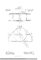
- Figure l is a perspective view of the driving member and a blade movably mounted therein;
- Fig. :2 is a top plan view of the driving member having a blade mounted therein and showing the track or guide for shifting the blade;
- Fig. 3 is a sectional elevation in a plane indicated by the line llllll Fig. 3;
- Figs. 4 and 5 are side and plan views respectively of a blade,
- Fig. 6 is a side elevation of the modification of the blade when two or more are employed,
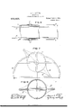
- Fig. 7 is a top plan view illustrating a modification of the driving member and blade;
- Fig. 8 is a. sectional elevation in the plane of the blade in Fig. 7;
- Fig. 9 is a sectional plan of the driving member shown in Figs. 7 and 8
- Fig. 10 is a plan view of the further modification of my improvement
- Fig. 11 is a sectional elevation on a plane indicated by the line XI XI Fig. 10.
- the driven member 1 is preferably made in the form of a drum provided with trunnions 2, and driven by any suitable means, applied to one of the trunnions.
- One, two or more blades 3 are mounted in suitable guides in the drum, which has diametrically arranged slots to permit or the alternate ynrojection of the ends of the blade beyond the drum.
- a convenient construction for that purpose consists of one or more tracks or curved guides adapted to engage the blades or projections therefrom, so that as the driving member and blade are rotated, the latter will be caused to move longitudinally one end moving out of the drum while the other end will move into the drum. Assuming that the driving member or drum and the blade are moving in the direction or the arrows in Fig. 2, the projecting end a. of the blade will remain projecting its greatest limit, until it reaches the entrance end of the portion 4. of the tracks.
- the blade As the end a of the blade moves along this portion of the track the blade will be moved longitudinally the portion a moving into the driving member or drum, and the opposite portion moving out of the drum.
- the portion l of the track gradually merges into the portion 5, which is concentric with the drum and so arranged that when one end of the blade moves along this portion of the track, it will be within the drum or prac tically so, while the opposite end of the blade projects the maximum distance from It will be observed that the rear end Z) of the concentric portion 5 of the track is diametrically opposite the entrance end of the portion A.
- the portion 6 of the track is employed for shifting the blade when the direction of rotation is reversed.
- the blade attains its greatest extension as it approaches that portion of the arc of its movement nearly parallel with the direction of movement of the vessel, and when the projecting portion will operate most efliciently.
- the blade is moved imvardly, and at about the time a portion of the blade begins to move in a direction opposite to the direction of movement of the vessel, such portion is inclosed in the drum and will not have any retarding action on the drum or on the vessel and practically the entire power applied to the drum and blade is utilized in moving the eflicient portion of the blade.
- the blades When used for air ships or flying ma-' ment of the blades, thereby forming cells for the reception of gas or gas containing bags.
- the blades can be made in the form of rectangular frames to which cloth or other suitable material can be attached.
- truss rods 8 are attached to the ends of the frame and are passed over struts 9 braced against the transverse bar or member of the frame of the blade.
- the drum should have a bearing on the blade for a distance not less than two thirds of the length of the blade, as shown in Figs. 1, 2 and 3. Hence in large propellers a large drum would be necessary.
- Figs. 7, 8 and 9 is shown a construction avoiding the use of large drums and at the same time insuring a longer bearing of the drum or driving member on the exposed portions of the blade.
- the drum is provided with bracing arms 10 extending from the periphery of the drum parallel with the line of movement of the blades. As will be seen in Fig. 7 these arms are made so as to have a broad bearing on the drum, but are quite narrow in a direction transverse of the blades so that they will present practically no resistance to the rotation of the drum.
- the drum or driving member can be made of a diameter or length equal to or less than half the length of the blade and the arms can be made of a length equal to or greater than half the length of the exposed portion of the blade.
- the proportions herein stated may be varied widely without departing from the spirit of the invention.
- Figs. 10 and 11 a construction in which a relatively small driving member is employed and the brace for the extended portion of the blade is made movable.
- the blade 3 is movably mounted in a casing or frame 11 which in turn is movably mounted in the driving member or drum.
- the casing or frame 11 is preferably made of a length about equal to three times the radius of the drum and the blade of a length about equal to twice the diameter of the drum.
- Fig. 6 a construction of blade adapted for use where two or more blades are mounted in the driving member or drum.
- the blades are recessed on one edge and reversed in position, so that the narrow portion of one blade will extend into the recess of the other blade. When three blades are used, one of them will be recessed on both edges.
- a propeller having in combination a rotating driving member, a blade movably mounted in the driving member, and of a length such that when one end of the blade is in or nearly in the driving member the opposite end will project a substantial distance outside of the driving member, braces on the driving member adapted to form lateral supports for the projecting portion of the blade, and means for reciprocating the blade.
- a propeller having in combination a rotating driving member, a blade normally mounted in the driving member and of a length such that when one end of the blade is in or nearly in the driving member the opposite end will project a substantial distance outside of the driving member, braces movably mounted 011 the driving member adapted to form lateral supports for the projecting portion of the blade, and means for reciprocating the blade.
- a propeller having in combination a diametrically slotted drum, a blade having a length greaterthan the diameter of the drum, and a curved track for shifting the blade having a portion beginning with a curvature corresponding to the are described by the outer end of the projecting portion of the blade and continuing with gradually decreasing radius, and a portion formed in a radius slightly greater than the radius of the drum extending from or approximately from the point where the exposed portion of the blade begins to move in a direction I with buoyancy chambers on opposite sides opposite to the direction of movement of the of the path of movement of the blade. vessel. In testimony whereof, I have hereunto set at.
Landscapes
- Chemical & Material Sciences (AREA)
- Engineering & Computer Science (AREA)
- Combustion & Propulsion (AREA)
- Mechanical Engineering (AREA)
- Ocean & Marine Engineering (AREA)
- Structures Of Non-Positive Displacement Pumps (AREA)
Description
E. A. RICHTER.
PROPELLER.
APPLICATION FILED AUG.21,1909.
Patented June 7, 1910.
4 SHEETS-BHEET l FHSA- 3 FIG 6 WITNESSESI g a) AZQmJNVI-INTOR d /a vm 6 is ANDREW a WWW CD woro-uwauuwzns vmsmemr: n r:
E. A. RICHTER.
PROPELLBR.
APPLICATION FILED AUG.21,1909.
Patented June '7, 1910.
4 SHEETSSHEET Z.
INVENTOR E. A: RICHTER.
PROPBLLER.
APPLICATION FILED AUG. 21, 1909.
Patented June '7, 1910.
SHEETS-SHEET 3.
FEE 7 INVENTOH Atty ANOREW 9. Guam co FNOTO-UTHOGRAPNERS. WASMNGTUN, D47.
E. A. RICHTER.
PROPELLER,
APPLICATION FILED AUG.21,1909.
960,403, Patented June '7, 1910.
4 SHEETS-SHEET 4. 1 2 F! s a 1 \FNESFESI v INVENTOR 7 .W 65w) ,flwlzz, ww az MIDREW B GRAHAM CO PWTDLITMOGIAPMIS WASHINGTON, nv c UNITED STATES PATENT ()FFIGE.
EDWARD A. RICHTER, OF PITTSBURG, PENNSYLVANIA.
PROPELLEB.
To all whom it may concern:
Be it known that I, EDWARD A. RICHTER, residing at Pittsburg, in the county of Allegheny and State of Pennsylvania, a citizen of the United States, have invented or discovered certain new and useful Improvements in Propellers, of which improvement the following is a specification.
The invention described herein relates to certain improvements in propellers especially of that class or kind which when in operation are entirely submerged in or surrounded by the element through which the vessel is to be driven, and the blade or blades at the time of maximum efiiciency move in a direction opposite that of the vessel, and the exposed area of the blade has an etliciency directly proportional to the rate of movement.
The invention is hereinafter more fully described and claimed.
In the accompanying drawings forming a part of this specification Figure l is a perspective view of the driving member and a blade movably mounted therein; Fig. :2 is a top plan view of the driving member having a blade mounted therein and showing the track or guide for shifting the blade; Fig. 3 is a sectional elevation in a plane indicated by the line llllll Fig. 3; Figs. 4 and 5 are side and plan views respectively of a blade, Fig. 6 is a side elevation of the modification of the blade when two or more are employed, Fig. 7 is a top plan view illustrating a modification of the driving member and blade; Fig. 8 is a. sectional elevation in the plane of the blade in Fig. 7; Fig. 9 is a sectional plan of the driving member shown in Figs. 7 and 8, Fig. 10 is a plan view of the further modification of my improvement, and Fig. 11 is a sectional elevation on a plane indicated by the line XI XI Fig. 10.
In the practice of my invention the driven member 1 is preferably made in the form of a drum provided with trunnions 2, and driven by any suitable means, applied to one of the trunnions. One, two or more blades 3 are mounted in suitable guides in the drum, which has diametrically arranged slots to permit or the alternate ynrojection of the ends of the blade beyond the drum.
Specification of Letters Patent.
Application filed August 21, 1909.
' the driving member.
Patented June *7, 1910.
Serial No. 513,926.
As it is one of the objects of the invention to utilize the end portions of the blade or blades alternately as propelling members, provision is made for imparting a reciprocating movement thereto. A convenient construction for that purpose consists of one or more tracks or curved guides adapted to engage the blades or projections therefrom, so that as the driving member and blade are rotated, the latter will be caused to move longitudinally one end moving out of the drum while the other end will move into the drum. Assuming that the driving member or drum and the blade are moving in the direction or the arrows in Fig. 2, the projecting end a. of the blade will remain projecting its greatest limit, until it reaches the entrance end of the portion 4. of the tracks. As the end a of the blade moves along this portion of the track the blade will be moved longitudinally the portion a moving into the driving member or drum, and the opposite portion moving out of the drum. The portion l of the track gradually merges into the portion 5, which is concentric with the drum and so arranged that when one end of the blade moves along this portion of the track, it will be within the drum or prac tically so, while the opposite end of the blade projects the maximum distance from It will be observed that the rear end Z) of the concentric portion 5 of the track is diametrically opposite the entrance end of the portion A. The portion 6 of the track is employed for shifting the blade when the direction of rotation is reversed.
it is characteristic of my improvement, that the blade attains its greatest extension as it approaches that portion of the arc of its movement nearly parallel with the direction of movement of the vessel, and when the projecting portion will operate most efliciently. hen such portion of the blade attains a position at right angles to the direction of movement of the vessel, where its etficiency rapidly diminishes, the blade is moved imvardly, and at about the time a portion of the blade begins to move in a direction opposite to the direction of movement of the vessel, such portion is inclosed in the drum and will not have any retarding action on the drum or on the vessel and practically the entire power applied to the drum and blade is utilized in moving the eflicient portion of the blade.
When used for air ships or flying ma-' ment of the blades, thereby forming cells for the reception of gas or gas containing bags. The blades can be made in the form of rectangular frames to which cloth or other suitable material can be attached. In order to render the blades transversely rigid, truss rods 8 are attached to the ends of the frame and are passed over struts 9 braced against the transverse bar or member of the frame of the blade.
For an efficient application of driving power to the blade, the drum should have a bearing on the blade for a distance not less than two thirds of the length of the blade, as shown in Figs. 1, 2 and 3. Hence in large propellers a large drum would be necessary.
In Figs. 7, 8 and 9 is shown a construction avoiding the use of large drums and at the same time insuring a longer bearing of the drum or driving member on the exposed portions of the blade. The drum is provided with bracing arms 10 extending from the periphery of the drum parallel with the line of movement of the blades. As will be seen in Fig. 7 these arms are made so as to have a broad bearing on the drum, but are quite narrow in a direction transverse of the blades so that they will present practically no resistance to the rotation of the drum. In such a construction the drum or driving member can be made of a diameter or length equal to or less than half the length of the blade and the arms can be made of a length equal to or greater than half the length of the exposed portion of the blade. The proportions herein stated may be varied widely without departing from the spirit of the invention.
In Figs. 10 and 11 is shown a construction in which a relatively small driving member is employed and the brace for the extended portion of the blade is made movable. The blade 3 is movably mounted in a casing or frame 11 which in turn is movably mounted in the driving member or drum. In this construction the casing or frame 11 is preferably made of a length about equal to three times the radius of the drum and the blade of a length about equal to twice the diameter of the drum. When so proportioned the casing or frame will when fully shifted in one direction, project about one third of its length beyond the periphery of the drum and the blade when fully shifted in the same direction will project about one fourth of its length beyond the casing or frame. While the shifting of the casing or frame may be effected by the blade, the latter being forced inwardly until its end is flush with the end of the casing or frame, which will thereafter move in with the blade, it is preferred to employ independent tracks 4? and 6 for the frame or casing. These tracks are preferably so constructed to engage the frame at or about the same time that the blade engages its track. In this construction there will not be any projection of the blade or the bracing casing or frame beyond that portion of the periphery of the drum moving in the same direction as the vessel.
In Fig. 6 is shown a construction of blade adapted for use where two or more blades are mounted in the driving member or drum. The blades are recessed on one edge and reversed in position, so that the narrow portion of one blade will extend into the recess of the other blade. When three blades are used, one of them will be recessed on both edges.
I claim herein as my invention:
1. A propeller having in combination a rotating driving member, a blade movably mounted in the driving member, and of a length such that when one end of the blade is in or nearly in the driving member the opposite end will project a substantial distance outside of the driving member, braces on the driving member adapted to form lateral supports for the projecting portion of the blade, and means for reciprocating the blade.
2. A propeller having in combination a rotating driving member, a blade normally mounted in the driving member and of a length such that when one end of the blade is in or nearly in the driving member the opposite end will project a substantial distance outside of the driving member, braces movably mounted 011 the driving member adapted to form lateral supports for the projecting portion of the blade, and means for reciprocating the blade.
- 3. A propeller having in combination a diametrically slotted drum, a blade having a length greaterthan the diameter of the drum, anda curved track for shifting the blade having a portion beginning with a curvature corresponding to the are described by the outer end of the projecting portion of the blade and continuing with gradually decreasing radius, and a portion formed in a radius slightly greater than the radius of the drum extending from or approximately from the point where the exposed portion of the blade begins to move in a direction I with buoyancy chambers on opposite sides opposite to the direction of movement of the of the path of movement of the blade. vessel. In testimony whereof, I have hereunto set at. A propeller having in combination a my hand.
EDXVARD A. RICHTER.
rotating drum, having a diametrically slotted periphery a blade of a length greater than the diameter of the drum, and means for shifting the blade, the drum being provided Witnesses SUE B. FRITZ, FRANCIS J. TOMASSON.
Priority Applications (1)
| Application Number | Priority Date | Filing Date | Title |
|---|---|---|---|
| US51392609A US960403A (en) | 1909-08-21 | 1909-08-21 | Propeller. |
Applications Claiming Priority (1)
| Application Number | Priority Date | Filing Date | Title |
|---|---|---|---|
| US51392609A US960403A (en) | 1909-08-21 | 1909-08-21 | Propeller. |
Publications (1)
| Publication Number | Publication Date |
|---|---|
| US960403A true US960403A (en) | 1910-06-07 |
Family
ID=3028801
Family Applications (1)
| Application Number | Title | Priority Date | Filing Date |
|---|---|---|---|
| US51392609A Expired - Lifetime US960403A (en) | 1909-08-21 | 1909-08-21 | Propeller. |
Country Status (1)
| Country | Link |
|---|---|
| US (1) | US960403A (en) |
Cited By (3)
| Publication number | Priority date | Publication date | Assignee | Title |
|---|---|---|---|---|
| US4519742A (en) * | 1981-04-02 | 1985-05-28 | Arend Van Buytene | Apparatus for utilizing the energy present in flowing water |
| DE102004041791A1 (en) * | 2004-02-28 | 2005-09-22 | BÖHME, Frank | Blade wheel with moving blades used as a ship's propulsion comprises rudder blades, a control ring, and water inlet and outlet channels |
| EP1798368A2 (en) | 2005-12-16 | 2007-06-20 | Sclumberger Technology B.V. | Side-wall probe assembly |
-
1909
- 1909-08-21 US US51392609A patent/US960403A/en not_active Expired - Lifetime
Cited By (3)
| Publication number | Priority date | Publication date | Assignee | Title |
|---|---|---|---|---|
| US4519742A (en) * | 1981-04-02 | 1985-05-28 | Arend Van Buytene | Apparatus for utilizing the energy present in flowing water |
| DE102004041791A1 (en) * | 2004-02-28 | 2005-09-22 | BÖHME, Frank | Blade wheel with moving blades used as a ship's propulsion comprises rudder blades, a control ring, and water inlet and outlet channels |
| EP1798368A2 (en) | 2005-12-16 | 2007-06-20 | Sclumberger Technology B.V. | Side-wall probe assembly |
Similar Documents
| Publication | Publication Date | Title |
|---|---|---|
| US4102293A (en) | Device for propelling ships | |
| US3307358A (en) | Device for propelling or pumping a fluid and application thereof to the propulsion of ships | |
| US960403A (en) | Propeller. | |
| US861997A (en) | Wave-motor. | |
| US2611321A (en) | Vessel and fluid propelling device | |
| US4529A (en) | Improvement in propellers for vessels | |
| FR2278565A1 (en) | Flap type marine propulsion system - has flaps operated by alternative mechanisms to give sinusoidal or cycloidal motion | |
| US1937907A (en) | Boat propelling means | |
| US427842A (en) | Submerged folding oar or paddle | |
| US1093693A (en) | Propulsion of vessels on and immersed in water. | |
| US314A (en) | Improvement in the manner of constructing and working paddles to be used as ice-breakers | |
| US1540257A (en) | dourif | |
| US1086274A (en) | Propeller for ships. | |
| US534737A (en) | Oscillating propeller | |
| US6914A (en) | Propeller | |
| US638211A (en) | Means for propelling and steering vessels. | |
| GB191004560A (en) | Improvements in Aeronautical Propellers. | |
| US1327975A (en) | Propulsion of air and other gases or fluids | |
| US9763A (en) | Improvement in propellers | |
| US1441361A (en) | Current motor | |
| US844372A (en) | Life-boat. | |
| US1429815A (en) | Power-transmission mechanism | |
| US634574A (en) | Propeller for vessels. | |
| US3424A (en) | Improvement in propelling canal an d other boats | |
| US966491A (en) | Propeller. |