US9601402B2 - Package apparatus and manufacturing method thereof - Google Patents
Package apparatus and manufacturing method thereof Download PDFInfo
- Publication number
- US9601402B2 US9601402B2 US14/505,973 US201414505973A US9601402B2 US 9601402 B2 US9601402 B2 US 9601402B2 US 201414505973 A US201414505973 A US 201414505973A US 9601402 B2 US9601402 B2 US 9601402B2
- Authority
- US
- United States
- Prior art keywords
- layer
- wiring layer
- molding compound
- forming
- dielectric material
- Prior art date
- Legal status (The legal status is an assumption and is not a legal conclusion. Google has not performed a legal analysis and makes no representation as to the accuracy of the status listed.)
- Active, expires
Links
Images


Classifications
-
- H—ELECTRICITY
- H10—SEMICONDUCTOR DEVICES; ELECTRIC SOLID-STATE DEVICES NOT OTHERWISE PROVIDED FOR
- H10W—GENERIC PACKAGES, INTERCONNECTIONS, CONNECTORS OR OTHER CONSTRUCTIONAL DETAILS OF DEVICES COVERED BY CLASS H10
- H10W74/00—Encapsulations, e.g. protective coatings
- H10W74/10—Encapsulations, e.g. protective coatings characterised by their shape or disposition
- H10W74/111—Encapsulations, e.g. protective coatings characterised by their shape or disposition the semiconductor body being completely enclosed
- H10W74/114—Encapsulations, e.g. protective coatings characterised by their shape or disposition the semiconductor body being completely enclosed by a substrate and the encapsulations
- H10W74/117—Encapsulations, e.g. protective coatings characterised by their shape or disposition the semiconductor body being completely enclosed by a substrate and the encapsulations the substrate having spherical bumps for external connection
-
- H01L23/3128—
-
- H01L21/561—
-
- H01L21/565—
-
- H01L23/5389—
-
- H01L25/0657—
-
- H—ELECTRICITY
- H10—SEMICONDUCTOR DEVICES; ELECTRIC SOLID-STATE DEVICES NOT OTHERWISE PROVIDED FOR
- H10W—GENERIC PACKAGES, INTERCONNECTIONS, CONNECTORS OR OTHER CONSTRUCTIONAL DETAILS OF DEVICES COVERED BY CLASS H10
- H10W70/00—Package substrates; Interposers; Redistribution layers [RDL]
- H10W70/01—Manufacture or treatment
- H10W70/05—Manufacture or treatment of insulating or insulated package substrates, or of interposers, or of redistribution layers
- H10W70/095—Manufacture or treatment of insulating or insulated package substrates, or of interposers, or of redistribution layers of vias therein
-
- H—ELECTRICITY
- H10—SEMICONDUCTOR DEVICES; ELECTRIC SOLID-STATE DEVICES NOT OTHERWISE PROVIDED FOR
- H10W—GENERIC PACKAGES, INTERCONNECTIONS, CONNECTORS OR OTHER CONSTRUCTIONAL DETAILS OF DEVICES COVERED BY CLASS H10
- H10W70/00—Package substrates; Interposers; Redistribution layers [RDL]
- H10W70/60—Insulating or insulated package substrates; Interposers; Redistribution layers
- H10W70/611—Insulating or insulated package substrates; Interposers; Redistribution layers for connecting multiple chips together
- H10W70/614—Insulating or insulated package substrates; Interposers; Redistribution layers for connecting multiple chips together the multiple chips being integrally enclosed
-
- H—ELECTRICITY
- H10—SEMICONDUCTOR DEVICES; ELECTRIC SOLID-STATE DEVICES NOT OTHERWISE PROVIDED FOR
- H10W—GENERIC PACKAGES, INTERCONNECTIONS, CONNECTORS OR OTHER CONSTRUCTIONAL DETAILS OF DEVICES COVERED BY CLASS H10
- H10W70/00—Package substrates; Interposers; Redistribution layers [RDL]
- H10W70/60—Insulating or insulated package substrates; Interposers; Redistribution layers
- H10W70/62—Insulating or insulated package substrates; Interposers; Redistribution layers characterised by their interconnections
- H10W70/63—Vias, e.g. via plugs
- H10W70/635—Through-vias
-
- H—ELECTRICITY
- H10—SEMICONDUCTOR DEVICES; ELECTRIC SOLID-STATE DEVICES NOT OTHERWISE PROVIDED FOR
- H10W—GENERIC PACKAGES, INTERCONNECTIONS, CONNECTORS OR OTHER CONSTRUCTIONAL DETAILS OF DEVICES COVERED BY CLASS H10
- H10W70/00—Package substrates; Interposers; Redistribution layers [RDL]
- H10W70/60—Insulating or insulated package substrates; Interposers; Redistribution layers
- H10W70/67—Insulating or insulated package substrates; Interposers; Redistribution layers characterised by their insulating layers or insulating parts
- H10W70/69—Insulating materials thereof
- H10W70/695—Organic materials
-
- H—ELECTRICITY
- H10—SEMICONDUCTOR DEVICES; ELECTRIC SOLID-STATE DEVICES NOT OTHERWISE PROVIDED FOR
- H10W—GENERIC PACKAGES, INTERCONNECTIONS, CONNECTORS OR OTHER CONSTRUCTIONAL DETAILS OF DEVICES COVERED BY CLASS H10
- H10W74/00—Encapsulations, e.g. protective coatings
- H10W74/01—Manufacture or treatment
- H10W74/014—Manufacture or treatment using batch processing
-
- H—ELECTRICITY
- H10—SEMICONDUCTOR DEVICES; ELECTRIC SOLID-STATE DEVICES NOT OTHERWISE PROVIDED FOR
- H10W—GENERIC PACKAGES, INTERCONNECTIONS, CONNECTORS OR OTHER CONSTRUCTIONAL DETAILS OF DEVICES COVERED BY CLASS H10
- H10W74/00—Encapsulations, e.g. protective coatings
- H10W74/01—Manufacture or treatment
- H10W74/016—Manufacture or treatment using moulds
-
- H—ELECTRICITY
- H10—SEMICONDUCTOR DEVICES; ELECTRIC SOLID-STATE DEVICES NOT OTHERWISE PROVIDED FOR
- H10W—GENERIC PACKAGES, INTERCONNECTIONS, CONNECTORS OR OTHER CONSTRUCTIONAL DETAILS OF DEVICES COVERED BY CLASS H10
- H10W90/00—Package configurations
-
- H01L2224/18—
-
- H—ELECTRICITY
- H05—ELECTRIC TECHNIQUES NOT OTHERWISE PROVIDED FOR
- H05K—PRINTED CIRCUITS; CASINGS OR CONSTRUCTIONAL DETAILS OF ELECTRIC APPARATUS; MANUFACTURE OF ASSEMBLAGES OF ELECTRICAL COMPONENTS
- H05K1/00—Printed circuits
- H05K1/18—Printed circuits structurally associated with non-printed electric components
- H05K1/182—Printed circuits structurally associated with non-printed electric components associated with components mounted in printed circuit boards [PCB], e.g. insert-mounted components [IMC]
- H05K1/185—Printed circuits structurally associated with non-printed electric components associated with components mounted in printed circuit boards [PCB], e.g. insert-mounted components [IMC] associated with components encapsulated in the insulating substrate of the PCBs; associated with components incorporated in internal layers of multilayer circuit boards
-
- H—ELECTRICITY
- H05—ELECTRIC TECHNIQUES NOT OTHERWISE PROVIDED FOR
- H05K—PRINTED CIRCUITS; CASINGS OR CONSTRUCTIONAL DETAILS OF ELECTRIC APPARATUS; MANUFACTURE OF ASSEMBLAGES OF ELECTRICAL COMPONENTS
- H05K2201/00—Indexing scheme relating to printed circuits covered by H05K1/00
- H05K2201/10—Details of components or other objects attached to or integrated in a printed circuit board
- H05K2201/10431—Details of mounted components
- H05K2201/10507—Involving several components
- H05K2201/1053—Mounted components directly electrically connected to each other, i.e. not via the PCB
-
- H—ELECTRICITY
- H10—SEMICONDUCTOR DEVICES; ELECTRIC SOLID-STATE DEVICES NOT OTHERWISE PROVIDED FOR
- H10W—GENERIC PACKAGES, INTERCONNECTIONS, CONNECTORS OR OTHER CONSTRUCTIONAL DETAILS OF DEVICES COVERED BY CLASS H10
- H10W70/00—Package substrates; Interposers; Redistribution layers [RDL]
- H10W70/40—Leadframes
- H10W70/479—Leadframes on or in insulating or insulated package substrates, interposers, or redistribution layers
-
- H—ELECTRICITY
- H10—SEMICONDUCTOR DEVICES; ELECTRIC SOLID-STATE DEVICES NOT OTHERWISE PROVIDED FOR
- H10W—GENERIC PACKAGES, INTERCONNECTIONS, CONNECTORS OR OTHER CONSTRUCTIONAL DETAILS OF DEVICES COVERED BY CLASS H10
- H10W70/00—Package substrates; Interposers; Redistribution layers [RDL]
- H10W70/60—Insulating or insulated package substrates; Interposers; Redistribution layers
- H10W70/67—Insulating or insulated package substrates; Interposers; Redistribution layers characterised by their insulating layers or insulating parts
- H10W70/68—Shapes or dispositions thereof
- H10W70/685—Shapes or dispositions thereof comprising multiple insulating layers
-
- H—ELECTRICITY
- H10—SEMICONDUCTOR DEVICES; ELECTRIC SOLID-STATE DEVICES NOT OTHERWISE PROVIDED FOR
- H10W—GENERIC PACKAGES, INTERCONNECTIONS, CONNECTORS OR OTHER CONSTRUCTIONAL DETAILS OF DEVICES COVERED BY CLASS H10
- H10W72/00—Interconnections or connectors in packages
-
- H—ELECTRICITY
- H10—SEMICONDUCTOR DEVICES; ELECTRIC SOLID-STATE DEVICES NOT OTHERWISE PROVIDED FOR
- H10W—GENERIC PACKAGES, INTERCONNECTIONS, CONNECTORS OR OTHER CONSTRUCTIONAL DETAILS OF DEVICES COVERED BY CLASS H10
- H10W72/00—Interconnections or connectors in packages
- H10W72/01—Manufacture or treatment
- H10W72/0198—Manufacture or treatment batch processes
-
- H—ELECTRICITY
- H10—SEMICONDUCTOR DEVICES; ELECTRIC SOLID-STATE DEVICES NOT OTHERWISE PROVIDED FOR
- H10W—GENERIC PACKAGES, INTERCONNECTIONS, CONNECTORS OR OTHER CONSTRUCTIONAL DETAILS OF DEVICES COVERED BY CLASS H10
- H10W90/00—Package configurations
- H10W90/701—Package configurations characterised by the relative positions of pads or connectors relative to package parts
- H10W90/721—Package configurations characterised by the relative positions of pads or connectors relative to package parts of bump connectors
- H10W90/724—Package configurations characterised by the relative positions of pads or connectors relative to package parts of bump connectors between a chip and a stacked insulating package substrate, interposer or RDL
Definitions
- the present invention relates to a package apparatus and manufacturing method thereof, and more particularly, to a semiconductor package apparatus and method for manufacturing the same.
- the fiberglass substrate packaging structure 1 has a fiberglass substrate 100 , which can be made of a FR-4 or FR-5 fiberglass epoxy resin copper clad laminate.
- the fiberglass substrate 100 is formed with a groove 110 and a plurality of via holes 120 by a laser via method, by that the groove 110 can be used for receiving and holding an electronic component 130 , while a portion of the plural via holes 120 can be provided for receiving a conductive metal pillar 140 .
- FIG. 1 shows a conventional fiberglass substrate packaging structure.
- the fiberglass substrate packaging structure 1 has a fiberglass substrate 100 , which can be made of a FR-4 or FR-5 fiberglass epoxy resin copper clad laminate.
- the fiberglass substrate 100 is formed with a groove 110 and a plurality of via holes 120 by a laser via method, by that the groove 110 can be used for receiving and holding an electronic component 130 , while a portion of the plural via holes 120 can be provided for receiving a conductive metal pillar 140 .
- the two first conductive metal layers 142 , 144 are respectively disposed on the fiberglass substrate 100 while allowing the two to connected electrically to the conductive metal pillar 140 ; the groove 110 is covered and sealed by an insulation layer 150 , whereas the electronic component 130 , the plural via holes 120 , two second conductive metal layers 146 , 148 to be disposed on the insulation layer 150 while being connected electrically to the electronic component 130 and the two first conductive metal layers 142 , 144 .
- the aforesaid conventional fiberglass substrate packaging structure is disadvantageous in that: it can be very costly for using a fiberglass substrate as its substrate; and as the blind/buried vias in the aforesaid four-layered metal laminated structure are formed by the repetition of a laser via method, such repetition can be a complex and time consuming process and also the cost for fabricating the four-layered metal laminated structure can be costly. Therefore, the aforesaid conventional fiberglass substrate packaging structure does not have industrial advantages.
- the present invention provides a package apparatus, by which a molding compound layer can be used as the major material in the manufacturing of a coreless substrate, whereas passive components can be embedded into the coreless substrate in the manufacturing process during the formation of via holes in a plating conductive layer and using a molded interconnection substrate (MIS).
- MIS molded interconnection substrate
- the present invention provides a method for manufacturing a package apparatus, using which not only a less expensive molding compound substrate can be used for replacing the costly conventional fiberglass substrate, but also the conventional expensive and time consuming laser blind/buried hole formation process on four-layered structure can be replaced by a faster and simpler electroplating conductive pillar process on less costly two-layered structure.
- the present invention provides a package apparatus, by which a molding compound layer can be used as the major material in the manufacturing of a coreless substrate, whereas passive components can be embedded into the coreless substrate in the manufacturing process during the formation of via holes in a plating conductive layer and using a molded interconnection substrate (MIS).
- MIS molded interconnection substrate
- the present invention provides a method for manufacturing a package apparatus, using which not only a less expensive molding compound substrate can be used for replacing the costly conventional fiberglass substrate, but also the conventional expensive and time consuming laser blind/buried hole formation process on four-layered structure can be replaced by a faster and simpler electroplating conductive pillar process on less costly three-layered structure.
- the present invention provides a package apparatus, which comprises: a first wiring layer, a metal layer, a conductive pillar layer, a passive component, a first molding compound layer, a second wiring layer, and a protection layer.
- the first wiring layer has a first surface and a second surface that are arranged opposite to each other.
- the metal layer is disposed on the first surface of the first wiring layer.
- the conductive pillar layer is disposed on the second surface of the first wiring layer, forming a concave structure with the first wiring layer.
- the passive component is disposed on and electrically connected to the second surface of the first wiring layer in the concave structure.
- the first molding compound layer is disposed on a portion of the first wiring layer and the conductive pillar layer while allowing the same to cover the passive component in a manner that the first molding compound layer is not exposed on the first surface of the first wiring layer and one end of the conductive pillar layer.
- the second wiring layer is disposed on the first molding compound layer and the end of the conductive pillar layer.
- the protection layer is disposed on the first molding compound layer and the second wiring layer.
- the present invention provides a method for manufacturing a package apparatus, which comprises the steps of: providing a metal carrier composed of a first side and a second side that are arranged opposite to each other; forming a first wiring layer on the second side; forming a conductive pillar layer on the first wiring layer while allowing the conductive pillar layer to form a concave structure with the first wiring layer; providing a passive component to be disposed on and electrically connected to the first wiring layer in the concave structure; forming a first molding compound layer while allowing the same to cover the first wiring layer, the passive component, the conductive pillar layer and the second side of the metal carrier; enabling one end of the conductive pillar layer to be exposed; forming a second wiring layer on the first molding compound layer and the exposed end of the conductive pillar layer; forming a protection layer on the first molding compound layer and the second wiring layer; and removing a portion of the metal carrier so as to form a window while allowing the first wiring layer and the first molding compound layer
- the present invention provides a package apparatus, which comprises: a first wiring layer, a metal layer, a first dielectric material layer, a conductive pillar layer, a passive component, a first molding compound layer, a second wiring layer, and a protection layer.
- the first wiring layer has a first surface and a second surface that are arranged opposite to each other.
- the metal layer is disposed on the first surface of the first wiring layer.
- the first dielectric material layer is disposed on a specific portion of the first wiring layer in a manner that the first dielectric material layer is not to be exposed on the first surface of the first wiring layer while being positioned not lower than the second surface of the first wiring layer.
- the conductive pillar layer is disposed on the second surface of the first wiring layer, forming a concave structure with the first wiring layer.
- the passive component is disposed on and electrically connected to the second surface of the first wiring layer in the concave structure.
- the first molding compound layer is disposed on a portion of the conductive pillar layer while allowing the same to cover the passive component in a manner that the first molding compound layer is not exposed on one end of the conductive pillar layer.
- the second wiring layer is disposed on the first molding compound layer and the end of the conductive pillar layer.
- the protection layer is disposed on the first molding compound layer and the second wiring layer.
- the present invention provides a method for manufacturing a package apparatus, which comprises the steps of: providing a metal carrier composed of a first side and a second side that are arranged opposite to each other; forming a first dielectric material layer on the second side of the metal carrier; forming a first wiring layer on the second side of the metal carrier while allowing the first dielectric material layer to be disposed on a specific portion of the first wiring layer in a manner that the first dielectric material layer is not lower than the first wiring layer; forming a conductive pillar layer on the first wiring layer while allowing the conductive pillar layer to form a concave structure with the first wiring layer; providing a passive component to be disposed on and electrically connected to the first wiring layer in the concave structure; forming a first molding compound layer while allowing the same to cover the first dielectric material layer, the first wiring layer, the passive component, the conductive pillar layer and the second side of the metal carrier; enabling one end of the conductive pillar layer to be exposed; forming
- the present invention provides a package apparatus, which comprises: a first wiring layer, a metal layer, a first dielectric material layer, a second dielectric material layer, a conductor layer, a conductive pillar layer, a passive component, a first molding compound layer, a second wiring layer, and a protection layer.
- the first wiring layer has a first surface and a second surface that are arranged opposite to each other.
- the metal layer is disposed on the first surface of the first wiring layer.
- the first dielectric material layer is disposed on a specific portion of the first wiring layer in a manner that the first dielectric material layer is not to be exposed on the first surface of the first wiring layer while being positioned not lower than the second surface of the first wiring layer.
- the second dielectric material layer is disposed on the first dielectric material layer.
- the conductor layer is disposed on the first wiring layer.
- the conductive pillar layer is disposed on the conductor layer, forming a concave structure with the conductor layer.
- the passive component is disposed on and electrically connected to the second surface of the first wiring layer in the concave structure.
- the first molding compound layer is disposed on a portion of the second dielectric material layer, the conductor layer and the conductive pillar layer while allowing the same to cover the passive component in a manner that the first molding compound layer is not exposed on one end of the conductive pillar layer.
- the second wiring layer is disposed on the first molding compound layer and the end of the conductive pillar layer.
- the protection layer is disposed on the first molding compound layer and the second wiring layer.
- the present invention provides a method for manufacturing a package apparatus, which comprises the steps of: providing a metal carrier composed of a first side and a second side that are arranged opposite to each other; forming a first dielectric material layer on the second side of the metal carrier; forming a first wiring layer on the second side of the metal carrier while allowing the first dielectric material layer to be disposed on a specific portion of the first wiring layer in a manner that the first dielectric material layer is not lower than the first wiring layer; forming a second dielectric material layer on the first dielectric material layer; forming a conductor layer on the first wiring layer; forming a conductive pillar layer on the conductor layer while allowing the conductive pillar layer to form a concave structure with the conductor layer; providing a passive component to be disposed on and electrically connected to the first wiring layer in the concave structure; forming a first molding compound layer while allowing the same to cover the first dielectric material layer, the second dielectric material layer, the first wiring layer
- the present invention provides a package apparatus, which comprises: a first wiring layer, a metal layer, a first dielectric material layer, a second wiring layer, a conductive pillar layer, a passive component, a first molding compound layer, a third wiring layer, and a protection layer.
- the first wiring layer has a first surface and a second surface that are arranged opposite to each other.
- the metal layer is disposed on the first surface of the first wiring layer.
- the first dielectric material layer is disposed on a specific portion of the first wiring layer in a manner that the first dielectric material layer is not to be exposed on the first surface of the first wiring layer.
- the second wiring layer is disposed on the first wiring layer and the first dielectric material layer.
- the conductive pillar layer is disposed on the second wiring layer, forming a concave structure with the second wiring layer.
- the passive component is disposed on and electrically connected to the second wiring layer in the concave structure.
- the first molding compound layer is disposed on a specific portion of the second wiring layer and the conductive pillar layer and covering over the passive component, while enabling the first molding compound layer to be not exposed on one end of the conductive pillar layer.
- the third wiring layer is disposed on the first molding compound layer and the end of the conductive pillar layer.
- the protection layer is disposed on the first molding compound layer and the third wiring layer.
- the present invention provides a method for manufacturing a package apparatus, which comprises the steps of: providing a metal carrier composed of a first side and a second side that are arranged opposite to each other; forming a first wiring layer on the second side of the metal carrier; forming a first dielectric material layer on the second side of the metal carrier and the first wiring layer; forming a second wiring layer on the first wiring layer and the first dielectric material layer; forming a conductive pillar layer on the second wiring layer while allowing the conductive pillar layer to form a concave structure with the second wiring layer; providing a passive component to be disposed on and electrically connected to second wiring layer in the concave structure; forming a first molding compound layer while allowing the same to cover the first dielectric material layer, the second wiring layer, the passive component, the conductive pillar layer and the second side of the metal carrier; enabling one end of the conductive pillar layer to be exposed; forming a third wiring layer on the first molding compound layer and the exposed end of the a package apparatus, which comprises the
- the present invention provides a package apparatus, which comprises: a first wiring layer, a metal layer, a first dielectric material layer, a second dielectric material layer, a second wiring layer, a conductive pillar layer, a passive component, a first molding compound layer, a third wiring layer, and a protection layer.
- the first wiring layer has a first surface and a second surface that are arranged opposite to each other.
- the metal layer is disposed on the first surface of the first wiring layer.
- the first dielectric material layer is disposed on a specific portion of the first wiring layer in a manner that the first dielectric material layer is not to be exposed on the first surface of the first wiring layer while being positioned not lower than the second surface of the first wiring layer.
- the second dielectric material layer is disposed on the first wiring layer and the first dielectric material layer.
- the second wiring layer is disposed on the first wiring layer and the second dielectric material layer.
- the conductive pillar layer is disposed on the second wiring layer, forming a concave structure with the second wiring layer.
- the passive component is disposed on and electrically connected to the first wiring layer in the concave structure.
- the first molding compound layer is disposed on a specific portion of the first dielectric material layer, the second dielectric material layer, the second wiring layer and the conductive pillar layer, while covering over the passive component and enabling the first molding compound layer to be not exposed on one end of the conductive pillar layer.
- the third wiring layer is disposed on the first molding compound layer and the end of the conductive pillar layer.
- the protection layer is disposed on the first molding compound layer and the third wiring layer.
- the present invention provides a method for manufacturing a package apparatus, which comprises the steps of: providing a metal carrier composed of a first side and a second side that are arranged opposite to each other; forming a first dielectric material layer on the second side of the metal carrier; forming a first wiring layer on the second side of the metal carrier while allowing the first dielectric material layer to be disposed on a specific portion of the first wiring layer in a manner that the first dielectric material layer is positioned not lower than the first wiring layer; forming a second dielectric material layer on the first wiring layer and the first dielectric material layer; forming a second wiring layer on the first wiring layer and the second dielectric material layer; forming a conductive pillar layer on the second wiring layer while allowing the conductive pillar layer to form a concave structure with the second wiring layer; providing a passive component to be disposed on and electrically connected to the first wiring layer in the concave structure; forming a first molding compound layer while allowing the same to cover the first dielectric
- the present invention provides a package apparatus, which comprises: a first wiring layer, a metal layer, a dielectric material layer, a conductive pillar layer, an adhesive layer, a passive component, a first molding compound layer, a second wiring layer, and a protection layer.
- the first wiring layer has a first surface and a second surface that are arranged opposite to each other.
- the metal layer is disposed on the first surface of the first wiring layer.
- the dielectric material layer is disposed on a specific portion of the first wiring layer in a manner that the first dielectric material layer is not to be exposed on the first surface of the first wiring layer while being positioned not lower than the second surface of the first wiring layer.
- the conductive pillar layer is disposed on the second surface of the first wiring layer, forming a concave structure with the first wiring layer.
- the adhesive layer is disposed on the first wiring layer and the dielectric material layer in the concave structure.
- the passive component is disposed on the adhesive layer in the concave structure.
- the first molding compound layer is disposed on a portion of the conductive pillar layer while allowing the same to cover the passive component in a manner that the first molding compound layer is not exposed on one end of the conductive pillar layer.
- the second wiring layer is disposed on the first molding compound layer, the end of the conductive pillar layer and the passive component.
- the protection layer is disposed on the first molding compound layer and the second wiring layer.
- the present invention provides a method for manufacturing a package apparatus, which comprises the steps of: providing a metal carrier composed of a first side and a second side that are arranged opposite to each other; forming a dielectric material layer on the second side of the metal carrier; forming a first wiring layer on the second side of the metal carrier while allowing the dielectric material layer to be disposed on a specific portion of the first wiring layer in a manner that the dielectric material layer is not lower than the first wiring layer; forming a conductive pillar layer on the first wiring layer while allowing the conductive pillar layer to form a concave structure with the first wiring layer; forming an adhesive layer on the first wiring layer and the dielectric material layer in the concave structure; providing a passive component to be disposed on the adhesive layer in the concave structure; forming a first molding compound layer while allowing the same to cover the dielectric material layer, the first wiring layer, the adhesive layer, the passive component, the conductive pillar layer and the second side of the metal carrier;
- FIG. 1 shows a conventional fiberglass substrate packaging structure.
- FIG. 2 is a schematic diagram showing a package apparatus according to a first embodiment of the present invention.
- FIG. 3 is a flow chart depicting steps performing in a method for manufacturing a package apparatus of the first embodiment.
- FIG. 4A to FIG. 4Q are schematic diagrams illustrating the manufacturing of a package apparatus of the first embodiment.
- FIG. 5 is a schematic diagram showing a package apparatus according to a second embodiment of the present invention.
- FIG. 6 is a flow chart depicting steps performing in a method for manufacturing a package apparatus of the second embodiment.
- FIG. 7A to FIG. 7Q are schematic diagrams illustrating the manufacturing of a package apparatus of the second embodiment.
- FIG. 8 is a schematic diagram showing a package apparatus according to a third embodiment of the present invention.
- FIG. 9 is a flow chart depicting steps performing in a method for manufacturing a package apparatus of the third embodiment.
- FIG. 10A to FIG. 10T are schematic diagrams illustrating the manufacturing of a package apparatus of the third embodiment.
- FIG. 11 is a schematic diagram showing a package apparatus according to a fourth embodiment of the present invention.
- FIG. 12 is a flow chart depicting steps performing in a method for manufacturing a package apparatus of the fourth embodiment.
- FIG. 13A to FIG. 13R are schematic diagrams illustrating the manufacturing of a package apparatus of the fourth embodiment.
- FIG. 14 is a schematic diagram showing a package apparatus according to a fifth embodiment of the present invention.
- FIG. 15 is a flow chart depicting steps performing in a method for manufacturing a package apparatus of the fifth embodiment.
- FIG. 16A to FIG. 16T are schematic diagrams illustrating the manufacturing of a package apparatus of the fifth embodiment.
- FIG. 17 is a schematic diagram showing a package apparatus according to a sixth embodiment of the present invention.
- FIG. 18 is a flow chart depicting steps performing in a method for manufacturing a package apparatus according to a sixth embodiment of the present invention.
- FIG. 19A to FIG. 19R are schematic diagrams illustrating the manufacturing of a package apparatus according to a sixth embodiment of the present invention.
- FIG. 2 is a schematic diagram showing a package apparatus according to a first embodiment of the present invention.
- the package apparatus 2 comprises: a first wiring layer 200 , a metal layer 210 , a conductive pillar layer 220 , a passive component 230 , a first molding compound layer 240 , a second wiring layer 250 , and a protection layer 260 .
- the first wiring layer 200 has a first surface 202 and a second surface 204 that are arranged opposite to each other.
- the metal layer 210 is disposed on the first surface 202 of the first wiring layer 200 .
- the conductive pillar layer 220 is disposed on the second surface 204 of the first wiring layer 200 , forming a concave structure 222 with the first wiring layer 200 .
- the passive component 230 is disposed on and electrically connected to the second surface 204 of the first wiring layer 200 in the concave structure 222 .
- the first molding compound layer 240 is disposed on a portion of the first wiring layer 200 and the conductive pillar layer 220 while allowing the same to cover the passive component 230 in a manner that the first molding compound layer 240 is not exposed on the first surface 202 of the first wiring layer 200 and one end 226 of the conductive pillar layer 220 .
- first molding compound layer 240 is formed covering on every portion of the first wiring layer 200 and the conductive pillar layer 220 , but it is not limited thereby. Moreover, the first molding compound layer 240 can be composed of a material selected from the group consisting of novolac-based resin, epoxy-based resin, silicon-based resign and other molding compounds, but it is also not limited thereby.
- the second wiring layer 250 is disposed on the first molding compound layer 240 and the end 226 of the conductive pillar layer 220 .
- the protection layer 260 is disposed on the first molding compound layer 240 and the second wiring layer 250 .
- the package apparatus 2 can further comprises: an external component 270 , a second molding compound layer 280 and a plurality of metal balls 290 , in which the external component 270 is disposed on and electrically connected to the first surface 202 of the first wiring layer 200 ; the second molding compound layer 280 is disposed on the external component 270 and the first surface 202 of the first wiring layer 200 ; and the plural metal balls 290 are disposed on the second wiring layer 250 .
- the external component is a unit selected from the group consisting of: an active component, a passive component, a semiconductor chip and a flexible circuit board, but is not limited thereby.
- FIG. 3 is a flow chart depicting steps performing in a method for manufacturing a package apparatus of the first embodiment
- FIG. 4A to FIG. 4Q are schematic diagrams illustrating the manufacturing of a package apparatus of the first embodiment.
- a method 3 for manufacturing the package apparatus 2 of FIG. 2 comprises the following steps:
- step S 302 providing a metal carrier 300 composed of a first side 302 and a second side 304 that are arranged opposite to each other, as shown in FIG. 4A ;
- step S 304 forming a first photoresist layer 310 and a second photoresist layer 320 respectively on the second side 304 of the metal carrier 300 and the first side 302 of the metal carrier 300 , as shown in FIG. 4B , whereas the first photoresist layer 310 is formed using a photolithography process in this embodiment, but is not limited thereby;
- step S 306 forming a first wiring layer 200 on the second side 304 of the metal carrier 300 , as shown in FIG. 4C , whereas the first wiring layer 200 is formed using an electrolytic plating process in this embodiment, but is not limited thereby, and moreover, the first wiring layer 200 can be a wiring layer with patterns which includes at least one wire and a chip seat, and the first wiring layer 200 can be made of a metal, such as copper;
- step S 308 forming a third photoresist layer 330 on the first photoresist layer 310 and the first wiring layer 200 , as shown in FIG. 4D , whereas the third photoresist layer 330 can be formed using a dry-film lamination process in this embodiment, but is not limited thereby;
- step S 310 removing a portion of the third photoresist layer 330 for exposing the first wiring layer 300 , as shown in FIG. 4E , whereas the removal of a portion of the third photoresist layer 330 is performed using a photolithography process, but is not limited thereby;
- step S 312 forming a conductive pillar layer 220 on the first wiring layer 200 , as shown in FIG. 4F , whereas the conductive pillar layer 220 is formed using an electrolytic plating process in this embodiment, but is not limited thereby, and moreover, the conductive pillar layer 220 includes at least one conductive pillar that can be made of a metal, such as copper and is formed at a position corresponding to the wires and the chip seat of the first wiring layer 200 ;
- step S 314 removing the first photoresist layer 310 , the second photoresist layer 320 and the third photoresist layer 330 so as to allow respectively the first wiring layer 200 to be exposed on the second side 304 of the metal carrier 300 , the conductive pillar layer 220 to be exposed on the first wiring layer 200 , while enabling a concave structure 222 to be formed by the formation of the conductive pillar layer 220 and the first wiring layer 200 , as shown in FIG. 4G ;
- step S 316 providing a passive component 230 to be disposed on and electrically connected to the first wiring layer 200 in the concave structure 222 , as shown in FIG. 4H ;
- step S 318 forming a first molding compound layer 240 while allowing the same to cover the first wiring layer 200 , the passive component 230 , the conductive pillar layer 220 and the second side 304 of the metal carrier 300 , as shown in FIG. 4I
- the first molding compound layer 240 is formed by a transfer molding process, and can be made from a material selected from the group consisting of novolac-based resin, epoxy-based resin, silicon-based resign and other molding compounds, whichever can be heated to a liquid state so as to be poured on the second side 304 of the metal carrier 300 for allowing the same to cover the first wiring layer 200 , the passive component 230 and the conductive pillar layer 220 under a high-temperature and high-pressure condition, and thereafter, to be cured into the first molding compound layer 240 , and moreover the first molding compound layer 240 can be composed of a kind of filler, such as a powder silicon dioxide; and in another embodiment, the first molding compound layer 240 can be composed of a kind of fill
- step S 320 enabling one end 226 of the conductive pillar layer 220 to be exposed, as shown in FIG. 4J , whereas in this embodiment, the exposing of the end 226 of the conductive pillar layer 220 is enabled by grinding and removing a portion of the first molding compound layer 240 , however, under ideal condition, the end 226 of the conductive pillar layer 220 is positioned coplanar with the first molding compound layer 240 , by that the exposing of the end 226 of the conductive pillar layer 220 can be achieved simultaneously with the formation of the first molding compound layer 240 , and thus the process for grinding and removing of the first molding compound layer 240 can be avoided;
- step S 322 forming a second wiring layer 250 on the first molding compound layer 240 and the exposed end 226 of the conductive pillar layer 220 , as shown in FIG. 4K
- the second wiring layer 250 can be formed by the use of an electroless plating process, a sputtering coating process, or a thermal coating process, but is not limited thereby
- the second wiring layer 250 can be a wiring layer with patterns which includes at least one wire and is a layer formed at a position corresponding to the end 226 of the conductive pillar layer 220 , moreover, the second wiring layer 250 can be made of a metal, such as copper;
- step S 324 forming a protection layer 260 on the first molding compound layer 240 and the second wiring layer 250 while allowing a portion of the second wiring layer 250 to expose, as shown in FIG. 4L , whereas the protection layer 260 is used for insulating wires in the second wiring layer 250 ;
- step S 326 removing a portion of the metal carrier 300 so as to form a window 306 while allowing the first wiring layer 200 and the first molding compound layer 240 to be exposed therefrom, as shown in FIG. 4M , whereas the removal of the metal carrier 300 can be performed using a photolithography and etching process, and moreover, the wires and the chip seat of the first wiring layer 200 is also exposed from the window 306 , and thus the portion of the metal carrier 300 that is not removed is substantially being formed into a metal layer 210 ;
- step S 328 providing an external component 270 to be disposed on and electrically connected to the first surface 202 of the first wiring layer 200 , as shown in FIG. 4N , whereas, in an embodiment, the external component 270 can be an active component, a passive component, a semiconductor chip or a flexible circuit board, but is not limited thereby;
- step S 330 forming a second molding compound layer 280 while allowing the same to cover the external component 270 and the first surface 202 of the first wiring layer 200 , as shown in FIG. 4O
- the second molding compound layer 280 is formed by a transfer molding process, and can be made from a material selected from the group consisting of novolac-based resin, epoxy-based resin, silicon-based resign and other molding compounds, whichever can be heated to a liquid state so as to be poured on the second side 304 of the metal carrier 300 for allowing the same to cover the external component 270 and the first surface 202 of the first wiring layer 200 , under a high-temperature and high-pressure condition, and thereafter, to be cured into the second molding compound layer 280
- the second molding compound layer 280 can be composed of a kind of filler, such as a powder silicon dioxide; and in another embodiment, the second molding compound layer 280 can be formed by the use of an injection molding process or a compression molding process;
- step S 332 forming a plurality of metal balls 290 on the second wiring layer 250 , as shown in FIG. 4P , whereas each of the metal balls 290 can be made of a metal, such as copper;
- step S 334 enabling a cutting process C to be performed upon at least one layer selected from the group consisting of: the first wiring layer 200 , the metal layer 210 , the conductive pillar layer 220 , the first molding compound layer 240 , the second wiring layer 250 , and the protection layer 260 , as shown in FIG. 4Q , by that a package apparatus 2 of FIG. 2 can be achieved.
- the package apparatus 2 in this first embodiment uses the first molding compound layer as a coreless substrate so that the conventional expensive fiberglass substrate is not required, and also the conventional expensive and time consuming laser blind/buried hole formation process on four-layered structure can be replaced by a faster and simpler electroplating conductive pillar process on less costly two-layered structure.
- FIG. 5 is a schematic diagram showing a package apparatus according to a second embodiment of the present invention.
- the package apparatus 4 that is formed basically the same as the package apparatus 2 shown in the first embodiment, comprises: a first wiring layer 200 , a metal layer 210 , a first dielectric material layer 400 , a conductive pillar layer 220 , a passive component 230 , a first molding compound layer 240 , a second wiring layer 250 , and a protection layer 260 .
- the first wiring layer 200 has a first surface 202 and a second surface 204 that are arranged opposite to each other.
- the first dielectric material layer 400 is disposed on a specific portion of the first wiring layer 200 in a manner that the first dielectric material layer 400 is not to be exposed on the first surface 202 of the first wiring layer 200 while being positioned not lower than the second surface 204 of the first wiring layer 200 .
- the metal layer 210 is disposed on the first surface 202 of the first wiring layer 200 .
- the conductive pillar layer 220 is disposed on the second surface 204 of the first wiring layer 200 , forming a concave structure 222 with the first wiring layer 200 .
- the passive component 230 is disposed on and electrically connected to the second surface 204 of the first wiring layer 200 in the concave structure 222 .
- the first molding compound layer 240 is disposed on a portion of the first wiring layer 200 and the conductive pillar layer 220 while allowing the same to cover the passive component 230 in a manner that the first molding compound layer 240 is not exposed on the first surface 202 of the first wiring layer 200 and one end 226 of the conductive pillar layer 220 . It is noted that although the first molding compound layer 240 is formed covering on every portion of the first wiring layer 200 and the conductive pillar layer 220 , but it is not limited thereby. Moreover, the first molding compound layer 240 can be composed of a material selected from the group consisting of novolac-based resin, epoxy-based resin, silicon-based resign and other molding compounds, but it is also not limited thereby.
- the second wiring layer 250 is disposed on the first molding compound layer 240 and the end 226 of the conductive pillar layer 220 .
- the protection layer 260 is disposed on the first molding compound layer 240 and the second wiring layer 250 .
- the package apparatus 4 can further comprises: an external component 270 , a second molding compound layer 280 and a plurality of metal balls 290 , in which the external component 270 is disposed on and electrically connected to the first surface 202 of the first wiring layer 200 ; the second molding compound layer 280 is disposed on the external component 270 and the first surface 202 of the first wiring layer 200 ; and the plural metal balls 290 are disposed on the second wiring layer 250 .
- the external component is a unit selected from the group consisting of: an active component, a passive component, a semiconductor chip and a flexible circuit board, but is not limited thereby.
- FIG. 6 is a flow chart depicting steps performing in a method for manufacturing a package apparatus of the second embodiment
- FIG. 7A to FIG. 7Q are schematic diagrams illustrating the manufacturing of a package apparatus of the second embodiment.
- a method 5 for manufacturing the package apparatus 4 of FIG. 5 comprises the following steps:
- step S 502 providing a metal carrier 300 composed of a first side 302 and a second side 304 that are arranged opposite to each other, as shown in FIG. 7A ;
- step S 504 forming a first dielectric material layer 400 and a fourth photoresist layer 340 respectively on the second side 304 of the metal carrier 300 and the first side 302 of the metal carrier 304 , as shown in FIG. 7B , whereas the first dielectric material layer 400 is formed by first a coating process and then a photolithography and etching process, and the fourth photoresist layer 340 is formed by a dry-film lamination process in this embodiment, but is not limited thereby;
- step S 506 forming a first wiring layer 200 on the second side 304 of the metal carrier 300 while allowing the first dielectric material layer 400 to be disposed within a specific portion of the first wiring layer 200 in a manner that the first dielectric material layer 400 is not lower than the first wiring layer 200 , as shown in FIG. 7C , whereas the first wiring layer 200 is formed using an electrolytic plating process in this embodiment, but is not limited thereby, and moreover, the first wiring layer 200 can be a wiring layer with patterns which includes at least one wire and a chip seat, and the first wiring layer 200 can be made of a metal, such as copper;
- step S 508 enabling a fifth photoresist layer 350 to be formed on the first dielectric material layer 400 and the first wiring layer 200 , as shown in FIG. 7D , whereas the fifth photoresist layer 350 is formed by a dry-film lamination process in this embodiment, but is not limited thereby;
- step S 510 removing a portion of the fifth photoresist layer 350 for exposing the first wiring layer 200 , as shown in FIG. 7E , whereas the removal of the fifth photoresist layer 350 is achieved using a photography process in this embodiment, but it is not limited thereby;
- step S 512 forming a conductive pillar layer 220 on the first wiring layer 200 , as shown in FIG. 7F , whereas the conductive pillar layer 220 is formed using an electrolytic plating process in this embodiment, but is not limited thereby, and moreover, the conductive pillar layer 220 includes at least one conductive pillar that can be made of a metal, such as copper and is formed at a position corresponding to the wires and the chip seat of the first wiring layer 200 ;
- step S 514 removing the fourth photoresist layer 340 and the fifth photoresist layer 350 so as to respectively exposing the first dielectric material layer 400 on the second side 304 of the metal carrier 300 , and exposing the first wiring layer 200 on the second side 304 of the metal carrier 300 , and then forming a conductive pillar layer 200 on the first wiring layer while allowing the conductive pillar layer 220 to form a concave structure 222 with the first wiring layer 200 , as shown in FIG. 7G , whereas the first dielectric material layer 400 is disposed within a specific portion of the first wiring layer 200 in a manner that the first dielectric material layer 400 is positioned not lower than the first wiring layer 200 ;
- step S 516 providing a passive component 230 to be disposed on and electrically connected to the first wiring layer 200 in the concave structure 222 , as shown in FIG. 7H ;
- step S 518 forming a first molding compound layer 240 while allowing the same to cover the first dielectric material layer 400 , the first wiring layer 200 , the passive component 230 , the conductive pillar layer 220 and the second side 304 of the metal carrier 300 , as shown in FIG.
- the first molding compound layer 240 is formed by a transfer molding process, and can be made from a material selected from the group consisting of novolac-based resin, epoxy-based resin, silicon-based resign and other molding compounds, whichever can be heated to a liquid state so as to be poured on the second side 304 of the metal carrier 300 for allowing the same to cover the first dielectric material layer 400 , the first wiring layer 200 , the passive component 230 and the conductive pillar layer 220 under a high-temperature and high-pressure condition, and thereafter, to be cured into the first molding compound layer 240 , and moreover the first molding compound layer 240 can be composed of a kind of filler, such as a powder silicon dioxide; and in another embodiment, the first molding compound layer 240 can be formed by the use of an injection molding process or a compression molding process, and the formation of the first molding compound layer 240 can include the steps of: providing a molding compound to be heated to a liquid state, whereas the molding compound is
- step S 520 enabling one end 226 of the conductive pillar layer 220 to be exposed, as shown in FIG. 7J , whereas in this embodiment, the exposing of the end 226 of the conductive pillar layer 220 is enabled by grinding and removing a portion of the first molding compound layer 240 , however, under ideal condition, the end 226 of the conductive pillar layer 220 is positioned coplanar with the first molding compound layer 240 , by that the exposing of the end 226 of the conductive pillar layer 220 can be achieved simultaneously with the formation of the first molding compound layer 240 , and thus the process for grinding and removing of the first molding compound layer 240 can be avoided;
- step S 522 forming a second wiring layer 250 on the first molding compound layer 240 and the exposed end 226 of the conductive pillar layer 220 , as shown in FIG. 7K
- the second wiring layer 250 can be formed by the use of an electroless plating process, a sputtering coating process, or a thermal coating process, but is not limited thereby
- the second wiring layer 250 can be a wiring layer with patterns which includes at least one wire and is a layer formed at a position corresponding to the end 226 of the conductive pillar layer 220 , moreover, the second wiring layer 250 can be made of a metal, such as copper;
- step S 524 forming a protection layer 260 on the first molding compound layer 240 and the second wiring layer 250 while allowing a portion of the second wiring layer 250 to expose, as shown in FIG. 7L , whereas the protection layer 260 is used for insulating wires in the second wiring layer 250 ;
- step S 526 removing a portion of the metal carrier 300 so as to form a window 306 while allowing the first wiring layer 200 and the first dielectric material layer 400 to be exposed therefrom, as shown in FIG. 7M , whereas the removal of the metal carrier 300 can be performed using a photolithography and etching process, and moreover, the wires and the chip seat of the first wiring layer 200 is also exposed from the window 306 , and thus the portion of the metal carrier 300 that is not removed is substantially being formed into a metal layer 210 ;
- step S 528 providing an external component 270 to be disposed on and electrically connected to the first surface 202 of the first wiring layer 200 , as shown in FIG. 7N , whereas, in an embodiment, the external component 270 can be an active component, a passive component, a semiconductor chip or a flexible circuit board, but is not limited thereby;
- step S 530 forming a second molding compound layer 280 while allowing the same to cover the external component 270 and the first surface 202 of the first wiring layer 200 , as shown in FIG. 7O
- the second molding compound layer 280 is formed by a transfer molding process, and can be made from a material selected from the group consisting of novolac-based resin, epoxy-based resin, silicon-based resign and other molding compounds, whichever can be heated to a liquid state so as to be poured on the second side 304 of the metal carrier 300 for allowing the same to cover the external component 270 and the first surface 202 of the first wiring layer 200 , under a high-temperature and high-pressure condition, and thereafter, to be cured into the second molding compound layer 280
- the second molding compound layer 280 can be composed of a kind of filler, such as a powder silicon dioxide; and in another embodiment, the second molding compound layer 280 can be formed by the use of an injection molding process or a compression molding process;
- step S 532 forming a plurality of metal balls 290 on the second wiring layer 250 , as shown in FIG. 7P , whereas each of the metal balls 290 can be made of a metal, such as copper;
- step S 534 enabling a cutting process C to be performed upon at least one layer selected from the group consisting of: the first wiring layer 200 , the metal layer 210 , the conductive pillar layer 220 , the first molding compound layer 240 , the second wiring layer 250 , and the protection layer 260 , as shown in FIG. 4Q , by that a package apparatus 4 of FIG. 5 can be achieved.
- the package apparatus 4 of the second embodiment uses the first dielectric material layer to replace the use of the first photoresist layer in the first embodiment, by that two dry-film lamination processes and one film removal process can be saved and avoided in the method for forming the package apparatus 4 of the second embodiment, and thus the risk of incomplete film removal can be avoided.
- gaps between wires in the first wiring layer can be filled by the first dielectric material layer at the same time when the first molding compound layer is being formed, the risk of having air bubbles in wire gaps due to insufficient filling of the first molding compound layer can also be avoided.
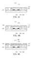
- FIG. 8 is a schematic diagram showing a package apparatus according to a third embodiment of the present invention.
- the package apparatus 6 that is formed basically the same as the package apparatus 4 shown in the second embodiment, comprises: a first wiring layer 200 , a metal layer 210 , a first dielectric material layer 400 , a second dielectric material layer 410 , a conductor layer 420 , a conductive pillar layer 220 , a passive component 230 , a first molding compound layer 240 , a second wiring layer 250 , and a protection layer 260 .
- the first wiring layer 200 has a first surface 202 and a second surface 204 that are arranged opposite to each other.
- the metal layer 210 is disposed on the first surface 202 of the first wiring layer 200 .
- the first dielectric material layer 400 is disposed on a specific portion of the first wiring layer 200 in a manner that the first dielectric material layer 400 is not to be exposed on the first surface 202 of the first wiring layer 200 while being positioned not lower than the second surface 204 of the first wiring layer 200 .
- the second dielectric material layer is disposed on the first dielectric material layer 400 .
- the conductor layer 420 is disposed on the first wiring layer 200 .
- the conductive pillar layer 220 is disposed on conductor layer 420 , forming a concave structure 222 with the conductor layer 420 .
- the passive component 230 is disposed on and electrically connected to the second surface 204 of the first wiring layer 200 in the concave structure 222 .
- the first molding compound layer 240 is disposed on a portion 224 of the second dielectric material layer 410 , the conductor layer 420 and the conductive pillar layer 220 while allowing the same to cover the passive component 230 in a manner that the first molding compound layer 240 is not exposed on one end 226 of the conductive pillar layer 220 . It is noted that although the first molding compound layer 240 is formed covering on every portion of the second dielectric material layer 410 , the conductor layer 420 and the conductive pillar layer 220 , but it is not limited thereby.
- the first molding compound layer 240 can be composed of a material selected from the group consisting of novolac-based resin, epoxy-based resin, silicon-based resign and other molding compounds, but it is also not limited thereby.
- the second wiring layer 250 is disposed on the first molding compound layer 240 and the end 226 of the conductive pillar layer 220 .
- the protection layer 260 is disposed on the first molding compound layer 240 and the second wiring layer 250 .
- the package apparatus 6 can further comprises: an external component 270 , a second molding compound layer 280 and a plurality of metal balls 290 , in which the external component 270 is disposed on and electrically connected to the first surface 202 of the first wiring layer 200 ; the second molding compound layer 280 is disposed on the external component 270 and the first surface 202 of the first wiring layer 200 ; and the plural metal balls 290 are disposed on the second wiring layer 250 .
- the external component is a unit selected from the group consisting of: an active component, a passive component, a semiconductor chip and a flexible circuit board, but is not limited thereby.
- FIG. 9 is a flow chart depicting steps performing in a method for manufacturing a package apparatus of the second embodiment
- FIG. 10A to FIG. 10R are schematic diagrams illustrating the manufacturing of a package apparatus of the first embodiment.
- a method 7 for manufacturing the package apparatus 6 of FIG. 5 comprises the following steps:
- step S 702 providing a metal carrier 300 composed of a first side 302 and a second side 304 that are arranged opposite to each other, as shown in FIG. 10A ;
- step S 704 forming a first dielectric material layer 400 and a sixth photoresist layer 360 respectively on the second side 304 of the metal carrier 300 and the first side 302 of the metal carrier 304 , as shown in FIG. 10B , whereas the first dielectric material layer 400 is formed by first a coating process and then a photolithography and etching process, and the fourth photoresist layer 340 is formed by a dry-film lamination process in this embodiment, but is not limited thereby;
- step S 706 forming a first wiring layer 200 on the second side 304 of the metal carrier 300 while allowing the first dielectric material layer 400 to be disposed within a specific portion of the first wiring layer 200 in a manner that the first dielectric material layer 400 is not lower than the first wiring layer 200 , as shown in FIG. 10C , whereas the first wiring layer 200 is formed using an electrolytic plating process in this embodiment, but is not limited thereby, and moreover, the first wiring layer 200 can be a wiring layer with patterns which includes at least one wire and a chip seat, and the first wiring layer 200 can be made of a metal, such as copper;
- step S 708 forming a second dielectric material layer 410 on the first dielectric material layer 400 , as shown in FIG. 10D , whereas the second wiring layer 610 is formed using first a coating process and then a photolithography and etching process, but is not limited thereby;
- step S 710 enabling a seventh photoresist layer 370 to be formed on the first dielectric material layer 400 and the first wiring layer 200 while enabling the second dielectric material layer 410 to be positioned not lower than the seventh photoresist layer 370 , as shown in FIG. 10E , whereas the seventh photoresist layer 350 is formed by a photography process in this embodiment, but is not limited thereby;
- step S 712 forming a conductor layer 420 on the first wiring layer 200 while enabling the second dielectric material layer 410 to be positioned not lower tan than the conductor layer 420 , as shown in FIG. 10F , whereas the conductor layer 420 is formed by an electrolytic plating process in this embodiment, but is not limited thereby, and the conductor layer can be made from a metal, such as copper;
- step S 714 forming an eighth photoresist layer 380 on the second dielectric material layer 410 , the seventh photoresist layer 370 and the conductor layer 420 , as shown in FIG. 10G , whereas the eighth photoresist layer 380 is formed by a dry-film lamination process in this embodiment, but is not limited thereby;
- step S 716 removing a portion of the eighth photoresist layer 380 for exposing the conductor layer 420 , as shown in FIG. 10H , whereas the removal of the eighth photoresist layer 380 is performed using a photography process, but is not limited thereby;
- step S 718 forming a conductive pillar layer 220 on the conductor layer 420 , as shown in FIG. 10I , whereas the conductive pillar layer 220 is formed using an electrolytic plating process in this embodiment, but is not limited thereby, and moreover, the conductive pillar layer 220 includes at least one conductive pillar that can be made of a metal, such as copper and is formed at a position corresponding to the wires and the chip seat of the conductor layer 420 ;
- step S 720 removing the sixth photoresist layer 360 , the seventh photoresist layer 370 and the eighth photoresist layer 380 so as to respectively exposing the first dielectric material layer 400 on the second side 304 of the metal carrier 300 , and exposing the first wiring layer 200 on the second side 304 of the metal carrier 300 , and then enabling the second dielectric material layer 410 to be disposed on the first dielectric material layer 400 , and forming a conductive pillar layer 200 on the first wiring layer 200 while allowing the conductive pillar layer 220 to form a concave structure 222 with the conductor layer 420 , as shown in FIG. 10J , whereas the first dielectric material layer 400 is disposed within a specific portion of the first wiring layer 200 in a manner that the first dielectric material layer 400 is positioned not lower than the first wiring layer 200 ;
- step S 722 providing a passive component 230 to be disposed on and electrically connected to the first wiring layer 200 in the concave structure 222 , as shown in FIG. 10K ;
- step S 724 forming a first molding compound layer 240 while allowing the same to cover the first dielectric material layer 400 , the second dielectric material layer 410 , the first wiring layer 200 , the conductor layer 420 , the passive component 230 , the conductive pillar layer 220 and the second side 304 of the metal carrier 300 , as shown in FIG.
- the first molding compound layer 240 is formed by a transfer molding process, and can be made from a material selected from the group consisting of novolac-based resin, epoxy-based resin, silicon-based resign and other molding compounds, whichever can be heated to a liquid state so as to be poured on the second side 304 of the metal carrier 300 for allowing the same to cover the first dielectric material layer 400 , the second dielectric material layer 410 , the first wiring layer 200 , the conductor layer 420 , the passive component 230 and the conductive pillar layer 220 under a high-temperature and high-pressure condition, and thereafter, to be cured into the first molding compound layer 240 , and moreover the first molding compound layer 240 can be composed of a kind of filler, such as a powder silicon dioxide; and in another embodiment, the first molding compound layer 240 can be formed by the use of an injection molding process or a compression molding process, and the formation of the first molding compound layer 240 can include the steps of: providing a material selected from the group consisting of no
- step S 726 enabling one end 226 of the conductive pillar layer 220 to be exposed, as shown in FIG. 10M , whereas in this embodiment, the exposing of the end 226 of the conductive pillar layer 220 is enabled by grinding and removing a portion of the first molding compound layer 240 , however, under ideal condition, the end 226 of the conductive pillar layer 220 is positioned coplanar with the first molding compound layer 240 , by that the exposing of the end 226 of the conductive pillar layer 220 can be achieved simultaneously with the formation of the first molding compound layer 240 , and thus the process for grinding and removing of the first molding compound layer 240 can be avoided;
- step S 728 forming a second wiring layer 250 on the first molding compound layer 240 and the exposed end 226 of the conductive pillar layer 220 , as shown in FIG. 10N
- the second wiring layer 250 can be formed by the use of an electroless plating process, a sputtering coating process, or a thermal coating process, but is not limited thereby
- the second wiring layer 250 can be a wiring layer with patterns which includes at least one wire and is a layer formed at a position corresponding to the end 226 of the conductive pillar layer 220 , moreover, the second wiring layer 250 can be made of a metal, such as copper;
- step S 730 forming a protection layer 260 on the first molding compound layer 240 and the second wiring layer 250 while allowing a portion of the second wiring layer 250 to expose, as shown in FIG. 10O , whereas the protection layer 260 is used for insulating wires in the second wiring layer 250 ;
- step S 732 removing a portion of the metal carrier 300 so as to form a window 306 while allowing the first wiring layer 200 and the first dielectric material layer 400 to be exposed therefrom, as shown in FIG. 10P , whereas the removal of the metal carrier 300 can be performed using a photolithography and etching process, and moreover, the wires and the chip seat of the first wiring layer 200 is also exposed from the window 306 , and thus the portion of the metal carrier 300 that is not removed is substantially being formed into a metal layer 210 ;
- step S 734 providing an external component 270 to be disposed on and electrically connected to the first surface 202 of the first wiring layer 200 , as shown in FIG. 10Q , whereas, in an embodiment, the external component 270 can be an active component, a passive component, a semiconductor chip or a flexible circuit board, but is not limited thereby;
- step S 736 forming a second molding compound layer 280 while allowing the same to cover the external component 270 and the first surface 202 of the first wiring layer 200 , as shown in FIG. 10R
- the second molding compound layer 280 is formed by a transfer molding process, and can be made from a material selected from the group consisting of novolac-based resin, epoxy-based resin, silicon-based resign and other molding compounds, whichever can be heated to a liquid state so as to be poured on the second side 304 of the metal carrier 300 for allowing the same to cover the external component 270 and the first surface 202 of the first wiring layer 200 , under a high-temperature and high-pressure condition, and thereafter, to be cured into the second molding compound layer 280
- the second molding compound layer 280 can be composed of a kind of filler, such as a powder silicon dioxide; and in another embodiment, the second molding compound layer 280 can be formed by the use of an injection molding process or a compression molding process;
- step S 738 forming a plurality of metal balls 290 on the second wiring layer 250 , as shown in FIG. 10S , whereas each of the metal balls 290 can be made of a metal, such as copper;
- step S 740 enabling a cutting process C to be performed upon at least one layer selected from the group consisting of: the first wiring layer 200 , the metal layer 210 , the conductive pillar layer 220 , the first molding compound layer 240 , the second wiring layer 250 , and the protection layer 260 , as shown in FIG. 4Q , by that a package apparatus 6 of FIG. 8 can be achieved.
- the package apparatus 6 of the third embodiment is additionally formed with one conductor layer, by that the height of the conductive pillar layer is lowered and then the manufacture difficulty is reduced. Moreover, since the thickness of the corresponding first molding compound layer is also reduced that the work for grinding and removal the first molding compound layer to a thinner layer is minimized, the complexity of the manufacture process is reduced and thus the manufacture cost is lowered.
- the present invention provides a package apparatus, using which a molding compound layer can be used as the major material in the manufacturing of a coreless substrate, and therefore not only a less expensive molding compound substrate can be used for replacing the costly conventional fiberglass substrate, but also the conventional expensive and time consuming laser blind/buried hole formation process on four-layered structure can be replaced by a faster and simpler electroplating conductive pillar process on less costly two-layered structure.
- the package apparatus 4 uses the first dielectric material layer to replace the use of the first photoresist layer in the first embodiment, by that two dry-film lamination processes and one film removal process can be saved and avoided in the method for forming the package apparatus 4 of the second embodiment, and thus the risk of incomplete film removal can be avoided.
- gaps between wires in the first wiring layer can be filled by the first dielectric material layer at the same time when the first molding compound layer is being formed, the risk of having air bubbles in wire gaps due to insufficient filling of the first molding compound layer can also be avoided.
- the package apparatus 6 is additionally formed with one conductor layer, by that the height of the conductive pillar layer is lowered and then the manufacture difficulty is reduced. Moreover, since the thickness of the corresponding first molding compound layer is also reduced that the work for grinding and removal the first molding compound layer to a thinner layer is minimized, the complexity of the manufacture process is reduced and thus the manufacture cost is lowered.
- FIG. 11 is a schematic diagram showing a package apparatus according to a fourth embodiment of the present invention.
- the package apparatus 8 comprises: a first wiring layer 500 , a metal layer 510 , a first dielectric material layer 520 , a second wiring layer 530 , a conductive pillar layer 540 , a passive component 550 , a first molding compound layer 560 , a third wiring layer 570 , and a protection layer 580 .
- the first wiring layer 500 has a first surface 502 and a second surface 504 that are arranged opposite to each other.
- the first dielectric material layer 520 is disposed on a specific portion of the first wiring layer 500 in a manner that the first dielectric material layer 520 is not to be exposed on the first surface 502 of the first wiring layer 500 .
- the second wiring layer 530 is disposed on the first wiring layer 500 and the first dielectric material layer 520 .
- the metal layer 510 is disposed on the first surface 502 of the first wiring layer 500 .
- the conductive pillar layer 540 is disposed on the second wiring layer 530 , forming a concave structure 542 with the second wiring layer 530 .
- the passive component 550 is disposed on and electrically connected to the second wiring layer 530 in the concave structure 542 .
- the first molding compound layer 560 is disposed on a specific portion 544 of the second wiring layer 530 and the conductive pillar layer 540 while allowing the same to cover the passive component 550 in a manner that the first molding compound layer 560 is not exposed on one end 546 of the conductive pillar layer 540 . It is noted that although the first molding compound layer 560 is formed covering on every portion of the second wiring layer 530 and the conductive pillar layer 540 , but it is not limited thereby. Moreover, the first molding compound layer 560 can be composed of a material selected from the group consisting of novolac-based resin, epoxy-based resin, silicon-based resign and other molding compounds, but it is also not limited thereby.
- the third wiring layer 570 is disposed on the first molding compound layer 560 and the end 546 of the conductive pillar layer 540 .
- the protection layer 580 is disposed on the first molding compound layer 560 and the third wiring layer 570 .
- the package apparatus 8 can further comprises: an external component 590 , a second molding compound layer 592 and a plurality of metal balls 594 , in which the external component 590 is disposed on and electrically connected to the first surface 502 of the first wiring layer 500 ; the second molding compound layer 592 is disposed on the external component 590 and the first surface 502 of the first wiring layer 500 ; and the plural metal balls 594 are disposed on the third wiring layer 570 .
- the external component 590 is a unit selected from the group consisting of: an active component, a passive component, a semiconductor chip and a flexible circuit board, but is not limited thereby.
- FIG. 12 is a flow chart depicting steps performing in a method for manufacturing a package apparatus of the fourth embodiment
- FIG. 13A to FIG. 13R are schematic diagrams illustrating the manufacturing of a package apparatus of the fourth embodiment.
- a method 9 for manufacturing the package apparatus 8 of FIG. 11 comprises the following steps:
- step S 902 providing a metal carrier 600 composed of a first side 602 and a second side 604 that are arranged opposite to each other, as shown in FIG. 13A ;
- step S 904 forming a first wiring layer 500 on the second side 604 of the metal carrier 600 , as shown in FIG. 13B , whereas the first wiring layer 500 is formed first using an electroless plating process, a sputtering coating process, or a thermal coating process, and then a photography and etching process in this embodiment, but is not limited thereby, and moreover, the first wiring layer 500 can be a wiring layer with patterns which includes at least one wire and at least one chip seat, and the first wiring layer 500 can be made of a metal, such as copper;
- step S 906 forming a first dielectric material layer 520 on the second side 604 of the metal carrier 600 and the first wiring layer 500 and also forming a first photoresist layer 610 on the first side 602 of the metal carrier 600 , as shown in FIG. 13C , whereas the first dielectric material layer 520 is formed by first a coating process and then a photolithography and etching process, and the first photoresist layer 610 is formed by a dry-film lamination process in this embodiment, but is not limited thereby;
- step S 908 forming a second wiring layer 530 on the first wiring layer 500 and the first dielectric material layer 520 , as shown in FIG. 13D , whereas the second wiring layer 530 is formed first using an electroless plating process, a sputtering coating process, or a thermal coating process, and then a photography and etching process in this embodiment, but is not limited thereby, and moreover, the second wiring layer 530 can be a wiring layer with patterns which includes at least one wire, disposed at a position corresponding to the first wiring layer 500 that is exposed;
- step S 910 enabling a second photoresist layer 620 to be formed on the first dielectric material layer 520 and the second wiring layer 530 , as shown in FIG. 13E , whereas the second photoresist layer 620 is formed by a dry-film lamination process in this embodiment, but is not limited thereby;
- step S 912 removing a portion of the second photoresist layer 620 for exposing the second wiring layer 530 , as shown in FIG. 13F , whereas the removal of the second photoresist layer 620 is achieved using a photography process in this embodiment, but it is not limited thereby;
- step S 914 forming a conductive pillar layer 540 on the second wiring layer 530 , as shown in FIG. 13G , whereas the conductive pillar layer 540 is formed using an electrolytic plating process in this embodiment, but is not limited thereby, and moreover, the conductive pillar layer 540 includes at least one conductive pillar that can be made of a metal, such as copper and is formed at a position corresponding to the wires of the second wiring layer 530 ;
- step S 916 removing the first photoresist layer 610 and the second photoresist layer 620 so as to respectively exposing the first wiring layer 500 on the second side 604 of the metal carrier 600 , and exposing the first the first dielectric material layer 520 on the first wiring layer 500 and the second side 604 of the metal carrier 600 , and then forming a second wiring layer 530 on the first wiring layer 500 and the first dielectric material layer 520 and forming a conductive pillar layer 540 on the second wiring layer 530 while enabling the conductive pillar layer 540 conductive pillar layer 540 to form a concave structure 542 with the second wiring layer 530 , as shown in FIG. 13H ;
- step S 918 providing a passive component 550 to be disposed on and electrically connected to second wiring layer 530 in the concave structure 542 , as shown in FIG. 13I ;
- step S 920 forming a first molding compound layer 560 while allowing the same to cover the first dielectric material layer 520 , the second wiring layer 530 second wiring layer 530 , the conductive pillar layer 540 , the passive component 550 , and the second side 604 of the metal carrier 600 , as shown in FIG.
- the first molding compound layer 560 is formed by a transfer molding process, and can be made from a material selected from the group consisting of novolac-based resin, epoxy-based resin, silicon-based resign and other molding compounds, whichever can be heated to a liquid state so as to be poured on the second side 604 of the metal carrier 600 for allowing the same to cover the first dielectric material layer 520 , the second wiring layer 530 , he conductive pillar layer 540 , and the passive component 550 under a high-temperature and high-pressure condition, and thereafter, to be cured into the first molding compound layer 560 , and moreover the first molding compound layer 560 can be composed of a kind of filler, such as a powder silicon dioxide; and in another embodiment, the first molding compound layer 560 can be formed by the use of an injection molding process or a compression molding process, and the formation of the first molding compound layer 560 can include the steps of: providing a molding compound to be heated to a liquid state,
- step S 922 enabling one end 546 of the conductive pillar layer 540 to be exposed, as shown in FIG. 13K , whereas in this embodiment, the exposing of the end 546 of the conductive pillar layer 540 is enabled by grinding and removing a portion of the first molding compound layer 560 , however, under ideal condition, the end 546 of the conductive pillar layer 540 is positioned coplanar with the first molding compound layer 560 , by that the exposing of the end 546 of the conductive pillar layer 540 can be achieved simultaneously with the formation of the first molding compound layer 560 , and thus the process for grinding and removing of the first molding compound layer 560 can be avoided;
- step S 924 forming a third wiring layer 570 on the first molding compound layer 560 and the exposed end 546 of the conductive pillar layer 540 , as shown in FIG. 13L
- the third wiring layer 570 can be formed by the use of an electroless plating process, a sputtering coating process, or a thermal coating process, but is not limited thereby
- the third wiring layer 570 can be a wiring layer with patterns which includes at least one wire that is to be formed at a position corresponding to the end 546 of the conductive pillar layer 540 , moreover, the third wiring layer 570 can be made of a metal, such as copper;
- step S 926 forming a protection layer 580 on the first molding compound layer 560 and the third wiring layer 570 while allowing a portion of the third wiring layer 570 to expose, as shown in FIG. 13M , whereas the protection layer 580 is used for insulating wires in the third wiring layer 570 ;
- step S 928 removing a portion of the metal carrier 600 so as to form a window 606 while allowing the first wiring layer 500 and the first dielectric material layer 520 to be exposed therefrom, as shown in FIG. 13N , whereas the removal of the metal carrier 600 can be performed using a photolithography and etching process, and moreover, the wires and the chip seat of the first wiring layer 500 is also exposed from the window 606 , and thus the portion of the metal carrier 600 that is not removed is substantially being formed into a metal layer 510 ;
- step S 930 providing an external component 590 to be disposed on and electrically connected to the first surface 502 of the first wiring layer 500 , as shown in FIG. 13O , whereas, in an embodiment, the external component 590 can be an active component, a passive component, a semiconductor chip or a flexible circuit board, but is not limited thereby;
- step S 932 forming a second molding compound layer 592 while allowing the same to cover the external component 590 and the first surface 502 of the first wiring layer 500 , as shown in FIG. 13P
- the second molding compound layer 592 is formed by a transfer molding process, and can be made from a material selected from the group consisting of novolac-based resin, epoxy-based resin, silicon-based resign and other molding compounds, whichever can be heated to a liquid state so as to be poured on the second side 604 of the metal carrier 600 for allowing the same to cover the external component 590 and the first surface 502 of the first wiring layer 500 , under a high-temperature and high-pressure condition, and thereafter, to be cured into the second molding compound layer 592
- the second molding compound layer 592 can be composed of a kind of filler, such as a powder silicon dioxide; and in another embodiment, the second molding compound layer 592 can be formed by the use of an injection molding process or a compression molding process;
- step S 934 forming a plurality of metal balls 594 on the third wiring layer 570 , as shown in FIG. 13Q , whereas each of the metal balls 594 can be made of a metal, such as copper;
- step S 936 enabling a cutting process C to be performed upon at least one layer selected from the group consisting of: the first wiring layer 500 , the metal layer 510 , the first dielectric material layer 520 , the second wiring layer 530 , the first molding compound layer 560 , the third wiring layer 570 , and the protection layer 580 , as shown in FIG. 13R , by that a package apparatus 8 of FIG. 11 can be achieved.
- the package apparatus 8 in this fourth embodiment uses the first molding compound layer as a coreless substrate so that the conventional expensive fiberglass substrate is not required, and also the conventional expensive and time consuming laser blind/buried hole formation process on four-layered structure can be replaced by a faster and simpler electroplating conductive pillar process on less costly three-layered structure.
- FIG. 14 is a schematic diagram showing a package apparatus according to a fifth embodiment of the present invention.
- the package apparatus 10 that is formed basically the same as the package apparatus 8 shown in the fourth embodiment, comprises: a first wiring layer 500 , a metal layer 510 , a first dielectric material layer 520 , a second dielectric material layer 522 , a second wiring layer 530 , a conductive pillar layer 540 , a passive component 550 , a first molding compound layer 560 , a third wiring layer 570 , and a protection layer 580 .
- the first wiring layer 500 has a first surface 502 and a second surface 504 that are arranged opposite to each other.
- the metal layer is disposed on the first surface 502 of the first wiring layer 500 .
- the first dielectric material layer 520 is disposed on a specific portion of the first wiring layer 500 in a manner that the first dielectric material layer 520 is not to be exposed on the first surface 502 of the first wiring layer 500 while being positioned not lower than the second surface 504 of the first wiring layer 500 .
- the second dielectric material layer 522 is disposed on the first wiring layer 500 and the first dielectric material layer 520 .
- the second wiring layer 530 is disposed on the first wiring layer 500 and the second dielectric material layer 522 .
- the metal layer 510 is disposed on the first surface 502 of the first wiring layer 500 .
- the conductive pillar layer 540 is disposed on the second wiring layer 530 , forming a concave structure 542 with the second wiring layer 530 .
- the passive component 550 is disposed on and electrically connected to the first wiring layer 500 in the concave structure 542 .
- the first molding compound layer 560 is disposed on a specific portion 544 of the first dielectric material layer 520 , the second dielectric material layer 522 , the second wiring layer 530 and the conductive pillar layer 540 while allowing the same to cover the passive component 550 in a manner that the first molding compound layer 560 is not exposed on one end 546 of the conductive pillar layer 540 .
- first molding compound layer 560 is formed covering on every portion of the second wiring layer 530 and the conductive pillar layer 540 , but it is not limited thereby. Moreover, the first molding compound layer 560 can be composed of a material selected from the group consisting of novolac-based resin, epoxy-based resin, silicon-based resign and other molding compounds, but it is also not limited thereby.
- the third wiring layer 570 is disposed on the first molding compound layer 560 and the end 546 of the conductive pillar layer 540 .
- the protection layer 580 is disposed on the first molding compound layer 560 and the third wiring layer 570 .
- the package apparatus 10 can further comprises: an external component 590 , a second molding compound layer 592 and a plurality of metal balls 594 , in which the external component 590 is disposed on and electrically connected to the first surface 502 of the first wiring layer 500 ; the second molding compound layer 592 is disposed on the external component 590 and the first surface 502 of the first wiring layer 500 ; and the plural metal balls 594 are disposed on the third wiring layer 570 .
- the external component 590 is a unit selected from the group consisting of: an active component, a passive component, a semiconductor chip and a flexible circuit board, but is not limited thereby.
- FIG. 15 is a flow chart depicting steps performing in a method for manufacturing a package apparatus of the fifth embodiment
- FIG. 16A to FIG. 16T are schematic diagrams illustrating the manufacturing of a package apparatus of the fifth embodiment.
- a method 11 for manufacturing the package apparatus 10 of FIG. 14 comprises the following steps:
- step S 1102 providing a metal carrier 600 composed of a first side 602 and a second side 604 that are arranged opposite to each other, as shown in FIG. 16A ;
- step S 1104 forming a first dielectric material layer 520 and a third photoresist layer 630 respectively on the second side 604 of the metal carrier 600 and the first side 602 of the metal carrier 600 , as shown in FIG. 16B , whereas the first dielectric material layer 520 is formed by first a coating process, and the third photoresist layer 630 is formed by a dry-film lamination process in this embodiment, but is not limited thereby;
- step S 1106 forming a first wiring layer 500 on the second side 604 of the metal carrier 600 while allowing the first dielectric material layer 520 to be disposed within a specific portion of the first wiring layer 500 in a manner that the first dielectric material layer 520 is not lower than the first wiring layer 500 , as shown in FIG. 16C , whereas the first wiring layer 500 is formed using an electrolytic plating process in this embodiment, but is not limited thereby, and moreover, the first wiring layer 500 can be a wiring layer with patterns which includes at least one wire and a chip seat, and the first wiring layer 500 can be made of a metal, such as copper;
- step S 1108 forming a second dielectric material layer 522 on the first wiring layer 500 and the first dielectric material layer 520 , as shown in FIG. 16D , whereas the second dielectric material layer 522 is formed using a coating process in this embodiment, but is not limited thereby;
- step S 1110 enabling a fourth photoresist layer 640 to be formed on the first wiring layer 500 , the first dielectric material layer 520 and the second dielectric material layer 522 , as shown in FIG. 16E , whereas the fourth photoresist layer 640 is formed first by a dry-film lamination process and then a photolithography process in this embodiment, but is not limited thereby;
- step S 1112 forming a second wiring layer 530 on the first wiring layer 500 and the first dielectric material layer 520 , as shown in FIG. 16F , whereas the second wiring layer 530 is formed first using an electroless plating process, but is not limited thereby, and moreover, the second wiring layer 530 , that can be made of a metal, such as copper, includes at least one wire, disposed at a position corresponding to the wires of the first wiring layer 500 ;
- step S 1114 forming a fifth photoresist layer 650 on the fourth photoresist layer 640 and the second wiring layer 530 , as shown in FIG. 16G , whereas the fifth photoresist layer 650 can be formed using a dry-film lamination process in this embodiment, but is not limited thereby;
- step S 1116 removing a portion of the fifth photoresist layer 650 for exposing the second wiring layer 300 , as shown in FIG. 16H , whereas the removal of a portion of the fifth photoresist layer 650 is performed using a photolithography process, but is not limited thereby;
- step S 1118 forming a conductive pillar layer 540 on the second wiring layer 530 , as shown in FIG. 16I , whereas the conductive pillar layer 540 is formed using an electrolytic plating process in this embodiment, but is not limited thereby, and moreover, the conductive pillar layer 540 includes at least one conductive pillar that can be made of a metal, such as copper and is formed at a position corresponding to the wires of the second wiring layer 530 ;
- step S 1120 removing the fourth photoresist layer 640 and the fifth photoresist layer 650 so as to respectively exposing the first dielectric material layer 520 on the second side 604 of the metal carrier 600 , and exposing the first wiring layer 500 on the second side 604 of the metal carrier 600 , and then forming a conductive pillar layer 540 on the first wiring layer 500 while allowing the conductive pillar layer 540 to form a concave structure 542 with the first wiring layer 500 , as shown in FIG. 16J , whereas the first dielectric material layer 520 is disposed within a specific portion of the first wiring layer 500 in a manner that the first dielectric material layer 520 is positioned not lower than the first wiring layer 500 ;
- step S 1122 providing a passive component 550 to be disposed on and electrically connected to the first wiring layer 500 in the concave structure 542 , as shown in FIG. 16K ;
- step S 1124 forming a first molding compound layer 560 while allowing the same to cover the first dielectric material layer 520 , the first wiring layer 500 , the second dielectric material layer 522 , the second wiring layer 530 , the conductive pillar layer 540 , the passive component 550 , and the second side 604 of the metal carrier 600 , as shown in FIG.
- the first molding compound layer 560 is formed by a transfer molding process, and can be made from a material selected from the group consisting of novolac-based resin, epoxy-based resin, silicon-based resign and other molding compounds, whichever can be heated to a liquid state so as to be poured on the second side 604 of the metal carrier 600 for allowing the same to cover the first dielectric material layer 520 , the first wiring layer 500 , the second dielectric material layer 522 , the second wiring layer 530 , the conductive pillar layer 540 , and the passive component 550 under a high-temperature and high-pressure condition, and thereafter, to be cured into the first molding compound layer 560 , and moreover the first molding compound layer 560 can be composed of a kind of filler, such as a powder silicon dioxide; and in another embodiment, the first molding compound layer 560 can be formed by the use of an injection molding process or a compression molding process, and the formation of the first molding compound layer 560 can include the steps of
- step S 1126 enabling one end 546 of the conductive pillar layer 540 to be exposed, as shown in FIG. 16M , whereas in this embodiment, the exposing of the end 546 of the conductive pillar layer 540 is enabled by grinding and removing a portion of the first molding compound layer 560 , however, under ideal condition, the end 546 of the conductive pillar layer 540 is positioned coplanar with the first molding compound layer 560 , by that the exposing of the end 546 of the conductive pillar layer 540 can be achieved simultaneously with the formation of the first molding compound layer 560 , and thus the process for grinding and removing of the first molding compound layer 560 can be avoided;
- step S 1128 forming a third wiring layer 570 on the first molding compound layer 560 and the exposed end 546 of the conductive pillar layer 540 , as shown in FIG. 16N
- the third wiring layer 570 can be formed by the use of an electroless plating process, a sputtering coating process, or a thermal coating process, but is not limited thereby
- the third wiring layer 570 can be a wiring layer with patterns which includes at least one wire that is to be formed at a position corresponding to the end 546 of the conductive pillar layer 540 , moreover, the third wiring layer 570 can be made of a metal, such as copper;
- step S 1130 forming a protection layer 580 on the first molding compound layer 560 and the third wiring layer 570 while allowing a portion of the third wiring layer 570 to expose, as shown in FIG. 16O , whereas the protection layer 580 is used for insulating wires in the third wiring layer 570 ;
- step S 1132 removing a portion of the metal carrier 600 so as to form a window 606 while allowing the first wiring layer 500 and the first dielectric material layer 520 to be exposed therefrom, as shown in FIG. 16P , whereas the removal of the metal carrier 600 can be performed using a photolithography and etching process, and moreover, the wires and the chip seat of the first wiring layer 500 is also exposed from the window 606 , and thus the portion of the metal carrier 600 that is not removed is substantially being formed into a metal layer 510 ;
- step S 1134 providing an external component 590 to be disposed on and electrically connected to the first surface 502 of the first wiring layer 500 , as shown in FIG. 16Q , whereas, in an embodiment, the external component 590 can be an active component, a passive component, a semiconductor chip or a flexible circuit board, but is not limited thereby;
- step S 1136 forming a second molding compound layer 592 while allowing the same to cover the external component 590 and the first surface 502 of the first wiring layer 500 , as shown in FIG. 16R
- the second molding compound layer 592 is formed by a transfer molding process, and can be made from a material selected from the group consisting of novolac-based resin, epoxy-based resin, silicon-based resign and other molding compounds, whichever can be heated to a liquid state so as to be poured on the second side 604 of the metal carrier 600 for allowing the same to cover the external component 590 and the first surface 502 of the first wiring layer 500 , under a high-temperature and high-pressure condition, and thereafter, to be cured into the second molding compound layer 592
- the second molding compound layer 592 can be composed of a kind of filler, such as a powder silicon dioxide; and in another embodiment, the second molding compound layer 592 can be formed by the use of an injection molding process or a compression molding process;
- step S 1138 forming a plurality of metal balls 594 on the third wiring layer 570 , as shown in FIG. 16S , whereas each of the metal balls 594 can be made of a metal, such as copper;
- step S 1140 enabling a cutting process C to be performed upon at least one layer selected from the group consisting of: the first wiring layer 500 , the metal layer 510 , the first dielectric material layer 520 , the second dielectric material layer 522 , the second wiring layer 530 , the first molding compound layer 560 , the third wiring layer 570 , and the protection layer 580 , as shown in FIG. 16T , by that a package apparatus 10 of FIG. 14 can be achieved.
- the package apparatus 10 of the fifth embodiment is designed for disposing its passive component on the first wiring layer that is being positioned lower than the second wiring layer, by that the height of the conductive pillar layer is lowered and then the manufacture difficulty is reduced. Moreover, since the thickness of the corresponding first molding compound layer is also reduced that the work for grinding and removal the first molding compound layer to a thinner layer is minimized, the complexity of the manufacture process is reduced and thus the manufacture cost is lowered.
- the present invention provides a package apparatus, using which a molding compound layer can be used as the major material in the manufacturing of a coreless substrate, and therefore not only a less expensive molding compound substrate can be used for replacing the costly conventional fiberglass substrate, but also the conventional expensive and time consuming laser blind/buried hole formation process on four-layered structure can be replaced by a faster and simpler electroplating conductive pillar process on less costly three-layered structure.
- the package apparatus 10 is designed for disposing its passive component on the first wiring layer that is being positioned lower than the second wiring layer, by that the height of the conductive pillar layer is lowered and then the manufacture difficulty is reduced. Moreover, since the thickness of the corresponding first molding compound layer is also reduced that the work for grinding and removal the first molding compound layer to a thinner layer is minimized, the complexity of the manufacture process is reduced and thus the manufacture cost is lowered.
- FIG. 17 is a schematic diagram showing a package apparatus according to a sixth embodiment of the present invention.
- the package apparatus 12 comprises: a first wiring layer 700 , a metal layer 710 , a dielectric material layer 720 , a conductive pillar layer 730 , an adhesive layer 740 , a passive component 750 , a first molding compound layer 760 , a second wiring layer 770 , and a protection layer 780 .
- the first wiring layer 700 has a first surface 702 and a second surface 704 that are arranged opposite to each other.
- the metal layer 710 is disposed on the first surface 702 of the first wiring layer 700 .
- the dielectric material layer 720 is disposed on a specific portion of the first wiring layer 700 in a manner that the dielectric material layer 720 is not to be exposed on the first surface 702 of the first wiring layer 700 while being positioned not lower than the second surface 704 of the first wiring layer 700 .
- the conductive pillar layer 730 is disposed on the second surface 704 of the first wiring layer 700 , forming a concave structure 732 with the first wiring layer 700 .
- the adhesive layer 740 is disposed on the first wiring layer 700 and the dielectric material layer 720 in the concave structure 732 .
- the passive component 750 is disposed on the adhesive layer 740 in the concave structure 732 .
- the first molding compound layer 760 is disposed on a portion 734 of the conductive pillar layer 730 while allowing the same to cover the passive component 750 in a manner that the first molding compound layer 760 is not exposed on one end 736 of the conductive pillar layer 730 . It is noted that although the first molding compound layer 760 is formed covering on every portion of the conductive pillar layer 730 , but it is not limited thereby. Moreover, the first molding compound layer 760 can be composed of a material selected from the group consisting of novolac-based resin, epoxy-based resin, silicon-based resign and other molding compounds, but it is also not limited thereby.
- the second wiring layer 770 is disposed on the first molding compound layer 760 , the end 736 of the conductive pillar layer 730 and the passive component 750 .
- the protection layer 780 is disposed on the first molding compound layer 760 and the second wiring layer 770 .
- the package apparatus 12 can further comprises: an external component 790 , a second molding compound layer 792 and a plurality of metal balls 794 , in which the external component 790 is disposed on and electrically connected to the first surface 702 of the first wiring layer 700 ; the second molding compound layer 792 is disposed on the external component 790 and the first surface 702 of the first wiring layer 700 ; and the plural metal balls 794 are disposed on the second wiring layer 770 .
- the external component 790 is a unit selected from the group consisting of: an active component, a passive component, a semiconductor chip and a flexible circuit board, but is not limited thereby.
- FIG. 18 is a flow chart depicting steps performing in a method for manufacturing a package apparatus according to a sixth embodiment of the present invention
- FIG. 19A to FIG. 19R are schematic diagrams illustrating the manufacturing of a package apparatus of the first embodiment.
- a method 13 for manufacturing the package apparatus 12 of FIG. 17 comprises the following steps:
- step S 1302 providing a metal carrier 800 composed of a first side 802 and a second side 804 that are arranged opposite to each other, as shown in FIG. 19A ;
- step S 1304 forming a dielectric material layer 720 and a first photoresist layer 810 respectively on the second side 804 of the metal carrier 800 and the first side 802 of the metal carrier 304 , as shown in FIG. 19B , whereas the first dielectric material layer 720 is formed by first a coating process and then a photolithography and etching process, and the first photoresist layer 810 is formed by a dry-film lamination process in this embodiment, but is not limited thereby;
- step S 1306 forming a first wiring layer 700 on the second side 804 of the metal carrier 800 while allowing the dielectric material layer 720 to be disposed within a specific portion of the first wiring layer 700 in a manner that the dielectric material layer 720 is not lower than the first wiring layer 700 , as shown in FIG. 19C , whereas the first wiring layer 700 is formed using an electrolytic plating process in this embodiment, but is not limited thereby, and moreover, the first wiring layer 700 can be a wiring layer with patterns which includes at least one wire and a chip seat, and the first wiring layer 700 can be made of a metal, such as copper;
- step S 1308 enabling a second photoresist layer 820 to be formed on the dielectric material layer 720 and the first wiring layer 700 , as shown in FIG. 19D , whereas the second photoresist layer 820 is formed by a dry-film lamination process in this embodiment, but is not limited thereby;
- step S 1310 removing a portion of the second photoresist layer 820 for exposing the first wiring layer 700 , as shown in FIG. 19E , whereas the removal of the second photoresist layer 820 is achieved using a photography process in this embodiment, but it is not limited thereby;
- step S 1312 forming a conductive pillar layer 730 on the first wiring layer 700 , as shown in FIG. 19F , whereas the conductive pillar layer 730 is formed using an electrolytic plating process in this embodiment, but is not limited thereby, and moreover, the conductive pillar layer 730 includes at least one conductive pillar that can be made of a metal, such as copper and is formed at a position corresponding to the wires and the chip seat of the first wiring layer 700 ;
- step S 1314 removing the first photoresist layer 810 and the second photoresist layer 820 so as to respectively exposing the dielectric material layer 720 on the second side 804 of the metal carrier 800 , and exposing the first wiring layer 700 on the second side 804 of the metal carrier 800 , and then forming a conductive pillar layer 730 on the first wiring layer while allowing the conductive pillar layer 730 to form a concave structure 732 with the first wiring layer 700 , as shown in FIG. 19G , whereas the dielectric material layer 720 is disposed within a specific portion of the first wiring layer 700 in a manner that the dielectric material layer 720 is positioned not lower than the first wiring layer 700 ;
- step S 1316 forming an adhesive layer 740 on the first wiring layer 700 and the dielectric material layer 720 in the concave structure 732 , as shown in FIG. 19H , whereas the adhesive layer 740 is used for insulation;
- step S 1318 providing a passive component 750 to be disposed on the adhesive layer 740 in the concave structure 732 , as shown in FIG. 19I ;
- step S 1320 forming a first molding compound layer 760 while allowing the same to cover the dielectric material layer 720 , the first wiring layer 700 , the adhesive layer 740 , the passive component 750 , the conductive pillar layer 730 and the second side 804 of the metal carrier 800 , as shown in FIG.
- the first molding compound layer 760 is formed by a transfer molding process, and can be made from a material selected from the group consisting of novolac-based resin, epoxy-based resin, silicon-based resign and other molding compounds, whichever can be heated to a liquid state so as to be poured on the second side 804 of the metal carrier 800 for allowing the same to cover the dielectric material layer 720 , the first wiring layer 700 , the adhesive layer 740 , the passive component 750 and the conductive pillar layer 730 under a high-temperature and high-pressure condition, and thereafter, to be cured into the first molding compound layer 760 , and moreover the first molding compound layer 760 can be composed of a kind of filler, such as a powder silicon dioxide; and in another embodiment, the first molding compound layer 760 can be formed by the use of an injection molding process or a compression molding process, and the formation of the first molding compound layer 760 can include the steps of: providing a molding compound to be heated to a liquid state
- step S 1322 enabling one end 736 of the conductive pillar layer 730 to be exposed, as shown in FIG. 19K , whereas in this embodiment, the exposing of the end 736 of the conductive pillar layer 730 is enabled by grinding and removing a portion of the first molding compound layer 760 , however, under ideal condition, the end 736 of the conductive pillar layer 730 is positioned coplanar with the first molding compound layer 760 , by that the exposing of the end 736 of the conductive pillar layer 730 can be achieved simultaneously with the formation of the first molding compound layer 760 , and thus the process for grinding and removing of the first molding compound layer 760 can be avoided;
- step S 1324 forming a second wiring layer 770 on the first molding compound layer 760 , the exposed end 736 of the conductive pillar layer 730 and the passive component 750 , as shown in FIG. 19L
- the second wiring layer 770 can be formed by the use of an electroless plating process, a sputtering coating process, or a thermal coating process, but is not limited thereby
- the second wiring layer 770 can be a wiring layer with patterns which includes at least one wire and is a layer formed at a position corresponding to the end 736 of the conductive pillar layer 730 or the passive component 750 , moreover, the second wiring layer 770 can be made of a metal, such as copper;
- step S 1326 forming a protection layer 780 on the first molding compound layer 760 and the second wiring layer 770 while allowing a portion of the second wiring layer 770 to expose, as shown in FIG. 19M , whereas the protection layer 780 is used for insulating wires in the second wiring layer 770 ;
- step S 1328 removing a portion of the metal carrier 800 so as to form a window 806 while allowing the first wiring layer 700 and the dielectric material layer 720 to be exposed therefrom, as shown in FIG. 19N , whereas the removal of the metal carrier 800 can be performed using a photolithography and etching process, and moreover, the wires and the chip seat of the first wiring layer 700 is also exposed from the window 806 , and thus the portion of the metal carrier 800 that is not removed is substantially being formed into a metal layer 710 ;
- step S 1330 providing an external component 790 to be disposed on and electrically connected to the first surface 702 of the first wiring layer 700 , as shown in FIG. 19O , whereas, in a sixth embodiment, the external component 790 can be an active component, a passive component, a semiconductor chip or a flexible circuit board, but is not limited thereby;
- step S 1332 forming a second molding compound layer 792 while allowing the same to cover the external component 790 and the first surface 702 of the first wiring layer 700 , as shown in FIG. 19P
- the second molding compound layer 792 is formed by a transfer molding process, and can be made from a material selected from the group consisting of novolac-based resin, epoxy-based resin, silicon-based resign and other molding compounds, whichever can be heated to a liquid state so as to be poured on the second side 804 of the metal carrier 800 for allowing the same to cover the external component 790 and the first surface 702 of the first wiring layer 700 , under a high-temperature and high-pressure condition, and thereafter, to be cured into the second molding compound layer 792
- the second molding compound layer 792 can be composed of a kind of filler, such as a powder silicon dioxide; and in another embodiment, the second molding compound layer 792 can be formed by the use of an injection molding process or a compression molding process;
- step S 1334 forming a plurality of metal balls 794 on the second wiring layer 770 , as shown in FIG. 19Q , whereas each of the metal balls 794 can be made of a metal, such as copper;
- step S 1336 enabling a cutting process C to be performed upon at least one layer selected from the group consisting of: the first wiring layer 700 , the metal layer 710 , the conductive pillar layer 730 , the first molding compound layer 760 , the second wiring layer 770 , and the protection layer 780 , as shown in FIG. 19R , by that a package apparatus 12 of FIG. 17 can be achieved.
- the package apparatus 12 in this sixth embodiment uses the first molding compound layer as a coreless substrate so that the conventional expensive fiberglass substrate is not required.
- a laser drilling process is required to be performed repetitively for achieving the conventional laser blind/buried hole formation on four-layered metal structure, which can be an expensive, difficult and time-consuming task in addition to the high cost of the four-layered metal structure. Consequently, by the abovementioned apparatus and method of the present invention, the conventional laser blind/buried hole formation process on four-layered structure can be replaced by a faster and simpler electroplating conductive pillar process on less costly two-layered structure which only require the laser drilling process to be performed only once. Thereby, not only the manufacturing time is reduce as the manufacturing process is simplified, but also the manufacturing cost is lowered.
- the passive component can be insulated from the first wiring layer so that the first wiring layer can be used as a circuit to be engaged directly and electrically to the chips of the external component, leaving the passive component to be electrically conducted via the second wiring layer, and thus saving considerable chips use of space.
Landscapes
- Production Of Multi-Layered Print Wiring Board (AREA)
- Structures Or Materials For Encapsulating Or Coating Semiconductor Devices Or Solid State Devices (AREA)
- Encapsulation Of And Coatings For Semiconductor Or Solid State Devices (AREA)
Abstract
Description
Claims (34)
Applications Claiming Priority (9)
| Application Number | Priority Date | Filing Date | Title |
|---|---|---|---|
| TW103104900A | 2014-02-14 | ||
| TW103104900A TWI534963B (en) | 2014-02-14 | 2014-02-14 | Packaging device and manufacturing method thereof |
| TW103104902A | 2014-02-14 | ||
| TW103104900 | 2014-02-14 | ||
| TW103104896A TWI541960B (en) | 2014-02-14 | 2014-02-14 | Packaging device and manufacturing method thereof |
| TW103104902 | 2014-02-14 | ||
| TW103104902A TWI538119B (en) | 2014-02-14 | 2014-02-14 | Packaging device and manufacturing method thereof |
| TW103104896A | 2014-02-14 | ||
| TW103104896 | 2014-02-14 |
Publications (2)
| Publication Number | Publication Date |
|---|---|
| US20150235916A1 US20150235916A1 (en) | 2015-08-20 |
| US9601402B2 true US9601402B2 (en) | 2017-03-21 |
Family
ID=53798744
Family Applications (1)
| Application Number | Title | Priority Date | Filing Date |
|---|---|---|---|
| US14/505,973 Active 2035-06-12 US9601402B2 (en) | 2014-02-14 | 2014-10-03 | Package apparatus and manufacturing method thereof |
Country Status (1)
| Country | Link |
|---|---|
| US (1) | US9601402B2 (en) |
Families Citing this family (3)
| Publication number | Priority date | Publication date | Assignee | Title |
|---|---|---|---|---|
| US9443797B2 (en) * | 2012-09-14 | 2016-09-13 | STATS ChipPAC Pte. Ltd. | Semiconductor device having wire studs as vertical interconnect in FO-WLP |
| US20170084594A1 (en) * | 2015-09-20 | 2017-03-23 | Qualcomm Incorporated | Embedding die technology |
| CN106601627A (en) * | 2016-12-21 | 2017-04-26 | 江苏长电科技股份有限公司 | Process of first sealing then corrosion electro copper column conduction three-dimensional packaging structure |
Citations (1)
| Publication number | Priority date | Publication date | Assignee | Title |
|---|---|---|---|---|
| US8786062B2 (en) * | 2009-10-14 | 2014-07-22 | Advanced Semiconductor Engineering, Inc. | Semiconductor package and process for fabricating same |
-
2014
- 2014-10-03 US US14/505,973 patent/US9601402B2/en active Active
Patent Citations (1)
| Publication number | Priority date | Publication date | Assignee | Title |
|---|---|---|---|---|
| US8786062B2 (en) * | 2009-10-14 | 2014-07-22 | Advanced Semiconductor Engineering, Inc. | Semiconductor package and process for fabricating same |
Also Published As
| Publication number | Publication date |
|---|---|
| US20150235916A1 (en) | 2015-08-20 |
Similar Documents
| Publication | Publication Date | Title |
|---|---|---|
| JP6263573B2 (en) | Multilayer electronic device and manufacturing method thereof | |
| US20090321932A1 (en) | Coreless substrate package with symmetric external dielectric layers | |
| US8597983B2 (en) | Semiconductor device packaging having substrate with pre-encapsulation through via formation | |
| KR101255954B1 (en) | Printed circuit board and manufacturing method thereof | |
| US20150382469A1 (en) | Package apparatus and manufacturing method thereof | |
| JP6019168B2 (en) | Package structure and manufacturing method thereof | |
| US9214437B1 (en) | Package method | |
| US9583436B2 (en) | Package apparatus and manufacturing method thereof | |
| JP2016111332A (en) | Packaging structure and manufacturing method thereof | |
| TWI513379B (en) | Substrate structure of embedded component and manufacturing method thereof | |
| KR20130014122A (en) | Electronic components embedded pcb and method for manufacturing thereof | |
| US11246223B2 (en) | Package apparatus | |
| CN105321915A (en) | Embedded board and method of manufacturing the same | |
| CN106653730A (en) | Embedded packaging structure based on semiconductor chip packaging body and packaging method thereof | |
| KR20160043357A (en) | Embedded board and method of manufacturing the same | |
| US9601402B2 (en) | Package apparatus and manufacturing method thereof | |
| US20140014398A1 (en) | Coreless subtrate and method of manufacturing the same | |
| KR100923542B1 (en) | Embedded Semiconductor Package Device Using Release Material and Its Manufacturing Method | |
| US8502378B2 (en) | Package unit and stacking structure thereof | |
| JP7131740B2 (en) | Printed circuit boards and packages | |
| TW201640976A (en) | Stacked electronic device and method of manufacturing same | |
| TWI534963B (en) | Packaging device and manufacturing method thereof | |
| TWI538119B (en) | Packaging device and manufacturing method thereof | |
| CN104851847B (en) | Packaging device and manufacturing method thereof | |
| TW201601224A (en) | Package substrate structure and its preparation method |
Legal Events
| Date | Code | Title | Description |
|---|---|---|---|
| AS | Assignment |
Owner name: PHOENIX PIONEER TECHNOLOGY CO., LTD., TAIWAN Free format text: ASSIGNMENT OF ASSIGNORS INTEREST;ASSIGNORS:CHOU, E-TUNG;HU, CHU-CHIN;HSU, SHIH-PING;SIGNING DATES FROM 20140901 TO 20140909;REEL/FRAME:033889/0605 |
|
| FEPP | Fee payment procedure |
Free format text: PAYOR NUMBER ASSIGNED (ORIGINAL EVENT CODE: ASPN); ENTITY STATUS OF PATENT OWNER: SMALL ENTITY |
|
| STCF | Information on status: patent grant |
Free format text: PATENTED CASE |
|
| AS | Assignment |
Owner name: PHOENIX & CORPORATION, CAYMAN ISLANDS Free format text: ASSIGNMENT OF ASSIGNORS INTEREST;ASSIGNOR:PHOENIX PIONEER TECHNOLOGY CO., LTD.;REEL/FRAME:044724/0424 Effective date: 20171204 |
|
| AS | Assignment |
Owner name: PHOENIX PIONEER TECHNOLOGY CO., LTD., TAIWAN Free format text: ASSIGNMENT OF ASSIGNORS INTEREST;ASSIGNOR:PHOENIX & CORPORATION;REEL/FRAME:053010/0360 Effective date: 20200622 |
|
| MAFP | Maintenance fee payment |
Free format text: PAYMENT OF MAINTENANCE FEE, 4TH YR, SMALL ENTITY (ORIGINAL EVENT CODE: M2551); ENTITY STATUS OF PATENT OWNER: SMALL ENTITY Year of fee payment: 4 |
|
| MAFP | Maintenance fee payment |
Free format text: PAYMENT OF MAINTENANCE FEE, 8TH YR, SMALL ENTITY (ORIGINAL EVENT CODE: M2552); ENTITY STATUS OF PATENT OWNER: SMALL ENTITY Year of fee payment: 8 |