US9587398B1 - Building veneer system - Google Patents
Building veneer system Download PDFInfo
- Publication number
- US9587398B1 US9587398B1 US13/420,143 US201213420143A US9587398B1 US 9587398 B1 US9587398 B1 US 9587398B1 US 201213420143 A US201213420143 A US 201213420143A US 9587398 B1 US9587398 B1 US 9587398B1
- Authority
- US
- United States
- Prior art keywords
- product
- building
- bracket
- veneer
- back surface
- Prior art date
- Legal status (The legal status is an assumption and is not a legal conclusion. Google has not performed a legal analysis and makes no representation as to the accuracy of the status listed.)
- Active
Links
- 238000009434 installation Methods 0.000 claims abstract description 29
- 230000004888 barrier function Effects 0.000 claims description 8
- 238000009413 insulation Methods 0.000 claims description 5
- 230000000284 resting effect Effects 0.000 claims 1
- 239000004575 stone Substances 0.000 description 35
- 239000004567 concrete Substances 0.000 description 12
- 239000006260 foam Substances 0.000 description 12
- 239000000463 material Substances 0.000 description 7
- 239000004570 mortar (masonry) Substances 0.000 description 7
- XLYOFNOQVPJJNP-UHFFFAOYSA-N water Substances O XLYOFNOQVPJJNP-UHFFFAOYSA-N 0.000 description 7
- 238000000034 method Methods 0.000 description 6
- 239000011449 brick Substances 0.000 description 5
- 238000005260 corrosion Methods 0.000 description 5
- 230000007797 corrosion Effects 0.000 description 5
- 239000000853 adhesive Substances 0.000 description 4
- 230000001070 adhesive effect Effects 0.000 description 4
- 239000011440 grout Substances 0.000 description 4
- 239000010982 man-made stone Substances 0.000 description 3
- 125000006850 spacer group Chemical group 0.000 description 3
- 239000007858 starting material Substances 0.000 description 3
- 239000011324 bead Substances 0.000 description 2
- 238000005253 cladding Methods 0.000 description 2
- 239000002131 composite material Substances 0.000 description 2
- 238000010276 construction Methods 0.000 description 2
- 238000005336 cracking Methods 0.000 description 2
- 238000005520 cutting process Methods 0.000 description 2
- 238000004519 manufacturing process Methods 0.000 description 2
- 239000002184 metal Substances 0.000 description 2
- 230000009972 noncorrosive effect Effects 0.000 description 2
- 230000035515 penetration Effects 0.000 description 2
- 239000010454 slate Substances 0.000 description 2
- 239000002699 waste material Substances 0.000 description 2
- 229910001335 Galvanized steel Inorganic materials 0.000 description 1
- 230000004308 accommodation Effects 0.000 description 1
- 230000003466 anti-cipated effect Effects 0.000 description 1
- 235000014121 butter Nutrition 0.000 description 1
- 238000004590 computer program Methods 0.000 description 1
- 239000011152 fibreglass Substances 0.000 description 1
- 238000009432 framing Methods 0.000 description 1
- 239000008397 galvanized steel Substances 0.000 description 1
- 230000014759 maintenance of location Effects 0.000 description 1
- 238000004806 packaging method and process Methods 0.000 description 1
- 229920000642 polymer Polymers 0.000 description 1
- 230000000717 retained effect Effects 0.000 description 1
- 239000007779 soft material Substances 0.000 description 1
- 239000010935 stainless steel Substances 0.000 description 1
- 229910001220 stainless steel Inorganic materials 0.000 description 1
- 210000001050 stape Anatomy 0.000 description 1
- 239000000126 substance Substances 0.000 description 1
- OORLZFUTLGXMEF-UHFFFAOYSA-N sulfentrazone Chemical compound O=C1N(C(F)F)C(C)=NN1C1=CC(NS(C)(=O)=O)=C(Cl)C=C1Cl OORLZFUTLGXMEF-UHFFFAOYSA-N 0.000 description 1
- 210000004233 talus Anatomy 0.000 description 1
- 210000003813 thumb Anatomy 0.000 description 1
- 238000009423 ventilation Methods 0.000 description 1
Images


Classifications
-
- E—FIXED CONSTRUCTIONS
- E04—BUILDING
- E04F—FINISHING WORK ON BUILDINGS, e.g. STAIRS, FLOORS
- E04F13/00—Coverings or linings, e.g. for walls or ceilings
- E04F13/007—Outer coverings for walls with ventilating means
-
- E—FIXED CONSTRUCTIONS
- E04—BUILDING
- E04B—GENERAL BUILDING CONSTRUCTIONS; WALLS, e.g. PARTITIONS; ROOFS; FLOORS; CEILINGS; INSULATION OR OTHER PROTECTION OF BUILDINGS
- E04B2/00—Walls, e.g. partitions, for buildings; Wall construction with regard to insulation; Connections specially adapted to walls
- E04B2/88—Curtain walls
- E04B2/96—Curtain walls comprising panels attached to the structure through mullions or transoms
- E04B2/965—Connections of mullions and transoms
-
- E—FIXED CONSTRUCTIONS
- E04—BUILDING
- E04B—GENERAL BUILDING CONSTRUCTIONS; WALLS, e.g. PARTITIONS; ROOFS; FLOORS; CEILINGS; INSULATION OR OTHER PROTECTION OF BUILDINGS
- E04B1/00—Constructions in general; Structures which are not restricted either to walls, e.g. partitions, or floors or ceilings or roofs
- E04B1/38—Connections for building structures in general
- E04B1/58—Connections for building structures in general of bar-shaped building elements
- E04B1/5825—Connections for building structures in general of bar-shaped building elements with a closed cross-section
- E04B1/5837—Connections for building structures in general of bar-shaped building elements with a closed cross-section of substantially circular form
-
- E—FIXED CONSTRUCTIONS
- E04—BUILDING
- E04B—GENERAL BUILDING CONSTRUCTIONS; WALLS, e.g. PARTITIONS; ROOFS; FLOORS; CEILINGS; INSULATION OR OTHER PROTECTION OF BUILDINGS
- E04B1/00—Constructions in general; Structures which are not restricted either to walls, e.g. partitions, or floors or ceilings or roofs
- E04B1/62—Insulation or other protection; Elements or use of specified material therefor
- E04B1/625—Sheets or foils allowing passage of water vapor but impervious to liquid water; house wraps
-
- E—FIXED CONSTRUCTIONS
- E04—BUILDING
- E04B—GENERAL BUILDING CONSTRUCTIONS; WALLS, e.g. PARTITIONS; ROOFS; FLOORS; CEILINGS; INSULATION OR OTHER PROTECTION OF BUILDINGS
- E04B1/00—Constructions in general; Structures which are not restricted either to walls, e.g. partitions, or floors or ceilings or roofs
- E04B1/62—Insulation or other protection; Elements or use of specified material therefor
- E04B1/66—Sealings
- E04B1/68—Sealings of joints, e.g. expansion joints
-
- E—FIXED CONSTRUCTIONS
- E04—BUILDING
- E04B—GENERAL BUILDING CONSTRUCTIONS; WALLS, e.g. PARTITIONS; ROOFS; FLOORS; CEILINGS; INSULATION OR OTHER PROTECTION OF BUILDINGS
- E04B1/00—Constructions in general; Structures which are not restricted either to walls, e.g. partitions, or floors or ceilings or roofs
- E04B1/62—Insulation or other protection; Elements or use of specified material therefor
- E04B1/74—Heat, sound or noise insulation, absorption, or reflection; Other building methods affording favourable thermal or acoustical conditions, e.g. accumulating of heat within walls
- E04B1/76—Heat, sound or noise insulation, absorption, or reflection; Other building methods affording favourable thermal or acoustical conditions, e.g. accumulating of heat within walls specifically with respect to heat only
- E04B1/762—Exterior insulation of exterior walls
- E04B1/7629—Details of the mechanical connection of the insulation to the wall
-
- E—FIXED CONSTRUCTIONS
- E04—BUILDING
- E04F—FINISHING WORK ON BUILDINGS, e.g. STAIRS, FLOORS
- E04F13/00—Coverings or linings, e.g. for walls or ceilings
- E04F13/07—Coverings or linings, e.g. for walls or ceilings composed of covering or lining elements; Sub-structures therefor; Fastening means therefor
- E04F13/08—Coverings or linings, e.g. for walls or ceilings composed of covering or lining elements; Sub-structures therefor; Fastening means therefor composed of a plurality of similar covering or lining elements
- E04F13/0801—Separate fastening elements
- E04F13/0832—Separate fastening elements without load-supporting elongated furring elements between wall and covering elements
- E04F13/0833—Separate fastening elements without load-supporting elongated furring elements between wall and covering elements not adjustable
- E04F13/0846—Separate fastening elements without load-supporting elongated furring elements between wall and covering elements not adjustable the fastening elements engaging holes or grooves in the side faces of the covering elements
-
- E—FIXED CONSTRUCTIONS
- E04—BUILDING
- E04F—FINISHING WORK ON BUILDINGS, e.g. STAIRS, FLOORS
- E04F13/00—Coverings or linings, e.g. for walls or ceilings
- E04F13/07—Coverings or linings, e.g. for walls or ceilings composed of covering or lining elements; Sub-structures therefor; Fastening means therefor
- E04F13/08—Coverings or linings, e.g. for walls or ceilings composed of covering or lining elements; Sub-structures therefor; Fastening means therefor composed of a plurality of similar covering or lining elements
- E04F13/0871—Coverings or linings, e.g. for walls or ceilings composed of covering or lining elements; Sub-structures therefor; Fastening means therefor composed of a plurality of similar covering or lining elements having an ornamental or specially shaped visible surface
-
- E—FIXED CONSTRUCTIONS
- E04—BUILDING
- E04F—FINISHING WORK ON BUILDINGS, e.g. STAIRS, FLOORS
- E04F13/00—Coverings or linings, e.g. for walls or ceilings
- E04F13/07—Coverings or linings, e.g. for walls or ceilings composed of covering or lining elements; Sub-structures therefor; Fastening means therefor
- E04F13/08—Coverings or linings, e.g. for walls or ceilings composed of covering or lining elements; Sub-structures therefor; Fastening means therefor composed of a plurality of similar covering or lining elements
- E04F13/14—Coverings or linings, e.g. for walls or ceilings composed of covering or lining elements; Sub-structures therefor; Fastening means therefor composed of a plurality of similar covering or lining elements stone or stone-like materials, e.g. ceramics concrete; of glass or with an outer layer of stone or stone-like materials or glass
- E04F13/141—Coverings or linings, e.g. for walls or ceilings composed of covering or lining elements; Sub-structures therefor; Fastening means therefor composed of a plurality of similar covering or lining elements stone or stone-like materials, e.g. ceramics concrete; of glass or with an outer layer of stone or stone-like materials or glass with an outer layer of concrete
-
- E—FIXED CONSTRUCTIONS
- E04—BUILDING
- E04F—FINISHING WORK ON BUILDINGS, e.g. STAIRS, FLOORS
- E04F13/00—Coverings or linings, e.g. for walls or ceilings
- E04F13/07—Coverings or linings, e.g. for walls or ceilings composed of covering or lining elements; Sub-structures therefor; Fastening means therefor
- E04F13/21—Fastening means specially adapted for covering or lining elements
- E04F13/22—Anchors, support angles or consoles
-
- B—PERFORMING OPERATIONS; TRANSPORTING
- B28—WORKING CEMENT, CLAY, OR STONE
- B28B—SHAPING CLAY OR OTHER CERAMIC COMPOSITIONS; SHAPING SLAG; SHAPING MIXTURES CONTAINING CEMENTITIOUS MATERIAL, e.g. PLASTER
- B28B23/00—Arrangements specially adapted for the production of shaped articles with elements wholly or partly embedded in the moulding material; Production of reinforced objects
- B28B23/0018—Producing metal-clad stones, such as oven stones
-
- B—PERFORMING OPERATIONS; TRANSPORTING
- B29—WORKING OF PLASTICS; WORKING OF SUBSTANCES IN A PLASTIC STATE IN GENERAL
- B29L—INDEXING SCHEME ASSOCIATED WITH SUBCLASS B29C, RELATING TO PARTICULAR ARTICLES
- B29L2031/00—Other particular articles
- B29L2031/10—Building elements, e.g. bricks, blocks, tiles, panels, posts, beams
-
- E—FIXED CONSTRUCTIONS
- E04—BUILDING
- E04B—GENERAL BUILDING CONSTRUCTIONS; WALLS, e.g. PARTITIONS; ROOFS; FLOORS; CEILINGS; INSULATION OR OTHER PROTECTION OF BUILDINGS
- E04B1/00—Constructions in general; Structures which are not restricted either to walls, e.g. partitions, or floors or ceilings or roofs
- E04B1/38—Connections for building structures in general
- E04B1/58—Connections for building structures in general of bar-shaped building elements
- E04B2001/5887—Connections for building structures in general of bar-shaped building elements using connectors with sockets
-
- E—FIXED CONSTRUCTIONS
- E04—BUILDING
- E04F—FINISHING WORK ON BUILDINGS, e.g. STAIRS, FLOORS
- E04F13/00—Coverings or linings, e.g. for walls or ceilings
- E04F13/07—Coverings or linings, e.g. for walls or ceilings composed of covering or lining elements; Sub-structures therefor; Fastening means therefor
- E04F13/08—Coverings or linings, e.g. for walls or ceilings composed of covering or lining elements; Sub-structures therefor; Fastening means therefor composed of a plurality of similar covering or lining elements
- E04F13/0801—Separate fastening elements
- E04F13/0832—Separate fastening elements without load-supporting elongated furring elements between wall and covering elements
- E04F13/0833—Separate fastening elements without load-supporting elongated furring elements between wall and covering elements not adjustable
- E04F13/0835—Separate fastening elements without load-supporting elongated furring elements between wall and covering elements not adjustable the fastening elements extending into the back side of the covering elements
-
- E—FIXED CONSTRUCTIONS
- E04—BUILDING
- E04F—FINISHING WORK ON BUILDINGS, e.g. STAIRS, FLOORS
- E04F13/00—Coverings or linings, e.g. for walls or ceilings
- E04F13/07—Coverings or linings, e.g. for walls or ceilings composed of covering or lining elements; Sub-structures therefor; Fastening means therefor
- E04F13/08—Coverings or linings, e.g. for walls or ceilings composed of covering or lining elements; Sub-structures therefor; Fastening means therefor composed of a plurality of similar covering or lining elements
- E04F13/0862—Coverings or linings, e.g. for walls or ceilings composed of covering or lining elements; Sub-structures therefor; Fastening means therefor composed of a plurality of similar covering or lining elements composed of a number of elements which are identical or not, e.g. carried by a common web, support plate or grid
-
- E—FIXED CONSTRUCTIONS
- E04—BUILDING
- E04F—FINISHING WORK ON BUILDINGS, e.g. STAIRS, FLOORS
- E04F13/00—Coverings or linings, e.g. for walls or ceilings
- E04F13/07—Coverings or linings, e.g. for walls or ceilings composed of covering or lining elements; Sub-structures therefor; Fastening means therefor
- E04F13/08—Coverings or linings, e.g. for walls or ceilings composed of covering or lining elements; Sub-structures therefor; Fastening means therefor composed of a plurality of similar covering or lining elements
- E04F13/0871—Coverings or linings, e.g. for walls or ceilings composed of covering or lining elements; Sub-structures therefor; Fastening means therefor composed of a plurality of similar covering or lining elements having an ornamental or specially shaped visible surface
- E04F13/0873—Coverings or linings, e.g. for walls or ceilings composed of covering or lining elements; Sub-structures therefor; Fastening means therefor composed of a plurality of similar covering or lining elements having an ornamental or specially shaped visible surface the visible surface imitating natural stone, brick work, tiled surface or the like
-
- E—FIXED CONSTRUCTIONS
- E04—BUILDING
- E04F—FINISHING WORK ON BUILDINGS, e.g. STAIRS, FLOORS
- E04F13/00—Coverings or linings, e.g. for walls or ceilings
- E04F13/07—Coverings or linings, e.g. for walls or ceilings composed of covering or lining elements; Sub-structures therefor; Fastening means therefor
- E04F13/08—Coverings or linings, e.g. for walls or ceilings composed of covering or lining elements; Sub-structures therefor; Fastening means therefor composed of a plurality of similar covering or lining elements
- E04F13/14—Coverings or linings, e.g. for walls or ceilings composed of covering or lining elements; Sub-structures therefor; Fastening means therefor composed of a plurality of similar covering or lining elements stone or stone-like materials, e.g. ceramics concrete; of glass or with an outer layer of stone or stone-like materials or glass
- E04F13/147—Coverings or linings, e.g. for walls or ceilings composed of covering or lining elements; Sub-structures therefor; Fastening means therefor composed of a plurality of similar covering or lining elements stone or stone-like materials, e.g. ceramics concrete; of glass or with an outer layer of stone or stone-like materials or glass with an outer layer imitating natural stone, brick work or the like
-
- E—FIXED CONSTRUCTIONS
- E04—BUILDING
- E04F—FINISHING WORK ON BUILDINGS, e.g. STAIRS, FLOORS
- E04F13/00—Coverings or linings, e.g. for walls or ceilings
- E04F13/07—Coverings or linings, e.g. for walls or ceilings composed of covering or lining elements; Sub-structures therefor; Fastening means therefor
- E04F13/21—Fastening means specially adapted for covering or lining elements
- E04F13/24—Hidden fastening means on the rear of the covering or lining elements
Definitions
- the present invention is in the technical field of masonry veneer products, and includes a system using such products. More particularly, the present invention is in the technical field of masonry veneer products installed without a scratch coat and lath system.
- Masonry veneer systems are commonly used for exterior cladding, as architectural or aesthetic features on residential and commercial buildings. Accepted methods for installing these products are set forth in detail by the Masonry Veneer Manufacturers Association (MVMA) in its Installation Guidelines for Adhered Concrete Masonry Veneer, a copy of which may be found online at http://www.masonryveneer.org/pdf/MVMAManualDesign_web.pdf (Jun. 8, 2010 revision posted by MVMA as of the date of this application), which is incorporated herein by reference in its entirety.
- the MVMA includes the major manufacturers of man made stone and veneer products.
- MVMA proper installation of stone on a framed building requires the installation of a weather resistant barrier (WRB), then application of a lath secured to the framing with corrosion resistant fasteners and a nominal 1 ⁇ 2 inch scratch coat of type N or type S concrete meeting ASTM C270.
- the lath must be properly applied to the wall in order to avoid intrusion of water, and to provide an acceptable structure to which the cladding will be adhered.
- the lath must be corrosion resistant, applied in an overlapping fashion, and with a corrosion resistant nail that penetrates the studding according to the MVMA recommendations.
- the scratch coat must be applied using a correct mortar at the proper moisture content and thickness, embedded properly in the lath, allowed to cure to “thumb dry”, the scratched to provide grooves, and allowed to cure.
- the adhered concrete masonry veneer (ACMV) products are then adhered to the scratch coat using a mortar applied to the ACMV.
- the MVMA guidelines recommend that the scratch coat should be moist cured to prevent cracking, and that both the scratch coat and the ACMV should be “dampened” when applying the ACMV, adding additional requirements on the installer.
- the installer typically will take individual ACMV products, “butter” the back of each individual product with mortar, and apply the “buttered” product to the scratch coat, forcing the mortar into the scratch coat to adhere the ACMV to the wall.
- the consistency of the scratch coat, mortar and skill of the installer each play a role in the reliability of the installation. Additionally, the installation should not be performed during rain or cold weather, thus limiting the time available (and time delay) for completion of the building.
- Two major suppliers of commercially available veneer products include Cultured Stone® products, available from Boral Stone Products LLC., and Eldorado Stone and Eldorado Brick veneer products, available from Eldorado Stone, LLC. These products are typically installed as discrete individual stones or brick adhered to a scratch coat on the exterior of a building as described above. Stones are typically installed from the top of the building, and the wall is covered in a downward direction. If the wall is struck (e.g. if drywall is installed on the interior of the building) before the mortar is cured, the stone may be dislodged from the wall. This creates re-work for the installer, or partially dislodged stones may become loose at a later date.
- Cultured Stone® products available from Boral Stone Products LLC.
- Eldorado Stone and Eldorado Brick veneer products available from Eldorado Stone, LLC.
- An optional installation technique described in the MVMA guidelines includes a rainscreen drainage plane system, which provides a space to permit incidental water to escape.
- the recommended ways to provide this space include a drainage mat, formed polymer sheeting (such as Delta®-Dry Stucco and Stone, available from Cosella-Dorken, ref http://www.cosella-dorken.com), strapping or furring to provide the recommended MVMA air gap of 3/16 to 3 ⁇ 4 inch.
- These systems allow moisture to escape from behind the veneer, but add additional material and labor cost, time and complexity during installation of the ACMV product, and are not used in many installations.
- Applicant offers a new product through his company (Advanced Building Solutions, or ABS, of Granville, Ohio) that comprises a panelized product for securing concrete veneer products to the exterior of a building.
- ABS's panelized product is named Talus Wall Systems, and is commercially available from ABS.
- a second panelized veneer product, Versetta Stone, is sold by Boral Stone, LLC. (http://masonry.owenscorning.com/versettastone).
- These panelized veneer products are secured to the exterior of a building using mechanical fasteners driven through a flange embedded in the top of the veneer product.
- these panelized veneer products are relatively large (typically about 8-10 inches high and approximately 32-36 inches wide). While this enables fast installation on structures where penetrations are not present (such as windows or outlets) or corners, the presence of these penetrations on most buildings results in a large number of panels being trimmed and a fairly large amount of waste (Boral's installation instructions instructs an installer to initially estimate 10% scrap). The large number of cuts takes time and produces excess waste. Additionally, these products are more expensive to manufacture, and the designs present challenges in manufacturing.
- an improved masonry veneer product (“MVP”) and system (“MVS”) are provided.
- MVP masonry veneer product
- MVS masonry veneer product
- a product and system includes a bracket embedded in the product, the bracket having a first end for securing the upper end of the product to a building.
- the bracket also creates an integral air gap behind the product for the escape of moisture.
- the bracket may include a second end for retaining the bottom end of the product to the building through an interference fit to an adjacent MVP.
- the system further includes a projection between adjacent MVP to impede moisture from passing between MVP's, and a WRB installed adjacent the structure and air gap to keep moisture from entering the structure.
- FIG. 1 is a schematic front view of a masonry veneer product according to the present invention
- FIG. 2 is a schematic end view of a masonry veneer product according to the present invention.
- FIG. 2A is a schematic partial end view of a masonry veneer product according to the present invention with a fastener
- FIG. 3 is a schematic partial end view of two adjacent masonry veneer products according to the present invention.
- FIG. 4 is a schematic side view of a wall having several masonry veneer products of the present invention installed
- FIG. 5 is a schematic partial end view of an embodiment of a masonry veneer product according to the present invention with a fastener projection;
- FIG. 5A is a schematic partial end view of an embodiment of a masonry veneer product according to the present invention with a foam projection;
- FIGS. 6 and 6A are schematic isometric and end views, respectively, of a masonry veneer product according to the present invention with a fastener;
- FIGS. 7-8 are representative front and side views of one illustrative texture according to the present invention.
- FIGS. 9-10 are representative front and side views of a second illustrative texture according to the present invention.
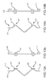
- FIGS. 11A-14B are certain illustrative brackets useful with the present invention.
- FIG. 1 there is shown a masonry veneer product 10 , illustrated schematically and described herein typically as a dry stack stone product body 12 , similar to a typical box material in appearance, such as the ABS Ledge Rock, Cultured Stone® County Ledge or other such Dry Stack ACMV products that are currently available commercially available.
- the new MVP and MVS have additional inventive features as described herein.
- the present invention could be applied to nearly any texture of manufactured stone or brick, but is primarily illustrated with a dry stack installation for the sake of simplicity (and as a representative installation).
- An embodiment of the present invention used with a grouted texture preferably includes a flange on one of the top and bottom of the stone and a second flange on either the left or right end, the flanges each serving as a ledge for a grouted joint.
- a flange on one of the top and bottom of the stone and a second flange on either the left or right end, the flanges each serving as a ledge for a grouted joint.
- One skilled in the art could modify the current design to utilize the present invention with other textures and configurations.
- FIG. 1 includes a pair of brackets 14 , 14 ′ embedded in the product body 12 .
- Each bracket includes a top end 16 and bottom end 18 .
- the top end 16 is illustrated as having a looped construction for receiving a fastener 40 as illustrated in FIG. 2A .
- the bottom end 18 preferably includes a curved shape 18 for nesting under an adjacent masonry veneer product (as illustrated on FIG. 3 ).
- FIGS. 11-14 illustrate certain embodiments of brackets useful with the present invention (the Figure “A” designation illustrating a side view and “B” designation illustrating a top view).
- the bracket 14 is embedded into the stone body 12 , with an intermediate portion 20 as shown in phantom in FIG. 2 .
- the intermediate portion is embedded in the product body 12 a depth sufficient to ensure adequate engagement to support the stone body 12 when attached to a building (not shown), preferably for the life of the building.
- the brackets 14 penetrate the stone body 12 to a depth D 1 that provides sufficient engagement between the bracket and cured concrete stone, but also which retains a thickness D 2 of concrete that will ensure the face of the stone body 12 does not expose the wire or fracture during the life of the building.
- the brackets 14 are preferably formed from a wire that is corrosion resistant, such as a stainless steel or galvanized steel, and having sufficient strength and sufficient stiffness to not deform and to provide the installation with an interference fit at the bottom as described below.
- the bracket 14 should be rigid enough to withstand handling, packaging, transport and installation without excessive deformation.
- the brackets 14 are formed from a fiberglass material, or any material known to one skilled in the art that is not corroded and will support the masonry product 10 .
- the brackets 14 are stamped from sheet metal or formed or molded from another non-corrosive material in a more flattened cross section.
- the product 10 may include water shedding feature, which is described herein to include a flashing lip 22 along the top surface 28 of the stone body 12 .
- This lip 22 is intended to inhibit the passage of moisture, such as wind driven rain, between the stone body 12 and an adjacent stone 10 ′ as illustrated in FIG. 3 .
- each stone body 12 may also include a corresponding recess 24 on the bottom surface 30 of the stone body 12 to correspond with the opposing lip 22 of the adjacent stone.
- This lip 22 and recess 24 also serve to obscure a view of the WRB installed beneath the stone to create a visually appealing dry stack installation. Additionally, the lip 22 may contact the body within the recess as illustrated in FIG.
- each stone preferably includes a lip 26 along one end of the stone body 12 , and a corresponding recess 27 along the opposite end of the stone body 12 , which will inhibit moisture intrusion, obscure visibility behind the product, and set the side to side gap.
- the lips 22 , 26 are illustrated in FIG. 1 as an angled or chamfered protrusion and recess, one skilled in the art appreciates that while not illustrated as such, the lips 22 , 26 could be simple ridge similar to that illustrated in FIG. 2 , a rabbet, shiplap as illustrated in FIG. 3 , or other type of configuration that provides a moisture block and an improved line of sight.
- the bracket 14 includes a first protrusion 34 formed in the bracket 14 .
- the protrusion extends below the back surface 32 of the stone body 12 to bear against the structure 39 and create an air gap G 1 under the product 10 when installed on a structure 39 as shown in FIG. 2 , preferably installed over a WRB 38 .
- the bracket 14 includes a bend 36 which holds the top end 16 away from the structure 39 and WRB 38 to create a second gap G 2 .
- FIG. 2 illustrates the bracket as being deformed to make the end 16 flat against the WRB 38 after the fastener 40 is installed.
- This force on the top end 16 acts as a lever, which as illustrated in FIG. 3 urges the opposite second end 18 of the bracket 14 away from the structure 39 and toward the back surface 32 ′ of a second body, such as an adjacent product 10 ′. Because the second end 18 is wedged below the lower product 10 ′, this causes a second protrusion 35 at the bottom end 18 to be held securely against the structure 39 and therefore the product is secured both at the top by the nail and at the bottom by a wedging action against the second product 10 ′.
- the top end of the bracket 14 does not have the bend 36 , and the bottom end 18 of the bracket is bent to lie in a plane above the back surface 32 of the stone body 12 as illustrated in FIG. 2 , so the bottom end 18 is installed under an adjacent product (not shown) simply using an interference fit.
- This interference may be at least 1 mm and could be 2, 3, 4, or 5 mm or more, depending on the stiffness of the bracket.
- the configuration of the bottom bracket illustrated in FIG. 2 may be used with or without the bent configuration of the top end 16 as illustrated in FIG. 2 .
- the second end 18 may be wedged against another body, such as a starter strip or an accessory, such as a ledge.
- a system including the product 10 described above includes a building structure 39 (such as a frame and sheathing or concrete structure), a weather resistant barrier installed over the structure (similar in nature and installation to that specified by the MVMA), a plurality of products 10 attached to the structure over the WRB 38 and attached to the structure 39 using fasteners 40 projecting through the brackets 14 .
- the fasteners 40 are preferably non-corrosive, such as galvanized roofing nails, screws or staples; provided however that the fasteners must provide sufficient strength to secure the product 10 to the structure 39 for the life of the structure.
- installation begins from the bottom of the building.
- a starter strip such as a J-channel
- the J-channel strip will align the bottom row of product in a straight line.
- a J-channel includes a recess to engage the bottom end 18 .
- the installer bends the bottom end e.g. as illustrated in FIG. 4 at 418 to position the hook close to the body for fitment into the J-channel (not shown).
- a corrosion resistant fastener 410 may then be used to secure the bottom end 418 , or the J-channel may sufficiently retain the bottom end 418 .
- a starter strip or weep screed should provide ventilation at the bottom, and therefore accommodations should be made to provide for air passage.
- the top row of the product may be capped or may extend to the soffit. In either event, it is desirable to include an air gap where possible to provide for air flow. Where water drainage does not permit this, MVMA details may be followed. Where the product extends to the soffit, an installation similar to typical brick installation may be performed, i.e. the soffit may be installed after the product is installed. Alternatively the soffit j-channel may include a spacer against the wall to provide for air flow at the top of the wall.
- a bead of caulk is optionally installed on the product along one of the top and bottom, plus one of the ends, so that the joint between adjacent products is filled with the caulk to provide a substantially effective water seal.
- a bead of caulk or foam dam is provided on the top or bottom and one end of each stone at the factory to provide a substantially watertight joint between adjacent products without a field-applied caulk.
- a grout product may optionally be installed between adjacent products for certain textures.
- a grout is preferably flexible, so that it can perform for an extended period without cracking.
- Such a grout is also preferably water resistant to minimize the amount of water that enters between adjacent products.
- a grout may be used with the flanged design described above.
- a bracket 514 optionally includes an integrally formed fastener.
- the top end 16 of the bracket 14 is formed in a manner such as illustrated in FIG. 5 and described below.
- the top end 516 of the bracket 516 has a pointed end 530 to penetrate the structure and hold the product 510 to the structure.
- the upper surface 535 of the top end 516 is struck with a hammer (not shown) to embed the pointed end 530 into the structure in a manner similar to a nail.
- the surface 532 of the end 516 includes a rough surface similar to a ring nail to improve retention.
- the end may have a loop similar to that shown in FIG. 1 at 16 to permanently secure the end 516 with a separate fastener such as a nail, screw or staple as described above.
- the building includes an insulation product on the outer surface of the building, such as a foam board 546 .
- an insulation product on the outer surface of the building, such as a foam board 546 .
- the stone is installed over a foam board 546 , and the pointed end 530 of the bracket 516 penetrates the foam board 546 and rests against the outer surface 542 ′ of the structure.
- a fastener is driven through a loop formed on the bracket 516 ′ as described above with reference to FIG. 1 . In this manner, the gap G 1 ′ is maintained between the product 510 ′ and the foam board 546 to enable any moisture to escape, without the projection 534 crushing the upper surface 544 ′ of the foam board 546 .
- FIGS. 13 A and 13 B illustrate an embodiment of a bracket 514 ′ prior to being imbedded into a product (not shown).
- FIG. 13 A illustrates a side view
- FIG. 13B illustrates a side view of the bracket of this embodiment.
- the illustrated bracket 514 ′ is particularly useful for installation over a softer material, such as insulation (in a manner similar to that illustrated in FIG. 5A ), but without the bracket 514 ′ having a pointed end (as shown in FIGS. 5 and 5A at 530 , 530 ′).
- the bracket 514 ′ does not project through the foam board (not shown).
- the bracket 514 ′ includes a pair of lands 537 at the projections 534 ′ to bear against the soft material (or the structure).
- the lands may comprise a flat portion of the baracket 514 ′, such as a washer or other flat piece welded or otherwise attached to the bracket 514 ′
- the bracket 514 ′′ includes a pair of lands 537 ′ integrally formed in the bracket 514 ′′ in the form of coils. These lands 537 ′ are similarly formed at the projections 537 ′ so the lands bear against a softer material or the building structure (not shown). This lands 537 and 537 ′ enable the bracket 514 ′ and 514 ′′ to rest against the foam (not shown), and the gap illustrated in FIG.
- the brackets 514 ′ and 514 ′′ each includes an end 518 ′ and 518 ′′, respectively, with and aperture for a fastener to secure the top end of the bracket 516 .
- land 537 and 537 ′ may include an aperture for a fastener.
- lands may be formed in, or attached to the brackets as appropriate to the particular design.
- the product 610 includes brackets as described above with reference to FIG. 1 , but a fastener 640 , such as a nail or screw, is optionally installed through the loop 630 formed in the bracket 614 and shipped with the product.
- the fastener 640 is held by an interference fit to the inside of the loop 630 .
- the fastener 640 is adhered, tack welded, or otherwise temporarily or permanently secured to the bracket 614 .
- the installer simply needs to carry a tool to secure the fastener 640 , such as a hammer or screwdriver (depending on the fastener provided).
- the product 10 preferably includes at least two brackets 14 , 14 ′.
- brackets 14 , 14 ′ One skilled in the art appreciates that more than two brackets may be utilized to provide additional support and attachment.
- the nature of the product (size, weight) and the nature of the brackets, fasteners and structure and environment can affect these requirements. In the event a product must be cut to length, care should be taken to leave enough concrete remains to retain the bracket permanently. If the installer anticipates a bracket must be removed, the installer should consider finding a shorter product to avoid cutting the bracket or cutting the product. Alternatively, where required, the installer may cut both ends of a product to achieve the desired length while leaving both brackets intact.
- an installer may choose to cut the end(s) of more than one stone to ensure all brackets are retained.
- a product made according to the present invention may be cut in a conventional manner typically used to cut concrete, such as a Cultured Clean Cut (reference culturedcleancut.com), a masonry saw, grinder, hammer & chisel, guillotine cutter, and the like.
- a new bracket is secured to the product 10 by either adhering or fastening a new bracket (such as a stamped metal bracket) to the back surface 32 of the product 10 .
- This may be done with adhesive or using fasteners (such as Tapcon® screws into holes drilled into the back surface 32 of the product 10 ).
- fasteners such as Tapcon® screws into holes drilled into the back surface 32 of the product 10 .
- the present invention may be used in other applications, such as slate or composite roofing.
- brackets may be adhered in a similar fashion to natural stone or roofing products (such as slate). With roofing products, it is anticipated the products will be shingled, so the length of the protrusions 34 , 35 must be adjusted to provide for such shingling of the roofing product.
- composite articles may have the brackets molded into the product.
- the invention is also applied to corners and accessories, such as trim stones, keystones, ledges, light fixtures, outlets, column wraps and other products.
- corners in one embodiment, only one side of the stone corners are attached to the structure, and a spacer is provided on the backside of the return to provide a consistent air gap and exterior thickness.
- the installation instructions teach the installer to set a gap manually, or to use separate spacers, such as foam or molded parts.
- the instant invention is applied to a panelized product. In such a case, it may be necessary to utilize a greater number of brackets to adequately support and secure the panelized product due to its size and weight.
- bracket ends are utilized. While the brackets illustrated in the Figs are unitary; i.e. both ends 16 , 18 are formed from the same piece of wire as is the intermediate portion 20 , and while the following is not illustrated here, one skilled in the art appreciates that the bracket 14 could comprise two discrete ends 16 , 18 each having an opposite end embedded in the concrete and having substantially no intermediate portion 20 .
- the bracket 14 when installing the product over concrete, one should install the WRB as suggested by the MVMA and secure the product of the present invention through the WRB and directly to the block with appropriate fasteners, thus eliminating the need to ensure a secure chemical bond to the concrete block as required with ACMV products.
- the instant invention may be used in interior and other applications. In certain applications, the air gap may not be required (e.g. a dry interior application), and therefore the gap G 1 may not be necessary and one skilled in the art will adapt the product accordingly.
- One embodiment of the present invention is applied to individual stones or bricks. This makes installation simple, as fewer products will be cut and less scrap created. Furthermore, it avoids the potential that an installer will align the panels to create unsightly lines or an unattractive panelized wall. Additionally, the individual products also make it simpler to create accessory products that are compatible with this system. As noted above, however, applicant envisions that a panelized system could utilize the present invention, either alone or in combination with the individual products as described above.
Abstract
Description
Claims (16)
Priority Applications (4)
| Application Number | Priority Date | Filing Date | Title |
|---|---|---|---|
| US13/420,143 US9587398B1 (en) | 2011-03-16 | 2012-03-14 | Building veneer system |
| US14/516,572 US9677283B2 (en) | 2011-03-16 | 2014-10-16 | Building veneer system |
| US15/449,525 US9803371B2 (en) | 2011-03-16 | 2017-03-03 | Building veneer system |
| US15/619,872 US10024062B2 (en) | 2011-03-16 | 2017-06-12 | Building veneer system |
Applications Claiming Priority (2)
| Application Number | Priority Date | Filing Date | Title |
|---|---|---|---|
| US201161453498P | 2011-03-16 | 2011-03-16 | |
| US13/420,143 US9587398B1 (en) | 2011-03-16 | 2012-03-14 | Building veneer system |
Related Child Applications (2)
| Application Number | Title | Priority Date | Filing Date |
|---|---|---|---|
| US14/516,572 Continuation-In-Part US9677283B2 (en) | 2011-03-16 | 2014-10-16 | Building veneer system |
| US15/449,525 Continuation US9803371B2 (en) | 2011-03-16 | 2017-03-03 | Building veneer system |
Publications (1)
| Publication Number | Publication Date |
|---|---|
| US9587398B1 true US9587398B1 (en) | 2017-03-07 |
Family
ID=58162188
Family Applications (3)
| Application Number | Title | Priority Date | Filing Date |
|---|---|---|---|
| US13/420,143 Active US9587398B1 (en) | 2011-03-16 | 2012-03-14 | Building veneer system |
| US15/449,525 Active US9803371B2 (en) | 2011-03-16 | 2017-03-03 | Building veneer system |
| US15/619,872 Active US10024062B2 (en) | 2011-03-16 | 2017-06-12 | Building veneer system |
Family Applications After (2)
| Application Number | Title | Priority Date | Filing Date |
|---|---|---|---|
| US15/449,525 Active US9803371B2 (en) | 2011-03-16 | 2017-03-03 | Building veneer system |
| US15/619,872 Active US10024062B2 (en) | 2011-03-16 | 2017-06-12 | Building veneer system |
Country Status (1)
| Country | Link |
|---|---|
| US (3) | US9587398B1 (en) |
Cited By (3)
| Publication number | Priority date | Publication date | Assignee | Title |
|---|---|---|---|---|
| US10927552B2 (en) | 2019-02-15 | 2021-02-23 | Stone Creek Products, LLC | Veneer panel and veneer corner with mounting systems |
| US11447959B2 (en) * | 2019-05-21 | 2022-09-20 | Orcutt Innovations, Llc | Masonry veneer hanger and spacer |
| US20230235570A1 (en) * | 2022-01-19 | 2023-07-27 | David R. Orcutt | Masonry veneer hanger and spacer |
Families Citing this family (4)
| Publication number | Priority date | Publication date | Assignee | Title |
|---|---|---|---|---|
| US9267295B2 (en) * | 2010-07-09 | 2016-02-23 | Matthew Mann | Suspension rails for panel veneer systems |
| US10753101B1 (en) * | 2016-12-09 | 2020-08-25 | Baton, LLC | Artificial lightweight stone |
| US9957723B1 (en) * | 2017-09-29 | 2018-05-01 | Ryan W. Collison | Mortarless stone veneer |
| WO2021211491A1 (en) * | 2020-04-13 | 2021-10-21 | Simonsen David | Continuous insulation mounting system |
Citations (118)
| Publication number | Priority date | Publication date | Assignee | Title |
|---|---|---|---|---|
| US495572A (en) | 1893-04-18 | Paul warnstorf | ||
| US663770A (en) | 1899-02-20 | 1900-12-11 | Josephine Marie Louise Messerli | Fumigating device. |
| US2011510A (en) * | 1934-09-27 | 1935-08-13 | O W Ketcham | Building construction |
| US2823399A (en) | 1954-07-21 | 1958-02-18 | Harold A Stewart | Painting accessories |
| US2924963A (en) | 1955-04-07 | 1960-02-16 | Structural Clay Products Res F | Method and means for veneer brick |
| US3142938A (en) | 1963-10-11 | 1964-08-04 | Elwood L Eberhardt | Wall structure |
| US3277764A (en) | 1964-09-09 | 1966-10-11 | Edward V Hene | Apparatus for working corrugated board or the like |
| US3377764A (en) | 1966-04-26 | 1968-04-16 | Storch Bernard | Anchoring means for masonry walls |
| US3533206A (en) * | 1968-07-16 | 1970-10-13 | James K Passeno Jr | Building block holder for fabricating veneer walls |
| US3621625A (en) * | 1970-08-17 | 1971-11-23 | Robert S Medow | Brick siding |
| US3964226A (en) | 1974-09-27 | 1976-06-22 | Hohmann & Barnard, Inc. | Adjustable wall-tie reinforcing system |
| US4160346A (en) | 1976-05-11 | 1979-07-10 | Global Coatings Limited | Roof coating composition and construction |
| US4386136A (en) | 1976-05-11 | 1983-05-31 | Global Coatings Limited | Roof coating composition and construction |
| US4765115A (en) | 1987-05-27 | 1988-08-23 | Pollina Peter J | Brick supporting structures |
| US4819401A (en) | 1988-04-08 | 1989-04-11 | Whitney Jr G Ward | Wire anchor for metal stud/brick veneer wall construction |
| US4843776A (en) | 1988-07-19 | 1989-07-04 | Alvin Guignard | Brick tie |
| US4852320A (en) | 1988-04-19 | 1989-08-01 | Ballantyne Brian R | Mortar collecting device for use in masonry wall construction |
| US4869038A (en) | 1987-10-19 | 1989-09-26 | Dur-O-Wall Inc. | Veneer wall anchor system |
| US4992005A (en) * | 1990-01-09 | 1991-02-12 | Hilfiker William K | Lifting device and method for retaining wall panels |
| US5062913A (en) | 1988-04-05 | 1991-11-05 | Charles R. Owens | Laminated tile product and method for producing the same |
| US5208086A (en) | 1988-04-05 | 1993-05-04 | Owens Charles R | Laminated tile product, method for producing the same and method for installing the same |
| US5228937A (en) | 1991-04-03 | 1993-07-20 | National Brick Panel Systems, Inc. | Method of making a brick panel |
| US5265396A (en) * | 1990-10-26 | 1993-11-30 | Inax Corporation | Construction method of boardlike building elements |
| US5314554A (en) | 1988-04-05 | 1994-05-24 | Owens Charles R | Method for producing a laminated tile product |
| US5373676A (en) | 1992-09-28 | 1994-12-20 | Francis; Steven R. | Thin brick panel assembly |
| US5392581A (en) | 1993-11-08 | 1995-02-28 | Fero Holdings Ltd. | Masonry connector |
| US5454200A (en) | 1993-11-04 | 1995-10-03 | Hohmann; Ronald P. | Veneer anchoring system |
| US5490366A (en) | 1994-11-24 | 1996-02-13 | Burns; William S. | Adjustable wall tie |
| US5501049A (en) | 1992-09-28 | 1996-03-26 | Francis; Steven R. | Thin brick panel assembly |
| US5555690A (en) | 1990-04-24 | 1996-09-17 | Cosentino; Edward | Tile mounting system |
| US5634307A (en) | 1991-10-11 | 1997-06-03 | Larriberot; Jean-Paul | Imitation stone surface apparatus and method |
| US5634310A (en) | 1993-11-04 | 1997-06-03 | Hohmann & Barnard, Inc. | Surface-mounted veneer anchor |
| US5671578A (en) | 1995-04-24 | 1997-09-30 | Hohmann & Barnard, Inc. | Surface-mounted veneer anchor for seismic construction system |
| US5816008A (en) | 1997-06-02 | 1998-10-06 | Hohmann & Barnard, Inc. | T-head, brick veneer anchor |
| US5836572A (en) | 1994-12-30 | 1998-11-17 | Toyo Exterior Co., Ltd. | Method for constructing an outdoor structure such as a gate post, gate wing, or fence |
| US6164029A (en) | 1998-09-17 | 2000-12-26 | Lee; Yu-Hong | Slabstone positioning device |
| US6170214B1 (en) | 1998-06-09 | 2001-01-09 | Kenneth Treister | Cladding system |
| US6209281B1 (en) | 1998-01-30 | 2001-04-03 | Bailey Metal Products Limited | Brick tie anchor |
| US6279283B1 (en) | 2000-04-12 | 2001-08-28 | Hohmann & Barnard, Inc. | Low-profile wall tie |
| US6315489B1 (en) | 1998-11-30 | 2001-11-13 | Nichiha Corporation | Fastening member |
| US20010054270A1 (en) | 1998-01-30 | 2001-12-27 | John Rice | Brick tie anchor |
| US6351922B1 (en) | 2000-11-20 | 2002-03-05 | Blok-Lok Limited | Single-end wall tie |
| US20020046536A1 (en) | 2000-08-22 | 2002-04-25 | Nichiha Co., Ltd. | Fastening member and siding boards attachment structure |
| US20030066259A1 (en) | 2001-09-10 | 2003-04-10 | Sudweeks Dan L. | Fastener system and method for attaching manufactured brick or stone to a surface |
| US6615560B2 (en) | 2000-06-30 | 2003-09-09 | Nichiha Co., Ltd. | Siding boards attachment structure, sealing member used for the same, siding board, and method of attaching siding boards |
| US20030213212A1 (en) | 2002-05-20 | 2003-11-20 | Passeno James Kenneth | Method and apparatus for making thin brick wall facing |
| US6668505B1 (en) | 2002-09-03 | 2003-12-30 | Hohmann & Barnard, Inc. | High-span anchors and reinforcements for masonry walls |
| US20040040239A1 (en) | 2002-08-28 | 2004-03-04 | Paul Baillargeon | Prefabricated thin wall concrete panel |
| US6789365B1 (en) | 2002-11-13 | 2004-09-14 | Hohmann & Barnard, Inc. | Side-welded anchors and reinforcements for masonry walls |
| US20040216408A1 (en) | 2003-04-30 | 2004-11-04 | Hohmann & Barnard, Inc. | High-strength surface-mounted anchors and wall anchor systems using the same |
| US6830405B2 (en) | 2000-05-29 | 2004-12-14 | Nichiha Corporation | Fastening member |
| US6851239B1 (en) | 2002-11-20 | 2005-02-08 | Hohmann & Barnard, Inc. | True-joint anchoring systems for cavity walls |
| US20050087908A1 (en) | 2003-10-24 | 2005-04-28 | Moe Nasr | Simulated stone and masonry and brick textured siding panels |
| US20050102944A1 (en) | 2003-10-31 | 2005-05-19 | Nichiha Corporation | Fastening member and siding boards attachment structure using the fastening member |
| US6913645B2 (en) | 2001-07-23 | 2005-07-05 | Mcnulty, Jr. William J. | Cementitious material |
| US20050188642A1 (en) * | 2004-02-13 | 2005-09-01 | Rinox Inc. | Decorative brick facade module for walls |
| US6941717B2 (en) | 2003-05-01 | 2005-09-13 | Hohmann & Barnard, Inc. | Wall anchor constructs and surface-mounted anchoring systems utilizing the same |
| USD510146S1 (en) | 2004-02-17 | 2005-09-27 | Attebery Ii Harold C | Masonry tile |
| US20050210811A1 (en) * | 2004-02-17 | 2005-09-29 | Nasvik Paul C | Precast concrete veneer panel system |
| US20050217192A1 (en) | 2004-03-31 | 2005-10-06 | Moshe Boosy | High end mosaic tile production |
| US20060005490A1 (en) | 2003-04-30 | 2006-01-12 | Hohmann & Barnard, Inc. | Notched surface-mounted anchors and wall anchor systems using the same |
| US20060026919A1 (en) | 2004-07-16 | 2006-02-09 | Cerainteed Corporation | Imitation stone siding system |
| US7017318B1 (en) | 2002-07-03 | 2006-03-28 | Hohmann & Barnard, Inc. | High-span anchoring system for cavity walls |
| USRE39091E1 (en) | 1996-02-15 | 2006-05-09 | Stonetile (Canada) Ltd. | Concrete panel construction |
| US20060101752A1 (en) | 2002-07-15 | 2006-05-18 | Mieko Sakai | Artificial stone wall panel |
| US20060265988A1 (en) | 2005-05-31 | 2006-11-30 | Kubota Matsushitadenko Exterior Works, Ltd. | Wall materials bracket and insulating wall structure |
| US20060272261A1 (en) | 2005-03-22 | 2006-12-07 | Nichiha Co., Ltd. | Member and structure for fastening exterior panel |
| US7159367B1 (en) | 2001-08-06 | 2007-01-09 | John King | Simulated masonry garden walls having modular construction |
| US20070045897A1 (en) | 2005-08-23 | 2007-03-01 | Cliff Alexander | Plastic tray for manufacturing a simulated stone product |
| US20070062138A1 (en) | 2005-09-21 | 2007-03-22 | The Eci Group, Llc | Veneer anchoring system |
| US20070078191A1 (en) | 2005-09-30 | 2007-04-05 | Guhde Brian J | Foamed reinforced composite siding product |
| US7225590B1 (en) | 2003-07-14 | 2007-06-05 | The Steel Network, Inc. | Brick tie |
| US20070130860A1 (en) | 2005-12-09 | 2007-06-14 | Les Pierres Stonedge Inc. | Artificial stone anchoring system and method |
| US20070209308A1 (en) | 2004-07-30 | 2007-09-13 | James Barrett | Faux-stone architectural panel system |
| US7325366B1 (en) | 2005-08-08 | 2008-02-05 | Hohmann & Barnard, Inc. | Snap-in wire tie |
| US20080141605A1 (en) | 2006-12-14 | 2008-06-19 | Hohmann & Barnard, Inc. | Dual seal anchoring systems for insulated cavity walls |
| US20080155922A1 (en) | 2006-12-29 | 2008-07-03 | Wolf David H | Panelized veneer with backer-to-backer locators |
| US20080155921A1 (en) | 2006-12-29 | 2008-07-03 | Wolf David H | Veneer panel |
| US20090094914A1 (en) | 2007-10-10 | 2009-04-16 | Tecton Products, Llc | Pultruded building product |
| US20090133357A1 (en) | 2007-11-28 | 2009-05-28 | Richards Joseph P | Composite fastener, belly nut, tie system and/or method for reducing heat transfer through a building envelope |
| US20090193742A1 (en) * | 2008-02-06 | 2009-08-06 | Wolf David H | Prefabricated wall panel with tongue and groove construction |
| US20090241451A1 (en) | 2008-04-01 | 2009-10-01 | Griffiths Robert T | Wall panel system with insert |
| US7736096B1 (en) * | 2007-09-24 | 2010-06-15 | Aaron Albert E | Modular interlocking retaining wall/seawall having reduced installation time |
| US20100257803A1 (en) | 2009-04-10 | 2010-10-14 | Mitek Holdings, Inc. | Wind load anchors and high-wind anchoring systems for cavity walls |
| US20110047919A1 (en) | 2009-09-03 | 2011-03-03 | Mitek Holdings, Inc. | Thermally isolated anchoring system |
| US20110061333A1 (en) | 2009-09-11 | 2011-03-17 | Joseph Bronner | Twist On Wire Tie Wall Connection System And Method |
| US20110094176A1 (en) | 2009-10-27 | 2011-04-28 | Joseph Bronner | Winged Anchor and Spiked Spacer for Veneer Wall Tie Connection System and Method |
| US20110146195A1 (en) | 2009-12-17 | 2011-06-23 | Mitek Holdings, Inc. | Rubble stone anchoring system |
| US20110175255A1 (en) | 2010-01-18 | 2011-07-21 | Boral Stone Products LLC. | Method of retaining nail strip during a siding mold process |
| US20110173902A1 (en) | 2010-01-15 | 2011-07-21 | Mitek Holdings, Inc. | Anchor System for Composite Panel |
| US8033069B2 (en) * | 2008-05-01 | 2011-10-11 | United States Gypsum Company | Embedded clip attachment for cast architectural element |
| US20110277397A1 (en) | 2010-05-11 | 2011-11-17 | Mitek Holdings, Inc. | Restoration Anchoring System |
| US8122663B1 (en) | 2004-09-10 | 2012-02-28 | Mitek Holdings, Inc. | Anchors and reinforcements for masonry walls |
| US8151530B2 (en) | 2009-07-29 | 2012-04-10 | Exteria Building Products, Llc | Simulated masonry wall panel with improved interlock system |
| US20120241574A1 (en) | 2009-09-30 | 2012-09-27 | Masaki Uota | External material clamp and external material clamping structure |
| US20120304576A1 (en) | 2011-05-31 | 2012-12-06 | Mitek Holdings, Inc. | Dual seal tubular anchor for cavity walls |
| US8387323B2 (en) | 2007-11-02 | 2013-03-05 | Silvermine Stone Company | Artificial stone siding product |
| US20130074442A1 (en) | 2011-09-23 | 2013-03-28 | Mitek Holdings, Inc. | High-strength pintles and anchoring systems utilizing the same |
| US20130232893A1 (en) | 2012-03-08 | 2013-09-12 | Mitek Holdings, Inc. | Backup wall reinforcement with t-type siderail |
| US20130232909A1 (en) | 2012-02-23 | 2013-09-12 | Heckmann Building Products Inc. | Thermal clip attachment apparatus for masonry anchors and methods thereof |
| US20130247484A1 (en) | 2012-03-21 | 2013-09-26 | Mitek Holdings, Inc. | Backup wall reinforcement with t-type anchor |
| US20130247498A1 (en) | 2012-03-21 | 2013-09-26 | Mitek Holdings, Inc. | L-shaped sheetmetal anchor with tubular leg and anchoring assembly |
| US20130247483A1 (en) | 2012-03-21 | 2013-09-26 | Mitek Holdings, Inc. | Thermally-isolated anchoring systems for cavity walls |
| US20130340378A1 (en) | 2012-06-22 | 2013-12-26 | Mitek Holdings, Inc. | Anchor with angular adjustment |
| US20140000211A1 (en) | 2012-06-28 | 2014-01-02 | Mitek Holdings, Inc. | Low profile pullout resistant pintle and anchoring system utilizing the same |
| US20140041331A1 (en) | 2012-08-08 | 2014-02-13 | Boral Stone Products Llc | Universal corner panel |
| US8667757B1 (en) | 2013-03-11 | 2014-03-11 | Mitek Holdings, Inc. | Veneer tie and wall anchoring systems with in-cavity thermal breaks |
| US20140075855A1 (en) | 2012-09-15 | 2014-03-20 | Mitek Holdings, Inc. | High-strength veneer tie and thermally isolated anchoring systems utilizing the same |
| US20140075856A1 (en) | 2012-09-15 | 2014-03-20 | Mitek Holdings, Inc. | Pullout resistant pintle and anchoring system utilizing the same |
| US8726596B2 (en) | 2012-03-21 | 2014-05-20 | Mitek Holdings, Inc. | High-strength partially compressed veneer ties and anchoring systems utilizing the same |
| US8833003B1 (en) | 2013-03-12 | 2014-09-16 | Columbia Insurance Company | High-strength rectangular wire veneer tie and anchoring systems utilizing the same |
| US20140260051A1 (en) | 2013-03-13 | 2014-09-18 | Mitek Holdings, Inc. | Thermally isolated anchoring system |
| US20140260040A1 (en) | 2013-03-14 | 2014-09-18 | Mitek Holdings, Inc. | Fail-safe anchoring systems for cavity walls |
| US20140260033A1 (en) | 2013-03-13 | 2014-09-18 | Mitek Holdings, Inc. | Channel Anchor with Insulation Holder and Anchoring System Using the Same |
| US20140311071A1 (en) | 2013-02-25 | 2014-10-23 | Heckmann Building Products Inc. | Masonry Wall Wire Reinforcement Apparatus and Methods Thereof |
| US9021767B1 (en) * | 2013-12-18 | 2015-05-05 | Ply Gem Industries, Inc. | Apparatus and kit for stone veneer panel installation |
| US9249579B2 (en) * | 2013-12-18 | 2016-02-02 | Ply Gem Industries, Inc. | Kit for stone veneer panel installation |
| US20160108623A1 (en) | 2011-03-16 | 2016-04-21 | Talus Systems, LLC | Building Veneer System |
Family Cites Families (15)
| Publication number | Priority date | Publication date | Assignee | Title |
|---|---|---|---|---|
| US1946732A (en) | 1931-04-11 | 1934-02-13 | Daniel B Danielson | Veneer and backing bond and anchor |
| US2528205A (en) * | 1946-07-15 | 1950-10-31 | Giuseppe S Benevento | Brick veneer and clip |
| US3277626A (en) | 1963-10-17 | 1966-10-11 | Dur O Wal National Inc | Double shank adjustable wall tie |
| JPH0663337B2 (en) * | 1987-03-05 | 1994-08-22 | 元旦ビユーティ工業株式会社 | Tile block exterior wall |
| US4953337A (en) | 1987-12-08 | 1990-09-04 | Mills Ronald L | Method and apparatus for constructing a masonry structure |
| US4866896A (en) * | 1988-04-26 | 1989-09-19 | Construction Specialties, Inc. | Panel wall system |
| US4987712A (en) * | 1989-05-17 | 1991-01-29 | Empire Brick Pty. Limited | Brick cladding assembly |
| AU4081093A (en) * | 1992-05-18 | 1993-12-13 | Israel Erlanger | A system for stone cladding of buildings |
| US20070119109A1 (en) | 2005-11-25 | 2007-05-31 | Peter Kuelker | Precast panel mounting system |
| US20080155938A1 (en) * | 2006-12-29 | 2008-07-03 | Attebery Harold C | Fiber reinforced concrete stone panel system |
| US20080196354A1 (en) * | 2007-02-21 | 2008-08-21 | Attebery Harold C | Fiber Reinforced Concrete Exterior Wall System |
| US20080196336A1 (en) * | 2007-02-21 | 2008-08-21 | Attebery Harold C | Fiber reinforced concrete exterior wall system |
| US8418422B2 (en) | 2011-01-21 | 2013-04-16 | Masonry Reinforcing Corporation Of America | Wall anchoring device and method |
| US8596010B2 (en) | 2011-05-20 | 2013-12-03 | Mitek Holdings, Inc. | Anchor with angular adjustment |
| US8733049B2 (en) | 2011-09-23 | 2014-05-27 | Mitek Holdings, Inc. | Dual pintle and anchoring system utilizing the same |
-
2012
- 2012-03-14 US US13/420,143 patent/US9587398B1/en active Active
-
2017
- 2017-03-03 US US15/449,525 patent/US9803371B2/en active Active
- 2017-06-12 US US15/619,872 patent/US10024062B2/en active Active
Patent Citations (122)
| Publication number | Priority date | Publication date | Assignee | Title |
|---|---|---|---|---|
| US495572A (en) | 1893-04-18 | Paul warnstorf | ||
| US663770A (en) | 1899-02-20 | 1900-12-11 | Josephine Marie Louise Messerli | Fumigating device. |
| US2011510A (en) * | 1934-09-27 | 1935-08-13 | O W Ketcham | Building construction |
| US2823399A (en) | 1954-07-21 | 1958-02-18 | Harold A Stewart | Painting accessories |
| US2924963A (en) | 1955-04-07 | 1960-02-16 | Structural Clay Products Res F | Method and means for veneer brick |
| US3142938A (en) | 1963-10-11 | 1964-08-04 | Elwood L Eberhardt | Wall structure |
| US3277764A (en) | 1964-09-09 | 1966-10-11 | Edward V Hene | Apparatus for working corrugated board or the like |
| US3377764A (en) | 1966-04-26 | 1968-04-16 | Storch Bernard | Anchoring means for masonry walls |
| US3533206A (en) * | 1968-07-16 | 1970-10-13 | James K Passeno Jr | Building block holder for fabricating veneer walls |
| US3621625A (en) * | 1970-08-17 | 1971-11-23 | Robert S Medow | Brick siding |
| US3964226A (en) | 1974-09-27 | 1976-06-22 | Hohmann & Barnard, Inc. | Adjustable wall-tie reinforcing system |
| US4251578A (en) | 1976-05-11 | 1981-02-17 | Global Coatings Limited | Roof coating composition and construction |
| US4287241A (en) | 1976-05-11 | 1981-09-01 | Global Coatings Limited | Roof coating composition and construction |
| US4386136A (en) | 1976-05-11 | 1983-05-31 | Global Coatings Limited | Roof coating composition and construction |
| US4160346A (en) | 1976-05-11 | 1979-07-10 | Global Coatings Limited | Roof coating composition and construction |
| US4765115A (en) | 1987-05-27 | 1988-08-23 | Pollina Peter J | Brick supporting structures |
| US4869038A (en) | 1987-10-19 | 1989-09-26 | Dur-O-Wall Inc. | Veneer wall anchor system |
| US5062913A (en) | 1988-04-05 | 1991-11-05 | Charles R. Owens | Laminated tile product and method for producing the same |
| US5208086A (en) | 1988-04-05 | 1993-05-04 | Owens Charles R | Laminated tile product, method for producing the same and method for installing the same |
| US5314554A (en) | 1988-04-05 | 1994-05-24 | Owens Charles R | Method for producing a laminated tile product |
| US4819401A (en) | 1988-04-08 | 1989-04-11 | Whitney Jr G Ward | Wire anchor for metal stud/brick veneer wall construction |
| US4852320A (en) | 1988-04-19 | 1989-08-01 | Ballantyne Brian R | Mortar collecting device for use in masonry wall construction |
| US4843776A (en) | 1988-07-19 | 1989-07-04 | Alvin Guignard | Brick tie |
| US4992005A (en) * | 1990-01-09 | 1991-02-12 | Hilfiker William K | Lifting device and method for retaining wall panels |
| US5555690A (en) | 1990-04-24 | 1996-09-17 | Cosentino; Edward | Tile mounting system |
| US5265396A (en) * | 1990-10-26 | 1993-11-30 | Inax Corporation | Construction method of boardlike building elements |
| US5228937A (en) | 1991-04-03 | 1993-07-20 | National Brick Panel Systems, Inc. | Method of making a brick panel |
| US5634307A (en) | 1991-10-11 | 1997-06-03 | Larriberot; Jean-Paul | Imitation stone surface apparatus and method |
| US5501049A (en) | 1992-09-28 | 1996-03-26 | Francis; Steven R. | Thin brick panel assembly |
| US5373676A (en) | 1992-09-28 | 1994-12-20 | Francis; Steven R. | Thin brick panel assembly |
| US5454200A (en) | 1993-11-04 | 1995-10-03 | Hohmann; Ronald P. | Veneer anchoring system |
| US5634310A (en) | 1993-11-04 | 1997-06-03 | Hohmann & Barnard, Inc. | Surface-mounted veneer anchor |
| US5392581A (en) | 1993-11-08 | 1995-02-28 | Fero Holdings Ltd. | Masonry connector |
| US5490366A (en) | 1994-11-24 | 1996-02-13 | Burns; William S. | Adjustable wall tie |
| US5836572A (en) | 1994-12-30 | 1998-11-17 | Toyo Exterior Co., Ltd. | Method for constructing an outdoor structure such as a gate post, gate wing, or fence |
| US5671578A (en) | 1995-04-24 | 1997-09-30 | Hohmann & Barnard, Inc. | Surface-mounted veneer anchor for seismic construction system |
| USRE39091E1 (en) | 1996-02-15 | 2006-05-09 | Stonetile (Canada) Ltd. | Concrete panel construction |
| US5816008A (en) | 1997-06-02 | 1998-10-06 | Hohmann & Barnard, Inc. | T-head, brick veneer anchor |
| US6209281B1 (en) | 1998-01-30 | 2001-04-03 | Bailey Metal Products Limited | Brick tie anchor |
| US20010054270A1 (en) | 1998-01-30 | 2001-12-27 | John Rice | Brick tie anchor |
| US6170214B1 (en) | 1998-06-09 | 2001-01-09 | Kenneth Treister | Cladding system |
| US6164029A (en) | 1998-09-17 | 2000-12-26 | Lee; Yu-Hong | Slabstone positioning device |
| US6315489B1 (en) | 1998-11-30 | 2001-11-13 | Nichiha Corporation | Fastening member |
| US6279283B1 (en) | 2000-04-12 | 2001-08-28 | Hohmann & Barnard, Inc. | Low-profile wall tie |
| US6830405B2 (en) | 2000-05-29 | 2004-12-14 | Nichiha Corporation | Fastening member |
| US6615560B2 (en) | 2000-06-30 | 2003-09-09 | Nichiha Co., Ltd. | Siding boards attachment structure, sealing member used for the same, siding board, and method of attaching siding boards |
| US20020046536A1 (en) | 2000-08-22 | 2002-04-25 | Nichiha Co., Ltd. | Fastening member and siding boards attachment structure |
| US6351922B1 (en) | 2000-11-20 | 2002-03-05 | Blok-Lok Limited | Single-end wall tie |
| US6913645B2 (en) | 2001-07-23 | 2005-07-05 | Mcnulty, Jr. William J. | Cementitious material |
| US7159367B1 (en) | 2001-08-06 | 2007-01-09 | John King | Simulated masonry garden walls having modular construction |
| US20030066259A1 (en) | 2001-09-10 | 2003-04-10 | Sudweeks Dan L. | Fastener system and method for attaching manufactured brick or stone to a surface |
| US20030213212A1 (en) | 2002-05-20 | 2003-11-20 | Passeno James Kenneth | Method and apparatus for making thin brick wall facing |
| US7017318B1 (en) | 2002-07-03 | 2006-03-28 | Hohmann & Barnard, Inc. | High-span anchoring system for cavity walls |
| US20060101752A1 (en) | 2002-07-15 | 2006-05-18 | Mieko Sakai | Artificial stone wall panel |
| US20040040239A1 (en) | 2002-08-28 | 2004-03-04 | Paul Baillargeon | Prefabricated thin wall concrete panel |
| US6668505B1 (en) | 2002-09-03 | 2003-12-30 | Hohmann & Barnard, Inc. | High-span anchors and reinforcements for masonry walls |
| US6789365B1 (en) | 2002-11-13 | 2004-09-14 | Hohmann & Barnard, Inc. | Side-welded anchors and reinforcements for masonry walls |
| US6851239B1 (en) | 2002-11-20 | 2005-02-08 | Hohmann & Barnard, Inc. | True-joint anchoring systems for cavity walls |
| US20040216408A1 (en) | 2003-04-30 | 2004-11-04 | Hohmann & Barnard, Inc. | High-strength surface-mounted anchors and wall anchor systems using the same |
| US20060005490A1 (en) | 2003-04-30 | 2006-01-12 | Hohmann & Barnard, Inc. | Notched surface-mounted anchors and wall anchor systems using the same |
| US6941717B2 (en) | 2003-05-01 | 2005-09-13 | Hohmann & Barnard, Inc. | Wall anchor constructs and surface-mounted anchoring systems utilizing the same |
| US7225590B1 (en) | 2003-07-14 | 2007-06-05 | The Steel Network, Inc. | Brick tie |
| US20050087908A1 (en) | 2003-10-24 | 2005-04-28 | Moe Nasr | Simulated stone and masonry and brick textured siding panels |
| US20050102944A1 (en) | 2003-10-31 | 2005-05-19 | Nichiha Corporation | Fastening member and siding boards attachment structure using the fastening member |
| US20050188642A1 (en) * | 2004-02-13 | 2005-09-01 | Rinox Inc. | Decorative brick facade module for walls |
| US20050210811A1 (en) * | 2004-02-17 | 2005-09-29 | Nasvik Paul C | Precast concrete veneer panel system |
| USD510146S1 (en) | 2004-02-17 | 2005-09-27 | Attebery Ii Harold C | Masonry tile |
| US20050217192A1 (en) | 2004-03-31 | 2005-10-06 | Moshe Boosy | High end mosaic tile production |
| US20060026919A1 (en) | 2004-07-16 | 2006-02-09 | Cerainteed Corporation | Imitation stone siding system |
| US20070209308A1 (en) | 2004-07-30 | 2007-09-13 | James Barrett | Faux-stone architectural panel system |
| US8122663B1 (en) | 2004-09-10 | 2012-02-28 | Mitek Holdings, Inc. | Anchors and reinforcements for masonry walls |
| US20060272261A1 (en) | 2005-03-22 | 2006-12-07 | Nichiha Co., Ltd. | Member and structure for fastening exterior panel |
| US20060265988A1 (en) | 2005-05-31 | 2006-11-30 | Kubota Matsushitadenko Exterior Works, Ltd. | Wall materials bracket and insulating wall structure |
| US7325366B1 (en) | 2005-08-08 | 2008-02-05 | Hohmann & Barnard, Inc. | Snap-in wire tie |
| US20070045897A1 (en) | 2005-08-23 | 2007-03-01 | Cliff Alexander | Plastic tray for manufacturing a simulated stone product |
| US20070062138A1 (en) | 2005-09-21 | 2007-03-22 | The Eci Group, Llc | Veneer anchoring system |
| US20070078191A1 (en) | 2005-09-30 | 2007-04-05 | Guhde Brian J | Foamed reinforced composite siding product |
| US20070130860A1 (en) | 2005-12-09 | 2007-06-14 | Les Pierres Stonedge Inc. | Artificial stone anchoring system and method |
| US20080141605A1 (en) | 2006-12-14 | 2008-06-19 | Hohmann & Barnard, Inc. | Dual seal anchoring systems for insulated cavity walls |
| US20080155922A1 (en) | 2006-12-29 | 2008-07-03 | Wolf David H | Panelized veneer with backer-to-backer locators |
| US20080155921A1 (en) | 2006-12-29 | 2008-07-03 | Wolf David H | Veneer panel |
| US7736096B1 (en) * | 2007-09-24 | 2010-06-15 | Aaron Albert E | Modular interlocking retaining wall/seawall having reduced installation time |
| US20090094914A1 (en) | 2007-10-10 | 2009-04-16 | Tecton Products, Llc | Pultruded building product |
| US8387323B2 (en) | 2007-11-02 | 2013-03-05 | Silvermine Stone Company | Artificial stone siding product |
| US20090133357A1 (en) | 2007-11-28 | 2009-05-28 | Richards Joseph P | Composite fastener, belly nut, tie system and/or method for reducing heat transfer through a building envelope |
| US20090193742A1 (en) * | 2008-02-06 | 2009-08-06 | Wolf David H | Prefabricated wall panel with tongue and groove construction |
| US8782988B2 (en) | 2008-02-06 | 2014-07-22 | Boral Stone Products Llc | Prefabricated wall panel with tongue and groove construction |
| US20090241451A1 (en) | 2008-04-01 | 2009-10-01 | Griffiths Robert T | Wall panel system with insert |
| US8033069B2 (en) * | 2008-05-01 | 2011-10-11 | United States Gypsum Company | Embedded clip attachment for cast architectural element |
| US20100257803A1 (en) | 2009-04-10 | 2010-10-14 | Mitek Holdings, Inc. | Wind load anchors and high-wind anchoring systems for cavity walls |
| US8151530B2 (en) | 2009-07-29 | 2012-04-10 | Exteria Building Products, Llc | Simulated masonry wall panel with improved interlock system |
| US20110047919A1 (en) | 2009-09-03 | 2011-03-03 | Mitek Holdings, Inc. | Thermally isolated anchoring system |
| US20110061333A1 (en) | 2009-09-11 | 2011-03-17 | Joseph Bronner | Twist On Wire Tie Wall Connection System And Method |
| US20120241574A1 (en) | 2009-09-30 | 2012-09-27 | Masaki Uota | External material clamp and external material clamping structure |
| US20110094176A1 (en) | 2009-10-27 | 2011-04-28 | Joseph Bronner | Winged Anchor and Spiked Spacer for Veneer Wall Tie Connection System and Method |
| US20110146195A1 (en) | 2009-12-17 | 2011-06-23 | Mitek Holdings, Inc. | Rubble stone anchoring system |
| US20110173902A1 (en) | 2010-01-15 | 2011-07-21 | Mitek Holdings, Inc. | Anchor System for Composite Panel |
| US20110175255A1 (en) | 2010-01-18 | 2011-07-21 | Boral Stone Products LLC. | Method of retaining nail strip during a siding mold process |
| US20110277397A1 (en) | 2010-05-11 | 2011-11-17 | Mitek Holdings, Inc. | Restoration Anchoring System |
| US20160108623A1 (en) | 2011-03-16 | 2016-04-21 | Talus Systems, LLC | Building Veneer System |
| US20120304576A1 (en) | 2011-05-31 | 2012-12-06 | Mitek Holdings, Inc. | Dual seal tubular anchor for cavity walls |
| US20130074442A1 (en) | 2011-09-23 | 2013-03-28 | Mitek Holdings, Inc. | High-strength pintles and anchoring systems utilizing the same |
| US20130232909A1 (en) | 2012-02-23 | 2013-09-12 | Heckmann Building Products Inc. | Thermal clip attachment apparatus for masonry anchors and methods thereof |
| US20130232893A1 (en) | 2012-03-08 | 2013-09-12 | Mitek Holdings, Inc. | Backup wall reinforcement with t-type siderail |
| US20130247498A1 (en) | 2012-03-21 | 2013-09-26 | Mitek Holdings, Inc. | L-shaped sheetmetal anchor with tubular leg and anchoring assembly |
| US20130247484A1 (en) | 2012-03-21 | 2013-09-26 | Mitek Holdings, Inc. | Backup wall reinforcement with t-type anchor |
| US20130247483A1 (en) | 2012-03-21 | 2013-09-26 | Mitek Holdings, Inc. | Thermally-isolated anchoring systems for cavity walls |
| US8726596B2 (en) | 2012-03-21 | 2014-05-20 | Mitek Holdings, Inc. | High-strength partially compressed veneer ties and anchoring systems utilizing the same |
| US20130340378A1 (en) | 2012-06-22 | 2013-12-26 | Mitek Holdings, Inc. | Anchor with angular adjustment |
| US20140000211A1 (en) | 2012-06-28 | 2014-01-02 | Mitek Holdings, Inc. | Low profile pullout resistant pintle and anchoring system utilizing the same |
| US20140041331A1 (en) | 2012-08-08 | 2014-02-13 | Boral Stone Products Llc | Universal corner panel |
| US9027302B2 (en) * | 2012-08-08 | 2015-05-12 | Boral Stone Products, LLC | Wall panel |
| US20140075855A1 (en) | 2012-09-15 | 2014-03-20 | Mitek Holdings, Inc. | High-strength veneer tie and thermally isolated anchoring systems utilizing the same |
| US20140075856A1 (en) | 2012-09-15 | 2014-03-20 | Mitek Holdings, Inc. | Pullout resistant pintle and anchoring system utilizing the same |
| US20140311071A1 (en) | 2013-02-25 | 2014-10-23 | Heckmann Building Products Inc. | Masonry Wall Wire Reinforcement Apparatus and Methods Thereof |
| US8667757B1 (en) | 2013-03-11 | 2014-03-11 | Mitek Holdings, Inc. | Veneer tie and wall anchoring systems with in-cavity thermal breaks |
| US8833003B1 (en) | 2013-03-12 | 2014-09-16 | Columbia Insurance Company | High-strength rectangular wire veneer tie and anchoring systems utilizing the same |
| US20140260033A1 (en) | 2013-03-13 | 2014-09-18 | Mitek Holdings, Inc. | Channel Anchor with Insulation Holder and Anchoring System Using the Same |
| US20140260051A1 (en) | 2013-03-13 | 2014-09-18 | Mitek Holdings, Inc. | Thermally isolated anchoring system |
| US20140260040A1 (en) | 2013-03-14 | 2014-09-18 | Mitek Holdings, Inc. | Fail-safe anchoring systems for cavity walls |
| US9021767B1 (en) * | 2013-12-18 | 2015-05-05 | Ply Gem Industries, Inc. | Apparatus and kit for stone veneer panel installation |
| US9249579B2 (en) * | 2013-12-18 | 2016-02-02 | Ply Gem Industries, Inc. | Kit for stone veneer panel installation |
Non-Patent Citations (6)
| Title |
|---|
| "Installation Guide," Masonry Veneer Manufacturers Association, 2009, retrieved from https://web.archive.org/web/*/http://www.masonryveneer.org/pdf/MVMAManualDesign-web.pdf, 48 pages. |
| "Versetta Stone," Boral Stone Products, retrieved from https://web.archive.org/web/20110513164732/http://masonry.owenscorning.com/versettastone, 12 pages. |
| "Welcome to Cosella-Dorken," Cosella-Dorken Products, Inc, 2011, retrieved from https://web.archive.org/web/20110723005431/http://www.cosella-dorken.com/bvf-ca-en/index.php, 1 pages. |
| Final Action for U.S. Appl. No. 14/516,572, mailed Nov. 10, 2016, 15 pages. |
| Official Action for U.S. Appl. No. 14/516,572, mailed Jun. 13, 2016, 30 pages. |
| U.S. Appl. No. 13/420,142, filed May 15, 2012, Attebery, II et al. |
Cited By (4)
| Publication number | Priority date | Publication date | Assignee | Title |
|---|---|---|---|---|
| US10927552B2 (en) | 2019-02-15 | 2021-02-23 | Stone Creek Products, LLC | Veneer panel and veneer corner with mounting systems |
| US11346114B2 (en) * | 2019-02-15 | 2022-05-31 | Stone Creek Products, LLC | Veneer panel and veneer corner with mounting systems |
| US11447959B2 (en) * | 2019-05-21 | 2022-09-20 | Orcutt Innovations, Llc | Masonry veneer hanger and spacer |
| US20230235570A1 (en) * | 2022-01-19 | 2023-07-27 | David R. Orcutt | Masonry veneer hanger and spacer |
Also Published As
| Publication number | Publication date |
|---|---|
| US20170175398A1 (en) | 2017-06-22 |
| US20170342722A1 (en) | 2017-11-30 |
| US10024062B2 (en) | 2018-07-17 |
| US9803371B2 (en) | 2017-10-31 |
Similar Documents
| Publication | Publication Date | Title |
|---|---|---|
| US9803371B2 (en) | Building veneer system | |
| US9677283B2 (en) | Building veneer system | |
| US7469511B2 (en) | Masonry anchoring system | |
| US7987650B2 (en) | Device and method for repairing building surfaces | |
| US7712277B2 (en) | Building siding with horizontal panels installed | |
| US10648184B2 (en) | Stop bead for panel-based siding, and related methods and systems | |
| US20060143996A1 (en) | Universal fenestration cap system and method | |
| US20160160497A1 (en) | Butt joint flashing for cementitious siding | |
| US9290929B2 (en) | System for installing corner trim with a hidden fastener | |
| US9068350B2 (en) | Building module, a method for making same, and a method for using same to construct a building | |
| US8522508B1 (en) | Flashing support cant for a wall assembly and associated method | |
| JP5080191B2 (en) | Exterior wall construction structure | |
| US20210164234A1 (en) | Clip for cast stone wall system | |
| CA2867967C (en) | Building veneer system | |
| US8516759B2 (en) | System for concealed fastening of building finishing elements | |
| US20110078972A1 (en) | Siding Installation Spacer and Method of Installing Siding Using A Siding Installation Spacer | |
| JP5508658B2 (en) | Renovation structure of existing roof and adjustment plate used for it | |
| WO2023087111A1 (en) | Clip and wall facing system for segmental retaining walls | |
| WO2008003975A1 (en) | A cladding system | |
| WO2011054023A1 (en) | Building panel | |
| JP2005029955A (en) | Dry construction method of brick wall | |
| NZ719694B2 (en) | Wall cladding system | |
| NZ719694A (en) | Wall cladding system | |
| JP2006016802A (en) | Construction base sheet fixed metal fitting and construction base sheet fixed structure | |
| JPH11236749A (en) | Roof repair method |
Legal Events
| Date | Code | Title | Description |
|---|---|---|---|
| AS | Assignment |
Owner name: TALUS SYSTEMS, LLC, COLORADO Free format text: ASSIGNMENT OF ASSIGNORS INTEREST;ASSIGNOR:ATTEBERY, HAROLD C., II;REEL/FRAME:039263/0137 Effective date: 20160719 Owner name: TALUS SYSTEMS, LLC, COLORADO Free format text: ASSIGNMENT OF ASSIGNORS INTEREST;ASSIGNORS:COMPLETE STONE SOLUTIONS, LLC;ATTEBERY, HAROLD C., II;ATTEBERY, HAROLD C.;AND OTHERS;REEL/FRAME:039482/0257 Effective date: 20150501 |
|
| STCF | Information on status: patent grant |
Free format text: PATENTED CASE |
|
| AS | Assignment |
Owner name: FIFTH THIRD BANK, AS ADMINISTRATIVE AGENT, ILLINOI Free format text: SECURITY INTEREST;ASSIGNOR:TALUS SYSTEMS, LLC;REEL/FRAME:046330/0441 Effective date: 20180711 |
|
| AS | Assignment |
Owner name: UBS AG, STAMFORD BRANCH, CONNECTICUT Free format text: ABL NOTICE AND CONFIRMATION OF GRANT OF SECURITY INTEREST IN PATENTS;ASSIGNOR:TALUS SYSTEMS, LLC;REEL/FRAME:048412/0696 Effective date: 20190220 Owner name: TALUS SYSTEMS, LLC, COLORADO Free format text: RELEASE OF SECURITY INTERESTS IN PATENTS;ASSIGNOR:FIFTH THIRD BANK;REEL/FRAME:048412/0937 Effective date: 20190220 Owner name: JPMORGAN CHASE BANK, N.A., DELAWARE Free format text: CASH FLOW NOTICE AND CONFIRMATION OF GRANT OF SECURITY INTEREST IN PATENTS;ASSIGNOR:TALUS SYSTEMS, LLC;REEL/FRAME:048412/0741 Effective date: 20190220 |
|
| FEPP | Fee payment procedure |
Free format text: ENTITY STATUS SET TO UNDISCOUNTED (ORIGINAL EVENT CODE: BIG.); ENTITY STATUS OF PATENT OWNER: LARGE ENTITY |
|
| MAFP | Maintenance fee payment |
Free format text: PAYMENT OF MAINTENANCE FEE, 4TH YEAR, LARGE ENTITY (ORIGINAL EVENT CODE: M1551); ENTITY STATUS OF PATENT OWNER: LARGE ENTITY Year of fee payment: 4 |
|
| AS | Assignment |
Owner name: DEUTSCHE BANK AG NEW YORK BRANCH, NEW YORK Free format text: TERM LOAN NOTICE AND CONFIRMATION OF GRANT OF SECURITY INTEREST IN PATENTS;ASSIGNORS:PLY GEM INDUSTRIES, INC.;MASTIC HOME EXTERIORS, INC,;KROY BUILDING PRODUCTS, INC.;AND OTHERS;REEL/FRAME:060882/0422 Effective date: 20220725 Owner name: WILMINGTON TRUST, NATIONAL ASSOCIATION, MINNESOTA Free format text: SECURED NOTES NOTICE AND CONFIRMATION OF GRANT OF SECURITY INTEREST IN PATENTS;ASSIGNORS:PLY GEM INDUSTRIES, INC.;MASTIC HOME EXTERIORS, INC,;KROY BUILDING PRODUCTS, INC.;AND OTHERS;REEL/FRAME:060882/0459 Effective date: 20220725 |
|
| AS | Assignment |
Owner name: ENVIRONMENTAL MATERIALS, LLC, NORTH CAROLINA Free format text: MERGER;ASSIGNORS:TALUS SYSTEMS, LLC;VAN WELL ACQUISITION, LLC;ST. CROIX ACQUISITION, LLC;AND OTHERS;REEL/FRAME:062472/0129 Effective date: 20221213 |