US9569912B2 - Article storage and retrieval apparatus and vending machine - Google Patents
Article storage and retrieval apparatus and vending machine Download PDFInfo
- Publication number
- US9569912B2 US9569912B2 US12/215,270 US21527008A US9569912B2 US 9569912 B2 US9569912 B2 US 9569912B2 US 21527008 A US21527008 A US 21527008A US 9569912 B2 US9569912 B2 US 9569912B2
- Authority
- US
- United States
- Prior art keywords
- article
- arm
- pat
- pick mechanism
- recited
- Prior art date
- Legal status (The legal status is an assumption and is not a legal conclusion. Google has not performed a legal analysis and makes no representation as to the accuracy of the status listed.)
- Expired - Fee Related, expires
Links
Images


Classifications
-
- G—PHYSICS
- G07—CHECKING-DEVICES
- G07F—COIN-FREED OR LIKE APPARATUS
- G07F11/00—Coin-freed apparatus for dispensing, or the like, discrete articles
- G07F11/02—Coin-freed apparatus for dispensing, or the like, discrete articles from non-movable magazines
- G07F11/38—Coin-freed apparatus for dispensing, or the like, discrete articles from non-movable magazines in which the magazines are horizontal
- G07F11/42—Coin-freed apparatus for dispensing, or the like, discrete articles from non-movable magazines in which the magazines are horizontal the articles being delivered by motor-driven means
-
- G—PHYSICS
- G07—CHECKING-DEVICES
- G07F—COIN-FREED OR LIKE APPARATUS
- G07F11/00—Coin-freed apparatus for dispensing, or the like, discrete articles
- G07F11/02—Coin-freed apparatus for dispensing, or the like, discrete articles from non-movable magazines
- G07F11/04—Coin-freed apparatus for dispensing, or the like, discrete articles from non-movable magazines in which magazines the articles are stored one vertically above the other
- G07F11/16—Delivery means
- G07F11/165—Delivery means using xyz-picker or multi-dimensional article picking arrangements
- G07F11/1657—Delivery means using xyz-picker or multi-dimensional article picking arrangements the picking arrangements using suction
-
- G—PHYSICS
- G07—CHECKING-DEVICES
- G07F—COIN-FREED OR LIKE APPARATUS
- G07F11/00—Coin-freed apparatus for dispensing, or the like, discrete articles
- G07F11/62—Coin-freed apparatus for dispensing, or the like, discrete articles in which the articles are stored in compartments in fixed receptacles
Definitions
- This invention relates to an apparatus and process for storing and selectively retrieving articles, and to a vending machine incorporating such apparatus and process.
- vending machines do not have a way to confirm that the product the customer has selected is the same product delivered to the customer. This is a disadvantage to the customer as well as the vending machine operators. It can lead to accounting errors as well as fraud. For example, some machine operator are subsidized by large corporate brands and are obligated to stock the contractually agreed brands. If the operator substitutes non-branded products for the contracted branded products, this can lead to reduced revenue for the corporate brand as well as a breach of contract.
- an apparatus for storing and selectively retrieving articles comprising a vertical array of storage locations each having a horizontal surface on which articles may rest and along which articles may be slid, a carriage mounted for movement horizontally and vertically across the face of the array so as to be selectively positionable at any one of the locations, and an arm mounted on the carriage and selectively extendible and retractable to engage and withdraw a selected article from a first one of said locations on to the carriage, the carriage then being movable to another of said locations at which the arm may be extended to discharge the article from the carriage into said other location.
- the arm comprises a telescopic suction tube that is connected to a fan driven by an electric motor.
- the tube preferably carries at the free end an elastic cup surrounding the tube and engageable with an article to picked up.
- FIG. 1 is a perspective view of one preferred vending machine
- FIG. 2 is a perspective of the vending machine of FIG. 1 with the topper and side panels removed;
- FIG. 3 is a perspective exploded view of the frame of the machine of FIG. 1 ;
- FIG. 4 is a perspective view of one preferred three-axes drive mechanism
- FIG. 5 is a perspective view of a preferred vacuum pick mechanism
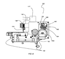
- FIG. 6 is side elevational view of the vacuum pick mechanism
- FIG. 7 is a cross-sectional side elevational view of the pick mechanism
- FIG. 8 is a cross-sectional view of a telescoping tube mechanism
- FIG. 9 is another cross-sectional side elevational view of the pick mechanism
- FIG. 10 is side view of the pick mechanism with the vacuum tubes extended
- FIG. 11 is a partial side view of the telescoping tube assembly
- FIG. 12 is a partial side sectional view of the telescoping tube assembly
- FIG. 13 is a side view of the telescoping assembly
- FIG. 14 is another side view of the vacuum pick mechanism
- FIG. 15 is yet another side view of the vacuum pick mechanism
- FIG. 16 is a perspective view of a product delivery assembly
- FIG. 17 is a bottom view of the product delivery assembly
- FIG. 18 is a cross-sectional plan view of the product delivery assembly
- FIG. 19 is a perspective view of a shelf assembly
- FIG. 20 is a partial perspective view of a shelf assembly
- FIG. 21 is a perspective view of a shelf assembly
- FIG. 22 is a perspective view of a shelf assembly
- FIG. 23 is a perspective view of a shelf assembly
- FIG. 24 is a perspective view of a shelf assembly
- FIG. 25 is a front perspective view of a refrigeration module
- FIG. 26 is a rear perspective view of the refrigeration module
- FIG. 27 is a side view of a refrigeration shelf assembly
- FIG. 28 is a partial side view of a refrigeration shelf assembly
- FIG. 29 is front isometric view of a bagging station and a lid placement station
- FIG. 30 is another isometric view of a bagging station and a lid placement station; and bagging station;
- FIG. 31 is a block diagram of on preferred vending machine
- FIG. 32 is an electrical schematic of the control board for one preferred vending machine
- FIG. 33 is a partial electrical schematic of a portion of a control board for one preferred vending machine
- FIG. 34 is yet another partial electrical schematic of a portion of a control board for one preferred vending machine
- FIG. 35 is a process flow diagram for a preferred vending machine
- FIG. 36 is a side view of a preferred embodiment of a pick mechanism
- FIG. 37 is another side view of the pick mechanism depicted in FIG. 36 ;
- FIG. 1 illustrates one preferred vending machine 10 that, in the embodiment, depicted, have a substantially rectangular shape.
- the machine 10 has a substantially arcuate shape that may be, e.g., substantially circular, substantially oval, and the like.
- machine 10 depicted in FIG. 1 is substantially rectangular, other rectilinear shapes may be used. Thus, e.g., machine 10 can be substantially square.
- the main body of machine 10 can be substantially rectilinear, and its end members may be arcuate.
- the vending machine 10 preferably contains a decorative header 12 .
- the header 12 which often is referred to as a “topper,” used to convey information.
- header 12 conveys information 14 on its front face 16 .
- different types of headers may be used, and they may convey different information.
- header 12 has a substantially rectangular shape with arcuate corners. Different shapes may be used for such header 12 . Thus, e.g. one may use a header whose top surface is not planar but, in at least a portion thereof, extends upwardly to define an upwardly-extending three-dimension object on such portion. In one aspect of this embodiment, the width of the header at one of its ends differs from the width of the header at the other of such ends.
- header 12 is comprised of an illuminator that provides illumination to the device 10 .
- the device 10 may comprise and illuminated sign comprised of one or more suitable illuminators.
- These illuminated sign devices are well known to those skilled in the art. Reference may be had, e.g., to U.S. Pat. No. 4,697,365 (edge illuminated sign, U.S. Pat. No. 4,929,936 (LED illuminated sign), U.S. Pat. No. 5,315,495 (illuminated sign device), U.S. Pat. No. 5,537,302 (illuminated sign with patterned openings on light dispersion member), U.S. Pat. No. 5,542,201 (indirectly illuminated sign), U.S. Pat. No. 6,607,412 (illuminated sign and method for design), U.S. Pat. No. 6,976,329 (illuminated sign unit), U.S. Pat. No. 7,360,910 (internally illuminated sign), and the like. The entire disclosure of each of these United States patents is hereby incorporated by reference into this specification.
- the illuminator comprises a multiplicity of lamps 16 and 18 that illuminate both the header 12 and the machine 10 . Although only two such lighting devices 16 / 18 are shown for the sake illustration, it will be apparent that more of fewer such lamps may be used.
- the illuminator may provide different forms of light.
- the illuminator may provide white fluorescent light.
- the light provide by the illuminator includes daylight which is more natural and pleasing.
- Lamps for providing daylight are well known to those skilled in the art. Reference may be had, e.g., to U.S. Pat. No. 3,757,101 (lamp for providing daylight effect), U.S. Pat. No. 4,458,176 (daylight fluorescent lamp), U.S. Pat. No. 5,418,419 (lamp for producing a daylight spectrum), U.S. Pat. No. 6,611,082 (lamp for producing daylight spectral distribution), and the like. The entire disclosure of each of these United States patents is hereby incorporated by reference into this specification.
- the illuminator in one embodiment, is comprised of one or more light emitting diodes (LEDs).
- LEDs light emitting diodes
- FIG. 1 light rays 20 extend substantially circumferentially around lamps 16 and 18 .
- the device 10 is comprised of one or more solar panels 15 .
- solar panels 15 These devices are well known and are described, e.g., in U.S. Pat. No. 4,205,662 (solar panel assembly), U.S. Pat. No. 5,542,203 (mobile sign with solar panel), U.S. Pat. No. 5,893,932 (portable cellular phone with integral solar panel), U.S. Pat. No. 6,948,826 (light box having a solar panel cover), U.S. Pat. No. 6,960,717 (adjustable solar panel), U.S. Pat. No. 7,224,286 (solar panel having visual indicator), and the like. The entire disclosure of each of these United States patents is hereby incorporated by reference into this specification.
- the lamps 16 and 18 are operatively connected to a controller 22 by means, e.g., of wire, not shown.
- the controller 22 is adapted to control the intensity and/or the direction of light rays 20 ; and it may provide direct lighting and/or diffuse lighting and/or variable color emissions.
- header 12 also is comprised of a multiplicity of speakers 24 and 26 that preferably are also operatively connected to the controller 22 .
- the speakers 24 and/or 26 , and/or the screen 28 , and/or communications module 30 are preferably used to convey instructions and/or cues and/or directions to a user.
- the entire disclosure of each of these United States patents is hereby incorporated by reference into this specification.
- device 10 is comprised of a screen 28 . It is preferred that screen 28 be part of a graphical user interface 29 .
- graphical user interface 29 are well known and are described and claimed in, e.g., U.S. Pat. No. 6,614,455 (directional navigation with a graphical user interface), U.S. Pat. No. 6,714,222 (graphical user interface for communications), U.S. Pat. No. 7,263,661 (multi-function device having graphical user interface incorporating customizable icons), and the like. The entire disclosure of each of these United States patents is hereby incorporated by reference into this specification.
- the graphical user interface 30 is preferably comprised of means for accepting payment 32 , such as a note reader and/or a coin acceptor/changer and/or a credit card reader and/or a closed user group card reader.
- means for accepting payment 32 such as a note reader and/or a coin acceptor/changer and/or a credit card reader and/or a closed user group card reader.
- a note reader and/or a coin acceptor/changer and/or a credit card reader and/or a closed user group card reader One may use any of the payment acceptance means known to those skilled in the art.
- U.S. Pat. No. 6,135,261 (payment-receiving enclosure for a vending machine), U.S. Pat. No. 6,505,095 (system for providing remote audit, cashless payment, and interactive transaction capabilities in a vending machine), U.S. Pat. No. 7,096,101 (cash payment system using vending machine), U.S. Pat. No. 7,108,180 (vending machine with
- An audit-credit-interactive system said system comprising: a micro controller; a vending machine interface interconnected with said micro controller, said audit-credit-interactive system, by way of said vending machine interface, interconnects to and data communicates with a vending machine controller, said vending machine controller is interconnected to and controls a vending machine; and an interactive interface interconnected with said micro controller, said interactive interface interconnects said audit-credit-interactive system to a computing platform, said computing platform, by way of said interactive interface and based in part on data communicated between said audit-credit-interactive system and said vending machine controller, monitors said vending machine activity, and selectively controls said vending machine vending cycles.”
- the payment accepting means 32 is preferably operatively connected to the controller 22 .
- the communications module 30 also is preferably connected to the controller 22 .
- the communications module 30 is comprised of an interactive display system such as, e.g., those disclosed in one or more of U.S. Pat. No. D425875 (interactive display system), U.S. Pat. No. 6,097,441 (system for dual-display interaction with integrated television and internet content), U.S. Pat. No. 7,113,921 (method and system for automatically displaying an image and a product in a page based on contextual interaction and metadata), U.S. Pat. No. 7,348,963 (interactive video display system), and the like.
- an interactive display system such as, e.g., those disclosed in one or more of U.S. Pat. No. D425875 (interactive display system), U.S. Pat. No. 6,097,441 (system for dual-display interaction with integrated television and internet content), U.S. Pat. No. 7,113,921 (method and system for automatically displaying an image and a product in a
- the communications module 30 in one embodiment thereof, is comprised of a shelf 34 on which is disposed sample product 36 that preferably is secured by a cable 38 to avoid misappropriation.
- the shelf 34 supports sample cards of perfume.
- the shelf 34 supports gaming controllers that allow a user to test video games being sold by the vending machine 10 .
- communications module 30 comprise an interactive display that allows the prospective customer to obtain more information about the product being vended and, in some cases, to sample and/or test such product.
- interactive displays are well known to those skilled in the art. Reference may be had, e.g., U.S. Pat. No. 4,814,755 (interactive display system), U.S. Pat. No. 4,268,826 (interactive display device), U.S. Pat. No. 5,274,363 (interactive display system), U.S. Pat. No. 5,324,416 (interactive display center), U.S. Pat. No. 5,680,159 (interactive display system using a laser disk player replaying video frames in response to touch force control monitor), U.S. Pat. No.
- the screen 28 and the payment accepting means 32 are part of a central control unit 40 that also comprises a means for delivering product 42 .
- the spatial relationship between central control unit 40 and cabinet 44 is more clearly illustrated in FIG. 2 , from which certain detail has been omitted for simplicity of representation.
- FIG. 3 is an exploded view of one preferred embodiment of cabinet 44 .
- cabinet 44 is comprised of lower shelve 46 and upper shelf 48 .
- Central control unit 40 is disposed between shelves 46 and 48 , and also between standards 50 and 52 and supports 54 and 56 .
- central control unit 40 is attached to standards 50 and 52 by means of slotted tabs (not shown) that engage rectangular openings 58 in the standards 50 and 52 .
- upper frame 60 is removably connected to standards 50 , 51 , 52 , and 53 as well as supports 54 , 56 , 57 , 58 , 59 , 61 , 62 , and 63 .
- lower frame 64 is also removably connected to standards 50 , 51 , 52 , and 53 as well as supports 54 , 56 , 57 , 58 , 59 , 61 , 62 , and 63 .
- the fact that such frames are removably connected facilitates the ability of the apparatus 10 to be readily disassembled, moved through a standard doorway, and reassembled.
- cabinet 44 is comprised of means for raising and/or lowering the shelves 46 and 48 and the apparatus 10 (not shown in FIG. 3 , but see FIGS. 1 and 2 ) disposed there between
- One may use conventional means known to those skilled in the art for effecting this movement.
- lower frame 64 is operatively connected to a pair of scissors jacks 66 and 68 that are adapted to move frame 64 in the direction of arrow 70 and/or 72 .
- These scissor jacks are well known and may be activated by either mechanical means, electrical means, or pneumatic means. Reference may be had, e.g., to U.S. Pat. No. 3,751,161 (scissor jack), U.S. Pat. No. 4,765,595 (scissors jack), U.S. Pat. No. 4,802,653 (scissors jack), U.S. Pat. No. 5,364,071 (scissors jack), U.S. Pat.
- cabinet is comprised of a top panel 74 and a front facing panel 76 .
- the cabinet 44 also is comprised of doors 78 and 80 which may be opened and closed. In the embodiment depicted in FIG. 2 , door 78 is open and door 80 is closed.
- each of doors 78 and 80 comprise a glass face 79 and 81 , respectively. It is also preferred that glass panes 83 and 85 be disposed on top of and beneath control unit 40 .
- one or both of the doors 78 and 80 are located on the rear facing side 89 of the machine.
- the 86 , 87 and 88 are preferably arranged in such a way as to allow the products 90 and 91 to be viewed from the customer (not shown) in a clear and easily recognizable manner.
- the customer can view the product labeling 92 and 93 in a normal reading orientation.
- the products 90 and 91 can be loaded into the trays 86 , 87 and 88 directly from the front of the vending machine 10 when the doors 78 and 80 are opened.
- roller chain 98 is part of a 3-axis drive mechanism 100 (see FIG. 4 ) that is illustrated in more detail in FIG. 4 et seq.
- the 3-axis drive mechanism is preferably adapted to move a drive in the X, Y, and Z axes.
- These mechanisms are well known to those skilled in the art. Reference may be had, e.g., to U.S. Pat. No. 4,256,218 (three axis transfer apparatus), U.S. Pat. No. 4,401,406 (remote three axis cable transport system), U.S. Pat. No. 5,324,163 (three-axis Cartesian robot), U.S. Pat. No.
- FIG. 4 illustrates a 3-axis drive mechanism 100 , which comprises a vacuum pick mechanism 102 and a support rail apparatus 104 .
- roller chain 82 and 122 are connected to the end caps 121 and 123 and to a reversible motor 118 which cause the support rail to move vertically in the Y axis as indicated by arrows 106 and 108 .
- the support rail apparatus 104 is movably disposed on vertical rails 96 and 97 (see FIG. 4 ) and is adapted to be moved thereon by chains 82 and 122 .
- the roller chains 82 / 122 are preferred flexible drive means that, in combination with reversible motor 118 and controller 22 (not shown in FIG. 4 , but see FIG. 1 ) to which the motor 118 is operatively connected, comprise a motion control device.
- a motion control device Any of the motion control devices known to those skilled in the art such as, e.g., the devices disclosed in U.S. Pat. No. 4,847,543 (motion control drive interface), U.S. Pat. No. 4,855,661 (motion control apparatus for induction motor), U.S. Pat. No. 5,267,604 (motion control system for horizontal continuous caster), U.S. Pat. No. 6,297,6212 (motion control coupling apparatus), U.S. Pat. No.
- the pick mechanism 102 is preferably connected to reversible drive motor 154 and drive belt 150 which allows the pick mechanism 102 to move horizontally in the X axis as indicate by arrows 110 and 112 .
- the pick mechanism is capable of moving in the Z-axis as indicated by arrows 114 and 116 and is further described below.
- a vacuum pick mechanism such as a picker
- the vacuum pick mechanism disclosed in U.S. Pat. No. 5,240,139 the entire disclosure of which is hereby incorporated by reference into this specification.
- x-y beam 18 is suspended above sliding panels 14 and outside freezer compartment 12 between y rails 20 which are attached opposite one another near the top of cabinet sides 22.
- Beam 18 has ball-bearing rollers 22 which rest on y rails 20 at either end thereof.
- the side to side movement of x-y carriage 28 is accomplished by X motor 30 which is suspended in a stationary position on the underside of x-y beam 18.
- X-y carriage 28 and X motor 30 may be connected in a variety of ways such as by an endless chain which engages toothed sprockets (not shown) provided on both x-y carriage 28 and X motor 30. Movement of x-y beam 18 is similarly accomplished by providing Y motor 32 for driving Y axle 34. Y axle 34 has one gear 35 at each end thereof, enmeshed with toothed rack 37. The positions of x-y carriage 28 and x-y beam 18 are determined by X position sensor 36 and Y position sensor 38, respectively, which feed distance measurements to an automatic control system 40 located adjacent to freezer compartment 12 which governs and coordinates all the operations of the present invention. The preceding arrangement for positioning the x-y carriage 28 over the correct dispensable product may be referred to collectively as the x-y positioning means.”
- U.S. Pat. No. 5,240,139 also discloses that “A blower motor 42 is housed between machine cabinet 10 and freezer compartment 12. Blower motor 42 has connected thereto a flexible air hose 44, which air hose 44 is connected at its other end to x-y carriage 28 which comprises an air conduit 46.
- X-y carriage 28 has a picker guide tube 48 extending down therefrom which houses a longitudinally-compressible hose 50.
- Picker guide tube 48 has mounted on an outer surface thereof a z-origin sensor 51 for a purpose which will be more fully discussed hereinbelow.”
- Claim 2 of U.S. Pat. No. 5,240,139 discloses: “2.
- Claim 3 of PCT/GB1004/002501 describes: “8. Apparatus according to any preceding claim, comprising an optical detector on the carriage for identifying the article in a storage location.”
- Claim 11 of PCT/GB1004/002501 describes: “11. Apparatus according to any preceding claim, wherein the array of storage locations comprises a delivery location from which an article may be manually retrieved.”
- Claim 12 of PCT/GB1004/002501 describes: “12. A vending machine comprising apparatus according to Claim 9, located within a closed cabinet providing access only to said delivery location, selection means on the cabinet for sending an article selection signal to control means to indicate the choice of article to be vended by the machine, and payment means for receiving a payment in relation to the article and for sending a payment signal to the control means when the payment has been received, wherein the control means is arranged to control the movement of the carriage and the operation of the arm in response to receipt of the article selection and payment signals to deliver the selected article from the respective storage location to said delivery location.”
- Claim 13 of PCT/GB1004/002501 describes: “13. A vending machine according to Claim 12, wherein the cabinet is provided with a transparent panel in one vertical face thereof, and the array of storage locations is positioned with the vertical face thereof opposite to that over which the carriage is movable adjacent to the transparent panel, whereby the contents of all the storage locations are visible from outside the cabinet.”
- Claim 14 of PCT/GB1004/002501 describes: “14. A vending machine according to Claim 13, comprising a door in the cabinet for the delivery location.”
- pick mechanism 102 is comprised of a comprises of a vacuum chamber 130 , which is rigidly mounted to the carriage 132 .
- the vacuum chamber 130 delivers negative air pressure from a vacuum source 131 to elastic suction cup 156 .
- other vacuum sources such as, e.g., those disclosed in U.S. Pat. No. 6,148,902 (multiple die casting machines with single vacuum source), U.S. Pat. No. 6,315,524 (pump system with vacuum source), U.S. Pat. No. 6,585,492 (pump system with vacuum source), U.S. Pat. No. 6,830,416 (system and method for securing workpieces to a worktable of a CNC machining system utilizing a low level vacuum source), and the like.
- the entire disclosure of each of these United States patents is hereby incorporated by reference into this specification.
- a preferred suction control device (a vacuum pressure switch) is disclosed.
- the vacuum pressure switch 142 is connected to the vacuum chamber 130 .
- a snap action or contact switch 144 is connected to the carriage 132 and has a lever 146 that remains in contact with the suction tube 140 when the tube is in the fully retracted position.
- a support plate 148 is rigidly attached to the end of suction tube 140 providing support when the tube is fully extended as described below. Without wishing to be bound to any particular disclosure, applicant believes that the tube without the support plate 148 could sag over the length of its extension causing a pick failure.
- the carriage 132 is operatively connected to a drive belt 150 . Rollers 152 ride on the support rail 104 .
- the drive belt 150 is attached to a drive reversible drive motor 154
- the telescoping tubes 135 , 136 , 137 , 138 , 139 , and 140 are preferably connected to a friction drive to cause them to extend or retract.
- a friction drive to cause them to extend or retract.
- a motor-driven, telescoping antenna for automobiles comprising an electric motor having a rotatable armature; an extensible antenna rod passing through the center of the armature and slidable freely with respect thereto, a helically coiled spring (a) fixed to the bottom end of said antenna rod; a rotatable drive tube (d) attached to the bottom end of said armature and rotatable therewith; an angularly bent pin (b) fixed to the bottom end of said drive tube and having one horizontal arm extending between coils of said spring, and a vertical arm extending longitudinally through the center of the spring; said spring having bridges (h) extending between adjacent coils at each end thereof, said bridges being engaged by said pin (b) at the end of the linear travel of said spring during extension or retraction of the antenna, thereby
- a motor 158 is affixed to the carriage 132 and connected to a friction drive roller 160 by means of gears 162 , 163 , 164 , 165 and 166 , drive shaft 168 .
- a flat spring coil 170 is compressed between the friction drive roller 160 and an idler roller 172 .
- the end of the flat spring coil 170 is rigidly connected to the end of tube 140 .
- Also connected to the tube 140 is an elastic suction cup 156 .
- the gears 162 , 163 , 164 and 165 cause the friction drive roller 160 to rotate imparting a friction drive force to the flat coil spring 170 and imparting a force on the end of the tube 140 causing it to move in a linear direction and telescope outwards increasing the length of the telescoping pick mechanism 102 .
- the suction cup 156 is preferably a bellows suction cup.
- a bellows suction cup is disclosed, e.g., in U.S. Pat. No. 4,582,353 and in claim 1 thereof, which discloses: “1.
- a carton feeder located adjacent said magazine and transport conveyor for engaging flat folded cartons in said magazine, erecting said cartons and placing said cartons between said transport lugs, said carton feeder comprising: a channel-shaped element, having parallel legs, said legs being spaced apart approximately a distance L, at least one bellows suction cup mounted on said channel-shaped element and located between said legs, means connected to said suction cup for applying a vacuum to said suction cup, and means connected to said channel-shaped element for moving said channel-shaped element and suction cup between said magazine and said transport conveyor, said suction cup engaging a top wall of said carton and drawing said top wall and a portion of the side walls between the legs of said channel-shaped member to substantially erect the carton and deposit it between leading and trailing lugs of said transport conveyor;” and such suction cup is
- Bellows suction cups are well known to those skilled in the art and are commercially available, e.g., from the Anver Corp. of 36 Parmenter Road, Hudson, Ma. 01749. One may use, e.g., bellows suction cups that have from about 1.5 to about 2.5 bellows and a diameter of from about of from about 0.7 to about 2.0 inches; suitable bellows suction cups available from Anver Corp. include model B1.5-25-SIT, B1.5-20-SIT, B-1.5-42-SIT.
- the bellows suction cup is preferably made from translucent material. It is preferred that the bellow suction cup comprise or consist essentially of silicone rubber. As is known to those skilled in the art, silicone rubber is usually a long-chain dimethyl silicone which will flow under heat and pressure but can be vulcanized by cross-linking the linear chains. Reference may be had.
- the bellows suction cup has a Durometer hardness (Shore A) of less than about 45.
- the telescoping tubes such as tube 135 , be comprised of a metal alloy material 211 with a coating 213 disposed on top of such material.
- the metal alloy material is preferably a half hard brass that has a thickness of from about 0.01′′ to about 0.04.′′ In one aspect of this embodiment, several of the tubes have a thickness of about 0.014′′, and several of the tubes have a thickness of 0.029′′.
- the coating disposed on top of the half-hard brass have a thickness of from about 0.00005 to about 0.001 inches.
- the coating is a wear-resistant material such as a chromium plating.
- chromium plating is widely used where extreme hardness or resistance to corrosion is required, and it utilizes plates up to about 0.05 inches.
- the telescoping tubes are comprised of means for preventing the interior section of the tube from becoming disengaged from the exterior section of the tube.
- tube 135 is disposed within tube 134 ; tube 136 is disposed within tube 135 ; tube 137 is disposed within tube 136 ; tube 138 is disposed within tube 137 ; tube 139 is disposed within tube 138 ; and tube 140 is disposed within tube 139 .
- the overall assembly depicted in FIG. 1 is telescoping tube 205 .
- Each of the tubes 134 et seq. has a length that preferably is less than about 4.5 inches.
- the overall length of the telescoping tube assembly 205 (see FIG. 10 ), when collapsed, is preferably less than about 5 inches; the extended length is at least about 22 inches; and the ratio of the extended length to the collapsed length is at least about 4.0.
- a pick mechanism is illustrated, e.g., in FIGS. 4 and 5 of International publication WO 2004/114233.
- the suction tube 15 is attached to a series of telescoping tubes 16a-16e.
- Tube 16a is rigidly affixed to the table 11 and connected to the vacuum suction tube 15.”
- the tubes 134 , 135 , 136 , 137 , 138 , 139 , 140 have external stepped rings 174 , 175 , 176 , 177 , 178 and 179 rigidly attached to them.
- the tubes also have an external stepped ring 180 , 181 , 182 , 183 and 184 .
- the rings external step rings 174 , 175 , 176 177 , 178 and 179 will eventually contact the internal stop tings 180 , 181 , 182 , 183 and 184 causing the tubes to extend outwards.
- the stop rings 186 , 187 , 188 , 189 and 190 impart a force to the adjacent tube causing that tube to be pulled back.
- the stop rings 186 , 187 , 188 , 189 and 190 also prevent the tubes from over travel in the reverse mode and prevent concentric disengagement of the tubes.
- the tubes 134 , 135 , 135 , 136 , 137 , 138 , 139 and 140 are contracted in such a way as to provide an air path for providing negative pressure (vacuum) at the elastic suction cup 156 .
- the telescoping tubes 134 , 135 , 135 , 136 , 137 , 138 , 139 and 140 are shown in a fully extended position. It should be noted that the telescoping tubes 134 , 135 , 135 , 136 , 137 , 138 , 139 and 140 can be extended to any distance between the fully retracted position and the fully extended position, thereby allowing for the retrieval of a product or multiple products in any of the storage locations in the array.
- the support plate 148 is shown making contact with a product tray 86 , 87 and 88 effectively keeping the extended height of the suction cup 156 at the same height as if in the fully retracted position.
- the articles 90 , 92 and 93 are positioned directly behind the glass face 79 and 81 at the front of the machine, and the pick mechanism 102 is positioned at the rear of the machine to pull the articles off the trays 86 , 87 and 88 from the rear of the line of articles on the tray, so that the front article remains visible through the window to assist the customer in selecting the desired article.
- the articles picked from the tray are then delivered to the product delivery 42 , as hereinafter described, for retrieval at the front of the machine.
- one possible vacuum source comprises of a vacuum fan motor 212 and a vacuum fan 214 contained in a casing 216 , which is rigidly mounted on the pick mechanism 102 .
- a suction tube 218 extends between the casing 216 and the vacuum chamber 130 in turn connected to the telescoping tubes 134 - 140 .
- the vacuum source may reside separately form the pick mechanism 102 and be connected to the pick mechanism by a standard vacuum hose.
- FIGS. 14 and 15 illustrate an apparatus and a process for moving the suction cup 156 relative to the carrier tray 206 , to allow for optimum product attachment on the vertical axis.
- a reversible motor 286 is rigidly connected to casing 216 and attached to arm 287 .
- a series of slots 290 are in the casing 216 and receive pins 292 on the vacuum chamber 130 .
- the controller 22 turns the motor 286 causing the arm 297 to contact the bottom of the vacuum chamber 130 and allowing it to raise or lower depending on the need.
- the relative distance as indicated by arrows 294 and 296 .
- the lock controllable product delivery door 42 comprises a frame 248 , a rotating drum 250 , axially mounted bushings 252 pivotally mounted to the frame 248 for means of rotating the drum 250 , a worm gear 254 driven by a motor 256 , two optical sensors 258 and 260 , and guide walls 262 and 264 .
- the drum 250 is operatively connected to the controller 22 . It may be caused to rotate by conventional means.
- a worm gear 254 is engaged with a worm wheel 266 , which is rigidly connected to a spur gear 268 , the spur gear being engaged with a driven gear 270 .
- the driven gear 270 is rigidly mounted to the drum 250 .
- An actuator is rigidly mounted to the driven gear 270 and makes contact with one of two switches 274 and 276 when the drum is fully opened or fully closed.
- the worm gear 254 provides the locking force required to keep the drum 250 locked in the closed or open position.
- the vacuum tubes 234 - 240 extend to push the article 90 into the rotating drum 250 in the direction of arrow. If one of the optical sensors 258 or 260 is blocked by article 90 , a signal is sent to the controller causing the motor 254 to rotate in the direction of arrow 280 and open the drum 250 . When the drum 250 rotates, the article can be retrieved from the drum through an opening 282 . When the article 90 is removed, the sensor 258 or 260 is unblocked and the controller causes the motor 254 to reverse, closing the drum 250 to a full locked position.
- a sensor array 285 is mounted to the frame 248 so as to allow scanning of the product 90 when positioned in the drum 250 .
- the sensor array may use optical scanning technology such as bar code scanning or may us radio frequency-scanning method know as RFID.
- optical scanning technology such as bar code scanning or may us radio frequency-scanning method know as RFID.
- the assembly described can determine whether, in fact, the article has actually been delivered to a customer. If it is determined that a delivery has not occurred, the machine controller 22 will not charge the customer and can enter into a “recovery mode” or an “out of service condition.” This feature is described in more detail in the process section of the case.
- FIG. 18 illustrates that, when product is being delivered, the machine logic causes aperture 282 to close so that, if one sticks his or her hand in the direction of arrow 278 , the hand will be blocked by wall 259 .
- Yet another advantage is that the worm drive gear 254 , when it is not moving, effectively locks the drum 250 so that, if one manually attempts to move the drum, he or she will be foiled.
- the device 10 may be used with conventional display and storage systems.
- the entire disclosure of each of these United States patents is hereby incorporated by reference into this specification.
- FIG. 19 is a schematic view illustrating one preferred display and storage system 300 that that may be used in conjunction with device 10 .
- Such display and storage system 300 is comprised of a display glass 81 and a support shelf 86 ; the support shelf may be similar to those used in used in cooler, freezer or vending machine as normally used in a point of sale location.
- a multiplicity of sidewalls 302 define a channel 303 in which objects can be placed.
- a bristle brush 304 is preferably rigidly attached to the sidewalls 302 .
- Sample products 306 and 308 are placed between opposing sidewalls 302 and opposing bristle brushes 304 .
- FIG. 20 is close up view of the apparatus 300 .
- the opposing bristle brushes 304 make contact with products 306 and 308 and allow them to stand upright in the shelf.
- applicant believes that such bristle brushes are especially adapted to maintain product 306 and 308 in a standing position but to readily facilitate their removal form the support shelf 86 .
- bristle brushes are well known. Reference may be had, e.g., to U.S. Pat. No. 3,384,915 (multiple compliant bristle brush), U.S. Pat. No. 3,500,491 (bristle brush), U.S. Pat. No. 5,327,608 (moving bristle brush), U.S. Pat. No. 6,968,848 (retractable bristle brush), and the like. The entire disclosure of each of these United States patents is hereby incorporated by reference into this specification.
- the bristles brushes 302 are preferably made of a flexible material allowing them to conform to the shape of the objects 306 and 308 .
- the bristles brush 304 are of sufficient strength to hold the objects 306 and 3087 in an upright position, allowing the point of sale customer to see them in a normal viewing orientation.
- the rear object 307 in the channels can be retrieved by means of any robotic method.
- the remaining products 306 and 308 in the channels will remain in their position.
- FIG. 21 shows the sidewalls 302 disengaged from the shelf 86 .
- a series of slots 310 in the shelves and a series of tabs 312 on the sidewalls align in such a way as to allow the sidewalls to be moved to various slots 310 on the support shelf 86 allowing the bristle brushes 304 to be adjusted for best resistance on the product 306 and 308 and allowing a variety of product widths to be used.
- the sidewalls 302 can be used without the Bristol brushes 304 for any product not requiring side resistance to stand upright.
- a shelf 314 is comprised of a frame 316 and a glass plate 318 .
- the frame 314 has a series of slots 320 orientated to accept the sidewall 322 .
- the frame 316 can accept any number of sidewalls 322 .
- the glass plate 318 allows light to pass through the shelves 314 or a series of shelf's enabling the products 36 to be highly visible.
- FIG. 23 illustrates a shelving assembly 317 that is comprised of a light source 324 that is rigidly attached to the bottom of the shelf 314 .
- the light source 324 can illuminate through the glass plate 318 .
- the light source can provide, e.g., fluorescent, incandescent, or LED lighting; in one embodiment, it provides daylight.
- the light source 324 can be used with shelf 86 as described elsewhere in this specification to cause products below it to be illuminated.
- FIG. 24 show a shelving assembly 319 that is comprised of a shelf 86 with an array of hooks 326 attached below it.
- the hooks 326 can be used hang an array of products 328 to it.
- a refrigeration module 350 is disclosed that may be disposed in device 10 behind either door 78 and/or door 80 .
- the refrigeration unit 350 may be disposed on top of lower frame 64 , beneath upper frame 60 , between supports 54 and 58 , and between standards 50 and 53 .
- the refrigeration module 350 is comprised of a multiplicity of insulated panels that preferably include side panels 352 and 354 , a top panel 356 , and a bottom panel 357 ; the module also includes a series of shelves 358 .
- the refrigeration module preferably includes a refrigeration deck 368 .
- These refrigeration decks are well known. Reference may be had, e.g., to U.S. Pat. No. 4,781,310 (beverage dispenser), U.S. Pat. No. 4,801,048 (beverage dispenser), U.S. Pat. No. 5,335,988 (foil access cover for refrigeration deck), U.S. Pat. No. 6,581,389 (merchandiser using slide-out stirling refrigeration deck), and the like. The entire disclosure of each of these United States patents is hereby incorporated by reference into this specification.
- the shelves 358 are preferably comprised of a horizontal frame 360 that has a reversible motor 362 rigidly attached to it.
- the motor 364 is connected through a link 364 to a hinged panel 366 .
- the hinged panel 366 is connected to the frame 360 .
- the controller 22 causes the motor 362 to rotate and open the panel 366 exposing the product to the ambient environment and allowing the pick mechanism 102 to actively capture the product and deliver to the end user.
- Refrigerated air can be delivered through any of the four side panels 352 , 353 , 354 , 355 , top panel 356 or bottom panel 357 .
- an automatic bagging station and a beverage lid placement station 400 is comprised of hot/cold beverage fill mechanism 402 , a cup lid mechanism 404 and a bagging station 406 .
- the automatic bagging station and a beverage lid placement station 400 can be easily adapted to fit into the same style of cabinet 44 as described above.
- a bagging station 406 is comprised of a bag storage bin 408 , a vacuum bag pick manifold 410 , and a vacuum bag-expanding manifold 412 .
- the bag storage bin 408 comprises an elevator 414 that holds empty folded bags in storage.
- the bag pick manifold 410 is mounted on a linear transport 414 and fixed in such a way as to rotate form vertical to horizontal.
- the bag picks mechanism 410 and is operatively connected to a vacuum source.
- the bag pick manifold 410 rotates horizontally and makes contact with the upper most bags 407 in the bag storage bin and effectively seals the bag to the manifold 410 by vacuum pressure.
- the manifold 410 then rotates vertically and moves linear until the bag 407 makes contact with the bag expanding mechanism 412 , which uses the same vacuum sources as the bag pick manifold 410 .
- the bag pick manifold 410 then reveres causing the bag 407 to expand to an open position.
- the door 416 then opens to allow the customer to obtain their products. Multiple items can be place in the expanded bag prior to delivery.
- a cup carousel 418 common to those skilled in that art drops a cup 420 onto a rotating cup transport 422 .
- the rotating cup transport 422 then rotates the cup 420 to a fill station 424 where either a cold or hot beverage is dispensed into the cup 420 .
- the cup 420 then further rotates on the cup transport 422 and stops at a lid placement station 426 .
- a cup lid mechanism 428 then picks a lid 430 from the lid storage carousel 432 and places the lid 30 onto the cup 420 .
- a cup gantry mechanism 434 then lifts the cup, with the lid 430 in place the cup gantry 434 lifts transports the cup it to the bag station 406 .
- the cup gantry 34 then lowers the cup 420 into the expanded bag 407 .
- a door 416 then opens and allows the customer to take the filled beverage cup 420 .
- the door 436 closes and waits for the next cycle to begin.
- an automatic bagging station and a beverage lid placement station 400 is comprised of hot/cold beverage fill mechanism 402 , a cup lid mechanism 404 and a bagging station 406 .
- the automatic bagging station and a beverage lid placement station 400 can be easily adapted to fit into the same style of cabinet 44 as described above.
- a bagging station 406 is comprised of a bag storage bin 408 , a vacuum bag pick manifold 410 , and a vacuum bag-expanding manifold 412 .
- the bag storage bin 408 comprises an elevator 414 that holds empty folded bags in storage.
- the bag pick manifold 410 is mounted on a linear transport 414 and fixed in such a way as to rotate form vertical to horizontal.
- the bag picks mechanism 410 and is operatively connected to a vacuum source.
- the bag pick manifold 410 rotates horizontally and makes contact with the upper most bags 407 in the bag storage bin and effectively seals the bag to the manifold 410 by vacuum pressure.
- the manifold 410 then rotates vertically and moves linear until the bag 407 makes contact with the bag expanding mechanism 412 , which uses the same vacuum sources as the bag pick manifold 410 .
- the bag pick manifold 410 then reveres causing the bag 407 to expand to an open position.
- the bag 407 When the bag 407 is in the open position it can receive product from a chute or other means as described below.
- the door 416 then opens to allow the customer to obtain their products. Multiple items can be place in the expanded bag prior to delivery. Alternatively, multiple bags may be delivered as a result of only one payment, each of which may contain one or more items.
- FIG. 31 is a block diagram of one preferred vending machine system 10 .
- vending machine refers to any apparatus that stores and dispenses one or more articles.
- one or more of the devices depicted in FIG. 31 and/or the processes depicted in FIG. 31 and/or the software used in conjunction with FIG. 31 may be used to modify the devices and processes depicted in such prior art vending machines as those described in U.S. Pat. No. 3,653,480 (automatic vending system), U.S. Pat. No. 3,935,933 (automatic article vending machine), U.S. Pat. No. 4,051,978 (merchandising compartmenting arrangement for an automatic vending machine), U.S. Pat. No.
- vending machine system 10 is comprised of one or more vending machine controllers (such as, e.g., 22 and the graphical interface 29 . Furthermore, it is preferred to additional control devices such as, e.g., P/C 244 ; these additional devices will be described elsewhere in the specification.
- vending machine controllers such as, e.g., 22 and the graphical interface 29 .
- additional control devices such as, e.g., P/C 244 ; these additional devices will be described elsewhere in the specification.
- the vending machine controller 22 may be any of the vending machine controllers conventionally used for vending machines. Thus, by way of illustration and not limitation, one may use the controllers described in U.S. Pat. No. 5,154,272 (controller for an automatic vending machine), U.S. Pat. No. 5,197,588 (controller for vending machine), U.S. Pat. No. 5,595,869 (vending machine controller and system), U.S. Pat. No. 6,839,775 (method and apparatus for vending machine controller configured to monitor and analyze power profiles for plurality of motor coils to determine condition of vending machine), and the like. The entire disclosure of each of these United States patents is hereby incorporated by reference into this specification.
- a vending-machine controller comprising: a programmable processor controlling operation of the vending machine; a first serial port connected to the programmable processor; an arbitrator operable in a hunt mode to monitor an input from each of at least two serially-communicating devices, respectively, to determine that a communication session is being initiated by one of the serially-communicating devices if activity is present upon an input, and to connect the first serial port of the programmable processor to the serially-communicating device that first initiates a communication session; and a second serial port configured as one of a multi-drop bus interface and a VCCS bus interface for connecting the programmable processor to a multi-drop bus or a VCCS bus, respectively.”
- controller 22 is an embedded controller.
- embedded controllers are well known and are described, e.g., in U.S. Pat. No. 6,948,098 (circuits and methods for debugging an embedded processor and systems using the same), U.S. Pat. No. 6,976,136 (flash memory protection scheme for secured shared BIOS implementation in personal computers with an embedded controller), U.S. Pat. No. 6,859,886 (IO based embedded processor clock speed control), U.S. Pat. No. 6,985,441 (intelligent embedded processor enabled mechanism to implement RSVP function), U.S. Pat. No. 7,139,077 (using an embedded processor to implement a finite state machine), U.S. Pat. No.
- an embedded controller is a device that performs embedded control.
- the I/O system is not connected to an external PC but, instead, the processor running the system is actually incorporated into the I/O chassis itself.
- FIGS. 32, 33, and 34 A schematic of a preferred control board is illustrated in FIGS. 32, 33, and 34 which describe, respectively, a preferred microcontroller 22 ( FIG. 32 ) an onboard power supply unit 600 , a serial I/O unit 602 , LED outputs 604 , an MDB (multidrop bus) interface) 606 , an I2C bus 608 , spare I/O's 610 , 612 , and 614 , ( FIG. 33 ), and three-axis drive mechanism outputs 616 , 618 , and 620 , ( FIG. 34 ).
- a preferred microcontroller 22 FIG. 32
- an onboard power supply unit 600 a serial I/O unit 602 , LED outputs 604 , an MDB (multidrop bus) interface) 606 , an I2C bus 608 , spare I/O's 610 , 612 , and 614 , ( FIG. 33 ), and three-axis drive mechanism outputs 616 , 618 ,
- embedded processor 22 is comprised of a multiplicity of inputs—outputs (I/O's) that allow processor 22 to communicate with other circuits and/or other components of the circuit. It is preferred that the embedded processor contains at least 40 such I/O's and, preferably, at least 50 such I/O's. In one embodiment, the processor 22 contains 60 such I/0's.
- Controllers comprised of a multiplicity of I/O's are well known to those skilled in the art. Reference may be had, e.g., to U.S. Pat. No. 3,654,617 (microprogrammable I/O controller), U.S. Pat. No. 4,293,924 (programmable controller with high density intelligent I/O interface), U.S. Pat. No. 4,504,927 (programmable controller with expandable I/O interface circuitry), U.S. Pat. No. 4,510,565 (programmable controller with intelligent positioning I/O modules), U.S. Pat. No. 5,778,236 (multiprocessing interrupt controller on I/O bus), U.S. Pat. No.
- the embedded controller 22 is operatively connected to X-drive assembly 616 , Y-drive assembly 618 , Z-drive assembly 620 .
- embedded controller 22 is preferably connected to a delivery door assembly 624 (see FIG. 32B ), a liquid crystal display 626 (LCD) assembly (see FIG. 32C ), an alpha-numeric keypad assembly 628 (see FIG. 32D ), a vacuum release mechanism 630 (see FIG. 32E ), a temperature sensor assembly 632 (see FIG. 32F ), a clock 634 (see FIG. 32G ), non-volatile RAM 636 (see FIG. 32G ), a Y switch assembly 622 (see FIG. 32H ) and an in circuit programming port 668 .
- a delivery door assembly 624 see FIG. 32B
- LCD liquid crystal display 626
- an alpha-numeric keypad assembly 628 see FIG. 32D
- a vacuum release mechanism 630 see FIG. 32E
- a temperature sensor assembly 632 see FIG. 32F
- a clock 634 see FIG. 32G
- non-volatile RAM 636 see FIG. 32G
- Y switch assembly 622 see FIG
- the apparatus is comprised of a controller assembly 22 that is preferably comprised of the circuitry illustrated, e.g., in FIGS. 32,33 and 34 .
- the controller assembly 22 is connected to the a power supply unit 638 that, in the embodiment depicted, is connected via line 640 to the main power supply,
- the power supply 638 preferably delivers alternating current to onboard power supply 600 .
- the onboard power supply 600 converts the alternating current fed to it (which is often 23 volts A.C.) to a multiplicity of direct current outputs.
- the power supply 638 also delivers alternating current via line 642 to vacuum source 131 (see FIG. 5 ).
- Vacuum source 131 is connected to vacuum release circuitry 630 that is illustrated, e.g., in FIG. 32E .
- the power supply 638 is also operatively connected to a refrigeration module 350 comprised of a refrigeration deck 368 (see FIG. 25 ).
- the power supply 638 is connected via line 644 to a lower voltage power supply 646 that converts that 23 volt alternating current into direct current such as, e.g., 12 volt d.c.
- This direct current is fed to telemetry unit 648 , printer 235 , credit card reader 232 , touch screen 28 , coin acceptor assembly 230 , note reader 228 , automatic teller machine 238 , and note changer 236 .
- each of these components is operatively connected to, and controlled by, computer 244 which also is directly connected to power supply 638 by line 650 .
- the computer 244 is linked to the controller 22 .
- the computer is so linked by line 652 .
- the computer is linked by a wireless link.
- the computer is preferably linked to a serial port 602 (see FIG. 33 )
- I2C also known as Inter-Integrated Circuit
- I2C is a multi-master serial computer bus that is used to attach lower-speed peripherals to a motherboard, embedded system, or cellphone.
- the I2C bus 608 is adapted to turn the alternating current power on and off to the refrigeration assembly 350 and the vacuum source 131 .
- the controller 22 monitors certain conditions that dictate when such power is turned on and off. This monitoring may be effected by conventional means such as, e.g., by temperature sensor 658 (see FIG. 32F ).
- temperature sensor 658 is operatively connected to control board 660 by means not shown in FIG. 32F , but see FIG. 35 .
- temperature sensor circuit 660 is connected to temperature sensor 658 by means of line 662 .
- Vacuum sensor 144 is connected to vacuum switch 621 (see FIG. 34C ) that, in turn, is connected to Z axis interconnect board 664 ; interconnect board 664 is connected to control panel 22 a.
- an ultrasonic sensor 157 (see FIG. 5 ) is also connected to Z-axis interconnect board 664 .
- the graphical interface is comprised of any number of the following components: note reader 228 , coin acceptor 230 , credit card reader 232 , closed user group card reader 234 , a note changer 236 , a automatic teller machine (ATM) 238 or any other form of payment and also can be set to a no-payment option.
- the communication system 220 can communicate with a selection keypad 240 and a selection information display screen 242 or can be linked directly by serial bus to a p/c 244 .
- the personnel computer 244 can be used to manage all the transaction functions including incorporating a touch screen 28 for user the interface and can also receive and send information via wired telecom, wireless telecom, wifi, internet, or intranet communications.
- the information can include, machine conditions, number of vends, amount of stock, all accounting information.
- the personnel computer 244 can also receive and implement software via the same.
- the motion control system controls the movement of the 3-axis drive mechanism 100 , the vacuum pick mechanism 102 , the product delivery 42 and the refrigeration control 246 when required.
- the note reader 228 , credit card reader 232 , closed user group card reader 234 and coin acceptor/changer 230 may be controlled either by the controller 22 or the personnel computer 244 .
- the controller 22 is capable of storing the product data pertaining to the amount of product in the machine, the cost of each product and the amount of product sold. This information can be stored locally in memory or transmitted by any on the above-described means to a remote location for inventory control purpose. It is also a preferred embodiment that the machine conditions be stored in memory and the data can also be transmitted by any of the above means to a remote location for the purpose of dispatching a technician or alternately solving any issues with a supervisor at the machine.
- FIG. 35 is a flow diagram of one preferred process 500 for vending articles.
- an article to be vended is selecting.
- Devices and processes for selecting articles are well known and are described, e.g., in U.S. Pat. No. 3,731,788 (article selecting device), U.S. Pat. No. 3,826,348 (article selection and separation apparatus), U.S. Pat. No. 4,436,474 (selecting articles from an array thereof), U.S. Pat. No. 5,564,894 (article selection and delivery method and apparatus), U.S. Pat. No. 6,415,952 (apparatus for carrying selected article to take-out window in automatic vending machine), and the like. The entire disclosure of each of these United States patents is hereby incorporated by reference into this specification.
- the selection process might be facilitated by the graphical interface 29 (see FIG. 1 ), and by the screen (which preferably is a touch screen) 28 .
- touch screens are well known and are described, e.g., in U.S. Pat. No. 5,564,974 (coin sorting system with touch screen device), U.S. Pat. No. 5,768,386 (method and system for encrypting input from a touch screen), U.S. Pat. No. 6,688,518 (wall mounted touch screen information system), U.S. Pat. No. 6,741,237 (touch screen), U.S. Pat. No. 7,079,118 (touch screen using echo location), and the like. The entire disclosure of each of these United States patents is hereby incorporated by reference into this specification.
- step 501 the consumer makes payment by inserted payment into the machine in step 501 .
- payment making processes are well known to those skilled in the art are described, e.g., in U.S. Pat. No. 4,797,540 (payment making terminal device), U.S. Pat. No. 5,154,260 (method and system for automated processing of articles), U.S. Pat. No. 5,239,480 (automatic ticket dispensing system), U.S. Pat. No. 5,860,362 (newspaper vending machine with online connection), U.S. Pat. No. 6,796,491 (electronic payment system, payment apparatus, and terminal thereof), U.S. Pat. No.
- MDB multi-drop bus
- the MDB is often used with vending machines. Reference may be had, e.g., to the disclosure and claims of U.S. Pat. No. 5,959,869 (vending machine controller and system), U.S. Pat. No. 6,119,053 (vending machine dual bus architecture), U.S. Pat. No. 6,505,095 (system for providing remote audit, cashless payment, and interactive transaction capabilities in a vending machine), U.S. Pat. No. 6,628,764 (system for requesting service of a vending machine), U.S. Pat. No.
- Devices for effectuating point of sale purchases are well known and are described, e.g., in U.S. Pat. No. 5,866,890 (device and method for sequencing participation in a point-of-sale activity), U.S. Pat. No. 6,003,008 (point of sale device), U.S. Pat. No. 6,827,260 (system and methods for utilizing a point-of-sale system), U.S. Pat. No. 6,883,706 (point-of-sale bill authorization), U.S. Pat. No. 6,886,472 (systems and methods for deploying a point-of-sale device, U.S. Pat. No. 7,295,992 (method and system for delivering products and services to a point of sale location), and the like. The entire disclosure of each of these United States patents is hereby incorporated by reference into this specification.
- step 502 After payment has been made in step 501 , it is authorized in step 502 .
- Means for authorizing and/or confirming and/or verifying payment are well known to those skilled in the art. Reference may be had, e.g., to U.S. Pat. No. 5,819,239 (method of verifying proper payment of postage), U.S. Pat. No. 5,826,241 (computerized system for making payments), U.S. Pat. No. 6,012,399 (space efficient method of verifying electronic payments), U.S. Pat. No. 6,529,886 (authenticating method for an access and/or payment control system), U.S. Pat. No.
- step 502 If the payment is not authorized in step 502 the process ends at step 503 and the software resets the graphical interface 29 .
- the MDB 606 reads the value of the payment tendered and authorizes the purchase and delivery event(s).
- the MBD 606 will preferably hold the payment tendered in escrow until it has determined that the goods purchased have been delivered.
- the payment may be held in escrow by physical and/or electronics means.
- the note reader 228 see FIG. 35
- the coin acceptor 230 see FIG. 35
- the monies tendered in escrow may physically hold the monies tendered in escrow until directed to delivery such monies to a cash box 666 (see FIG. 35 ).
- an inspection of the drum 42 will reveal whether the product has been delivered. After such inspection, and after verification that such product has been delivered, payment is deducted in step 538 .
- step 538 the MDB 606 (or the computer 244 ) will deduct payment from the escrowed account.
- the controller 22 begins to retrieve the article in step 504 .
- the software checks at step 505 that the home switch 115 , home switch 113 , and tube home switch 144 are in the correct state.
- the controller 22 then causes the 3-axis drive mechanism 100 to position the support rails 104 and the pick mechanism 102 in such a way as to align the pick mechanism 102 with the appropriate product 90 . If the tube home switch 144 is not engaged the software then sets the machine out of service step 506 .
- the controller 22 will attempt to move the 3-axis mechanism to set the switches 113 and 115 to the correct state. If the switches 113 and 115 cannot be set, the software will then set the machine out of service in step 506 . Moving the carriage 132 without the telescoping tubes 134 - 140 completely retracted major machine failure and potentially damage to the partially extended tubes 135 - 140 . The telescoping pick mechanism 102 then is positioned as to retrieve a product 90 in any one of the arrayed product trays 86 , 87 and 88 . The telescoping pick mechanism 102 is then energized and caused to extend.
- the software attempts top move the pick mechanism 102 t0 home position in step 510 . Again the software checks to ensure the pick mechanism is ion the correct position at step 511 . If the pick mechanism is in the correct position then the article retrieval will be retried in step 504 , conversely if the pick mechanism is not in the correct portion the process ends at step 554 .
- the motor 158 has been energized causing the tubes 134 - 140 to extend.
- the vacuum pressure switch 142 detects a pressure change when contact between the elastic cup 156 and the product 90 has been made. If the pressure vacuum switch 142 does not make contact within a defined period of time, the software causes the motor 158 to be reversed and retract the tubes, then returning the machine to its initial start position provided that the snap action switch 144 is engaged. If the snap action switch 144 is not engaged at this point the software will set the machine out of service as described above. If the pressure vacuum switch 142 does make contact within the defined period of time, then the pick head 102 is moved to its delivery position.
- step 514 the software than proceeds to step 197 and checks to see if a predetermined retry limit has not been exceeded, if the limit has been exceed the machine is set out of service step 526 . If the retry limit in step 525 has not been exceeded the machine will retry the pick cycle starting at step 515 and repeat this process until achieving the predetermined limit at step 525 or until successful engagement of the product occurs at step 514 .
- the controller 22 will again attempt to seek and find the home position AT STEP 556 by looking for switches 113 and 115 to be engaged, If the switches are not engaged after a second attempt the controller 22 will set the machine out of service at step 558 .
- the controller When switches 113 and 115 are confirmed engaged, the controller cause the z-axis motor 158 to run and extend the tubes 134 - 140 as shown in FIG. 10 and step 528 , pushing the product 90 through the delivery 42 (as shown in FIG. 90 ).
- the software checks to see if the drum sensors 258 and 260 are engaged at step 529 , if they are engaged the vacuum source 131 , is then turned off and the motor encoder 158 runs in reverse to collapse the tubes 134 - 140 . If the tube home switch 144 is not engaged the software then sets the machine out of service at step 535 .
- the controller runs drum motor 256 at step 536 causing the drum 250 to rotate and exposing the product 90 to the customer who can then retrieve the product 90 .
- the software checks that the drum switch 276 is engaged at step 537 . If the switch 276 is engaged at step 537 , the software then confirms the drum 250 is open and the payment is deducted at step 538 . The software then causes the drum 250 to close at step 539 . If the switch at step 537 is not engaged, the software closes the drum at step 548 and then checks to see if the retry limit at step 549 has been exceeded.
- the software will try to open the drum at step 536 in an attempt to satisfy the conditions at step 537 .
- a number of retries can be set by software to allow for the drum 250 not to close at step 539 .
- the software After checking that the drum sensors 258 and 260 are off at step 540 , the software then checks the retry limit is checked at step 547 , and if the retry limit at step 547 has been exceeded the machine is set out of service at step 550 . If the retry limit at step 549 has not been exceeded the drum will attempt to open at step 536 and loop around until the conditions are satisfied.
- the pick head 102 normally rests directly behind the product delivery 42 when the machine is in an idle state.
- An x positions sensor 113 and a y position sensor 115 ensure that the pick head is located at the correct position.
- the distance is absolute to the controller 22 and recorded to the controller by encoder motor 118 and encoder motor 154 .
- the controller 22 records the encoder counts again from the encoder motors 118 and 154 , using that distance as reference.
- the pick head 102 can adjust its return position in the by referencing the signal given off by the two sensors 113 and 115 , thereby ensuring accurate position for the completion of the vend cycle and the beginning of the next cycle.
- the pick head 102 delivers a product it moves this allow the machine 10 to expedite product 90 retrieval and delivery by averaging the distance traveled to and from the any product 90 .
- the pick head 102 can be idled or positioned directly behind a product 90 that is the most popular to help expedite product retrieval and delivery.
- the controller 22 can also move the pick head 102 to s product 90 that has been selected and idle at that position while a credit card authorization is being made. After said authorization is completed the pick head 102 can then retrieve that product 90 and deliver it.
- a carrier tray 206 is rigidly mounted to the pick mechanism 102 .
- a product 90 is shown on the carrier tray 206 .
- a surface 208 on the product tray 86 provides a means of transferring the product 90 to the tray 86 .
- the carrier tray 206 is horizontally in line with the tray surface 208 as shown in FIG. 34 and has a slight offset gap 210 as shown in FIG. 35 .
- There are many variations in the bottom of the product 90 causing slight variations in the alignment of surface 208 and carrier tray 206 so as to allow the product 90 to be pushed by tubes 134 - 140 very smoothly onto the surface 208 and not be dropped or tipped.
- the gap 210 can be set for individual products by software control, allowing for different gaps on product delivery to be used and therefore ensuring smooth (no-drop) product delivery.
- the delivery position can be at any location on the x-y array and is preferable to be located at a position for product retrieval by a person. The position can be optimized for disabled persons.
- a shelf 86 has products 90 placed on it.
- a carrier tray has a substantially extended member 298 .
- the pick mechanism 102 is positioned effectively to have member 298 forms a barrier.
- the member 90 blocks product from falling off the tray 86 .
- a video camera 117 is rigidly mounted to the pick head 102 and operatively connects to the controller 22 .
- the controller is capable of broadcast the video signal from the camera 117 and displaying it on the touch screen 28 allowing the end user to see their product being pick, delivered and transported.
- Another feature of the camera 117 is that it can be used as a diagnostic tool when video images are viewed on the touch screen 28 .
- the video image can also be accessed by remote means through the personnel computer 244 .
- the controller 22 can count down product to memory and know when a channel 303 , such as the one shown in FIG. 19 , is empty and reload it with product 90 from another channel 303 .
- the memory of the controller 22 is capable of adjusting the price of the product 90 . This feature of the process allows the machine 10 to look full of product.
- the controller 22 is also capable of scanning the x-y plan of the machine 10 and mapping the shelf 86 positions and the position of the sidewalls 30 . This allows the product positions top be stored into memory on the controller 22 .
- Another feature is that an end user can enter multiple items through the graphical interface the machine 10 will treat them as a single transaction and deliver multiple products to the delivery 42 either one at a time or more than one before payment is deducted.
- the preferred vending machine of this invention is preferably comprised of robust over travel stops on the telescoping tube, a friction drive system, a flat coil spring extension/retraction member driven by the friction system, a simple pressure switch for monitoring the supply vacuum, a positional switch ensuring that the tube is fully retracted and at a known starting position, a tube support feature that eliminates variations in the suction cup horizontal height when extended and control software that allows for pick retries in the event of a loss of vacuum during the pick cycle.
- an apparatus for storing and selectively retrieving articles comprising a vertical array of storage locations each having a horizontal surface on which articles may rest and along which articles may be slid, a carriage mounted for movement horizontally and vertically across the face of the array so as to be selectively positionable at any one of the locations, the carriage having mounted thereon a telescopic suction tube, suction tube drive means associated with the tube for selectively extending and retracting the tube, and suction means connected to the tube whereby the tube can be extended to engage a selected article in a first one of said locations, the suction means being selectively operable to hold the article to the end of the tube as the tube is retracted, thereby withdrawing the article from said location and on to the carriage, the carriage then being movable to another of said locations at which the tube may be extended to discharge the article from the carriage into said other location, characterised in that the suction tube drive means comprises an elongate flat strip capable
- the strip is suitably a thin spring steel which can be rolled up on itself, but which when unrolled assumes a straight, semi-rigid form.
- a thin spring steel which can be rolled up on itself, but which when unrolled assumes a straight, semi-rigid form.
- An example of such a material is the tape in a steel tape measure.
- An alternative material would be a plastics tape having a shape memory such that it can be rolled or coiled, but unrolls straight with sufficient rigidity to drive and retract the suction tube and attached product, sliding the product over the surface within its location and on to the carriage, and sliding off the carriage and on to the surface of the delivery location. In this way, the suction tube will not have to carry the full weight of the product, but will simply have to overcome friction to slide the product.
- low friction surfaces are provided in these locations to assist in this process.
- the vacuum operated pick mechanism incorporates positive stops on the telescoping vacuum tubes and a friction drive mechanism for extending and retracting a coiled steel spring member.
- Still further improvements relating to the pick mechanism include the use of adjustable or self adjusting vacuum switch for product detection and a position switch to determine the proper start/stop location of the vacuum tubes.
- Further improvements include vertical support means to maintain the proper height of the vacuum tubes when they are extended, particularly in the full extension mode.
- control software that recognizes a vacuum loss and can retry the attempted product move.
- Still further improvements include a soft (no drop) delivery system that is capable of handling varying weight objects and control software to allow for smooth transition from the transfer surface to the delivery surface. The delivery of the product can be can be optimized for ergonomics, particularly for a physically disabled person.
- the cabinet preferably includes a product display panel or window, which is transparent so that goods for sale by the machine may be viewed by customers in the street, a product selection and payment panel and a product delivery door.
- the front of the cabinet may be a door giving access to the interior of the cabinet for loading and maintenance purposes.
- the cabinet could alternatively be a freestanding cabinet in conventional manner, and that the front panel may in some circumstances be opaque, for example being formed of steel for additional security for the contents of the machine.
- the product selection and payment panel may include a display screen, for example a liquid crystal display (LCD) screen which may be touch sensitive screen to permit selection of displayed options by the customer.
- the payment means included in the machine may be, for example, a conventional coin mechanism, a note acceptor, a credit card terminal, or any combination of these.
- the vending machine of this invention and directly behind the transparent product display panel resides a series of product trays that generally have a plurality of products stored on them.
- the trays are arranged in such a way as to allow the products to be viewed from the customer in a clear and easily recognizable manner.
- the product labelling can be viewed in a normal reading orientation by the customer.
- the products can be loaded into the trays directly from the front of the vending machine when the front door is opened.
- the vending machine of this invention preferably comprises a product pick mechanism that, in one aspect thereof, comprises an x-y drive mechanism.
- x-y drive mechanism preferably is comprised of a fixed vertical rail and a horizontal rail mounted to slide relative to the vertical rail.
- a motorized elevator preferably creates motion in the y or vertical direction, and a motorized carriage is mounted on the horizontal rail for creating motion in the x or transverse direction.
- a telescoping vacuum pick mechanism Preferably attached to the carriage is a telescoping vacuum pick mechanism.
- This mechanism preferably is comprised of a vacuum chamber which is rigidly mounted to the carriage.
- the vacuum chamber is attached to a series of telescoping tubes.
- One of such tubes is rigidly affixed to the vacuum chamber, and the vacuum chamber is connected to a vacuum source.
- a vacuum pressure switch is preferably connected to the vacuum chamber.
- a snap action or contact switch is connected to the carriage and has a lever that remains in contact with the suction tube when the tube is in the fully retracted position.
- a support plate is rigidly attached to the end of suction tube and provides support when the tube is fully extended.
- a motor is affixed to the carriage and connected to a friction drive roller by means of gears and a drive shaft.
- a flat spring coil is preferably compressed between the friction drive roller and an idler roller. The end of the flat spring coil is rigidly connected to the end of the tube.
- Also connected to the tube is an elastic suction cup.
- the gears cause the friction drive roller to rotate, thereby imparting a friction drive force to the flat coil spring and imparting a force on the end of the tube, causing such tube to move in a linear direction and telescope outwards increasing the length of the telescoping pick mechanism.
- the telescoping tubes preferably have external stepped rings rigidly attached to them. As the tubes extend, these externally stepped rings cause the tubes to move in a linear manner to a limited extent, as is described elsewhere in this specification. However, when the motor is reversed, forces are then applied in the opposite direction, thereby causing the tubes to collapse.
- stop rings are rigidly attached to the telescoping tubes.
- the stop rings impart a force to the adjacent tube causing that tube to be pulled back.
- the stop rings also prevent the tubes from over travel in the reverse mode and prevent concentric disengagement of the tubes.
- the telescoping tubes can be extended to any distance between the fully retracted position and the fully extended position, thereby allowing for the retrieval of a product or multiple products in any of the storage locations in the array.
- a support plate makes contact with a product tray, effectively keeping the extended height of the suction cup at the same height as if in the fully retracted position.
- the articles to be vended are preferably positioned directly behind the window at the front of the machine, and the pick mechanism is positioned at the rear of the machine to pull the articles off the tray from the rear of the line of articles on the tray, so that the front article remains visible through the window to assist the customer in selecting the desired article.
- the articles picked from the tray are then delivered to the delivery location for retrieval at the front of the machine.
- a customer would normally select a product by using the panel.
- the controller and its associated software checks that the snap action switch is engaged. If it is engaged, the drive mechanism positions the table in such a way as to align the telescoping vacuum pick mechanism with the appropriate product.
- the controller then sets the machine out of service. Moving the carriage without the telescoping tube in the completely retracted position would cause major machine failure and potentially damage the partially extended tubes.
- the telescoping vacuum pick mechanism then is positioned as to retrieve a product in any one of the arrayed product trays The telescoping vacuum pick mechanism is then energized and caused to extend.
- the motor has been energized causing the telescoping tubes to extend.
- the vacuum pressure switch detects a pressure change when contact between the elastic cup and the product has been made. If the pressure vacuum switch does not make contact within a defined period of time, the software causes the motor to be reversed and retract the tubes, then returning the machine to its initial start position provided that the snap action switch is engaged. If the snap action switch is not engaged at this point the software will set the machine out of service as described above.
- the carriage is moved to its delivery position. If the pressure switch is not detected, the controller/software then checks to see if a predetermined retry limit has not been exceeded. If the limit has been exceeded, the machine is set out of service. If the retry limit has not been exceeded, the machine will retry the pick cycle repeat this process until achieving the predetermined limit.
- a carrier tray is rigidly mounted to the carrier.
- a surface on the product tray provides a means of transferring the product to the tray.
- the carrier tray preferably is horizontally in line with the tray surface and has a slight offset.
- a gap can be set for individual products by software control, allowing for different gaps on product delivery to be used and therefore ensuring smooth (no-drop) product delivery.
- the delivery position can be at any location on the x-y array and is preferably located at a position for product retrieval by a person.
- the vacuum source preferably consists of a vacuum fan motor and a vacuum fan contained in a casing that is rigidly mounted on the carriage.
- a suction tube extends between the casing and the vacuum chamber that, in turn, is connected to the telescoping tubes.
- the main machine control components of the vending machine comprise a control board comprised of a communication system, a payment system, and a motion control system.
- the payment system is comprised of at least one of the following: a note reader, a coin acceptor, a credit card reader. a closed user group card reader, 58 or any other form of payment; and it also can be set to a no-payment option.
- the communication system preferably can communicate with a selection keypad and a selection information display screen, or it can be linked directly by serial bus computer.
- the computer can be used to manage all the transaction functions including incorporating a touch screen for using the interface, and it can also receive and send information via wired telecom, wireless telecom, wifi, internet, or intranet communications.
- Such information can include, e.g., machine conditions, number of vends, amount of stock, accounting information, etc.
- the computer can also receive and implement software.
- the motion control system controls the movement of the carriage, the pick arm movements and vacuum, the door movement and refrigeration control if required.
- the vending machine comprises a lock controllable door that, in turn, comprises a frame, a rotating drum, axially bushings pivotally mounted to the frame for rotating the drum, a worm gear driven by a motor, two optical sensors, and guide walls.
- the worm gear is engaged with a worm wheel that is rigidly connected to a spur gear; the spur gear is engaged with a driven gear; and the driven gear is rigidly mounted to the drum.
- an actuator is rigidly mounted to the driven gear and makes contact with one of two switches and when the drum is fully opened or fully closed.
- the worm gear provides the locking force required to keep the drum locked in the closed or open position.
- a signal is sent to the controller causing the motor to rotate and open the drum.
- the drum rotates, the article can be retrieved from the drum.
- the sensor is unblocked and the controller causes the motor to reverse, closing the drum to a full locked position.
Landscapes
- Physics & Mathematics (AREA)
- General Physics & Mathematics (AREA)
- Control Of Vending Devices And Auxiliary Devices For Vending Devices (AREA)
- Vending Machines For Individual Products (AREA)
Abstract
Description
Claims (23)
Priority Applications (3)
| Application Number | Priority Date | Filing Date | Title |
|---|---|---|---|
| US12/215,270 US9569912B2 (en) | 2008-06-26 | 2008-06-26 | Article storage and retrieval apparatus and vending machine |
| ES09275017.3T ES2473641T3 (en) | 2008-06-26 | 2009-03-31 | Article storage and extraction apparatus and vending machine |
| EP09275017.3A EP2138983B1 (en) | 2008-06-26 | 2009-03-31 | Article storage and retrieval apparatus and vending machine |
Applications Claiming Priority (1)
| Application Number | Priority Date | Filing Date | Title |
|---|---|---|---|
| US12/215,270 US9569912B2 (en) | 2008-06-26 | 2008-06-26 | Article storage and retrieval apparatus and vending machine |
Related Parent Applications (1)
| Application Number | Title | Priority Date | Filing Date |
|---|---|---|---|
| US10/570,713 Continuation-In-Part US20080092394A1 (en) | 2003-09-04 | 2004-09-07 | Retail Theft-Deterrent Device and Method of Making |
Publications (2)
| Publication Number | Publication Date |
|---|---|
| US20090076650A1 US20090076650A1 (en) | 2009-03-19 |
| US9569912B2 true US9569912B2 (en) | 2017-02-14 |
Family
ID=40467206
Family Applications (1)
| Application Number | Title | Priority Date | Filing Date |
|---|---|---|---|
| US12/215,270 Expired - Fee Related US9569912B2 (en) | 2008-06-26 | 2008-06-26 | Article storage and retrieval apparatus and vending machine |
Country Status (3)
| Country | Link |
|---|---|
| US (1) | US9569912B2 (en) |
| EP (1) | EP2138983B1 (en) |
| ES (1) | ES2473641T3 (en) |
Cited By (7)
| Publication number | Priority date | Publication date | Assignee | Title |
|---|---|---|---|---|
| US10526142B2 (en) | 2016-03-09 | 2020-01-07 | Signifi Solutions Inc. | Automated kiosk for transporting an item with a tray |
| IT201900001993A1 (en) * | 2019-02-12 | 2020-08-12 | Laservideo S R L | AUTOMATIC ARTICLES DISTRIBUTOR EQUIPPED WITH A MANIPULATING ROBOT |
| USD918892S1 (en) * | 2019-05-21 | 2021-05-11 | Walmart Apollo, Llc | Pickup kiosk |
| USD964077S1 (en) * | 2020-06-18 | 2022-09-20 | Mia&Noa Sa | Automatic vending machine for hot beverages |
| US11620868B2 (en) | 2021-07-22 | 2023-04-04 | Trinity Axis Inc. | Techniques to dispense an item and release a jammed item from a dispensing system |
| US20230126435A1 (en) * | 2021-01-15 | 2023-04-27 | Thanh Dang Nguyen | Automated package delivery devices, machines, and systems |
| US11897695B2 (en) | 2018-06-13 | 2024-02-13 | Cainiao Smart Logistics Holding Limited | Goods storage and delivery cabinet, and method for collecting and distributing goods using same |
Families Citing this family (75)
| Publication number | Priority date | Publication date | Assignee | Title |
|---|---|---|---|---|
| US20100072221A1 (en) * | 2004-05-21 | 2010-03-25 | Munroe Chirnomas | Machine and methods for vending articles |
| GB0519324D0 (en) * | 2005-09-22 | 2005-11-02 | Michael Sheridan & Company Ltd | Display unit |
| US8079494B2 (en) * | 2006-10-24 | 2011-12-20 | Tandem Technologies, Llc | Delivery system |
| US8256666B2 (en) * | 2007-01-30 | 2012-09-04 | Phil Dixon | Processing transactions of different payment devices of the same issuer account |
| US20100249994A1 (en) * | 2009-03-30 | 2010-09-30 | Craig Sinclair | Express checkout method and apparatus |
| US9508211B2 (en) | 2010-07-01 | 2016-11-29 | The Coca-Cola Company | Merchandiser |
| US9576419B2 (en) | 2010-07-01 | 2017-02-21 | The Coca-Cola Company | Merchandiser |
| US8757434B2 (en) * | 2010-07-01 | 2014-06-24 | The Coca-Cola Company | Merchandiser |
| US9640014B2 (en) * | 2011-01-04 | 2017-05-02 | Fawn Engineering Corporation | Vending machine with elevator delivery of vended product to customer access |
| US9330519B2 (en) * | 2011-04-26 | 2016-05-03 | Jofemar, S.A. | Automatic dispensing machine |
| MX344332B (en) * | 2011-05-04 | 2016-12-13 | Kiosk Information Systems Inc | Systems and methods for merchandise display, sale and inventory control. |
| US10102706B2 (en) * | 2011-08-23 | 2018-10-16 | Vendrx, Inc. | Beneficial product dispenser |
| CA2753719C (en) * | 2011-09-29 | 2020-04-28 | Beaver Machine Corporation | Vending machine |
| US9161638B2 (en) * | 2011-10-17 | 2015-10-20 | Schlage Lock Company Llc | Retail merchandising platform |
| EP2584425A1 (en) * | 2011-10-21 | 2013-04-24 | Wincor Nixdorf International GmbH | Device for handling banknotes |
| CN102772077B (en) * | 2012-06-21 | 2014-05-21 | 常州市维益科技有限公司 | Automatic cashbox special for bank revenue and expenditure |
| US9483790B2 (en) | 2012-08-17 | 2016-11-01 | Vincent Lincoln Marshall | Systems and methods for providing goods |
| KR20150063361A (en) * | 2012-08-24 | 2015-06-09 | 수퍼쿨러 주식회사 | Beverage vending machine and method for controlling temperature of vending machine |
| US9317989B2 (en) | 2012-10-02 | 2016-04-19 | Kiosk Information Systems, Inc. | Camera audit accepter mechanism and camera audit dispensing mechanism |
| US20140124527A1 (en) * | 2012-11-02 | 2014-05-08 | South Essex Fabricating Inc. | Vending machine for fresh produce |
| WO2014093857A1 (en) * | 2012-12-14 | 2014-06-19 | Mei Inc. | Point of sale platform for consumer media interaction |
| CN103903355A (en) * | 2012-12-28 | 2014-07-02 | 鸿富锦精密工业(武汉)有限公司 | Commodity storing device of automatic vending machine |
| US9845636B2 (en) | 2013-01-07 | 2017-12-19 | WexEnergy LLC | Frameless supplemental window for fenestration |
| US9663983B2 (en) | 2013-01-07 | 2017-05-30 | WexEnergy LLC | Frameless supplemental window for fenestration incorporating infiltration blockers |
| US9691163B2 (en) | 2013-01-07 | 2017-06-27 | Wexenergy Innovations Llc | System and method of measuring distances related to an object utilizing ancillary objects |
| US9234381B2 (en) | 2013-01-07 | 2016-01-12 | WexEnergy LLC | Supplemental window for fenestration |
| US10196850B2 (en) | 2013-01-07 | 2019-02-05 | WexEnergy LLC | Frameless supplemental window for fenestration |
| US10883303B2 (en) | 2013-01-07 | 2021-01-05 | WexEnergy LLC | Frameless supplemental window for fenestration |
| USD724869S1 (en) | 2013-02-08 | 2015-03-24 | Target Brands, Inc. | Display fixture |
| TW201433753A (en) * | 2013-02-19 | 2014-09-01 | Lextar Electronics Corp | Information display system |
| US9574817B2 (en) * | 2013-03-15 | 2017-02-21 | Helmer, Inc. | Medical products storage device with viewing window having variable opacity |
| US11054346B2 (en) | 2013-04-11 | 2021-07-06 | Rarecyte, Inc. | Detecting a substrate |
| US10072927B2 (en) | 2016-01-07 | 2018-09-11 | Rarecyte, Inc. | Detecting a substrate |
| WO2014197855A1 (en) | 2013-06-07 | 2014-12-11 | Medifriend, Inc. | Systems and methods for dispensing prescription medication using a medication-dispensing machine |
| CN104252733A (en) * | 2013-06-26 | 2014-12-31 | 鸿富锦精密工业(武汉)有限公司 | Vending machine |
| GB2516276A (en) * | 2013-07-17 | 2015-01-21 | Shoprobotic Ltd | A vending machine and associated methods |
| CN105592751A (en) * | 2013-10-04 | 2016-05-18 | 斯坦利布莱克和戴克公司 | Item dispensers |
| JP2015215662A (en) * | 2014-05-08 | 2015-12-03 | グローリー株式会社 | Packaging coin dispensing device, money handling machine, and packaging coin dispensing method |
| US10074068B2 (en) | 2014-06-20 | 2018-09-11 | United States Postal Service | Systems and methods for control of electronic parcel lockers |
| GB2531072A (en) * | 2014-10-10 | 2016-04-13 | Shopatm B V | Vending machine and associated methods |
| US10181014B2 (en) | 2015-03-02 | 2019-01-15 | Medifriend, Inc. | Apparatus and methods for storing and dispensing medications |
| US11342069B2 (en) | 2015-03-02 | 2022-05-24 | Pat Iantorno | Apparatus and methods for storing and dispensing medications |
| WO2016209980A1 (en) * | 2015-06-22 | 2016-12-29 | The Coca-Cola Company | Merchandiser with flexible temperature controlled columns |
| WO2017075524A1 (en) * | 2015-10-29 | 2017-05-04 | Mittelman Alan | Interactive display device |
| US10559157B2 (en) * | 2015-12-04 | 2020-02-11 | Signifi Solutions Inc. | Automated vending machine with tray transport system |
| ITUA20161747A1 (en) * | 2016-03-17 | 2017-09-17 | Dkr Drinkatering S R L | FLUID DISPENSING DEVICE SUCH AS WATER AND SIMILAR. |
| EP3433808A1 (en) | 2016-03-23 | 2019-01-30 | United States Postal Service | Receptacle for detecting delivery and retrieval events |
| US10078933B2 (en) | 2016-06-22 | 2018-09-18 | Anytime Propane, Llc | Semi-automated canister distribution system and method |
| WO2018031653A1 (en) | 2016-08-12 | 2018-02-15 | United States Postal Service | Smart drop box |
| CA3041074A1 (en) * | 2016-10-18 | 2018-04-26 | Walmart Apollo, Llc | Shelving system having stowable shelves |
| CN106846629B (en) * | 2016-12-27 | 2019-04-26 | 惠州市乐送科技有限公司 | Intelligence is sold and picks up goods machine |
| IT201600131793A1 (en) * | 2016-12-28 | 2018-06-28 | Airone Servizi Srl | Device for checking and distributing rolls of bags and distribution apparatus comprising the device |
| CN110800002A (en) | 2017-05-01 | 2020-02-14 | 美国邮政管理局 | Introduce unit and label generator |
| CN107146323A (en) * | 2017-05-23 | 2017-09-08 | 张家口怀塑塑业股份有限公司 | A kind of public automatic vending machine with rain cover function |
| IL271006B2 (en) | 2017-05-30 | 2024-09-01 | WexEnergy LLC | Complementary window without a frame for window design |
| CN107610335A (en) * | 2017-09-06 | 2018-01-19 | 北京云厨科技有限公司 | A kind of multi-functional Vending Machine |
| CN109941647B (en) * | 2017-12-20 | 2024-12-27 | 北京京东乾石科技有限公司 | Automatically adjustable intelligent shelf and cargo storage method thereof and unmanned logistics system |
| PL235345B1 (en) * | 2018-01-15 | 2020-06-29 | Nt Spolka Z Ograniczona Odpowiedzialnoscia | A unit dispensing packed unitary articles from the trough rack, in the self-service vending machine |
| US11127240B2 (en) * | 2018-02-02 | 2021-09-21 | Jukka, Inc. | Vending machine |
| US10599131B2 (en) * | 2018-04-23 | 2020-03-24 | Walmart Apollo, Llc | System and method for an automated kiosk which responds to natural disasters |
| FR3081692A1 (en) * | 2018-06-04 | 2019-12-06 | Wn | MODULAR DEVICE FOR RECEIVING GOODS |
| US10739064B2 (en) * | 2018-08-10 | 2020-08-11 | Heatcraft Refrigeration Products Llc | Cooling system |
| CN109830049A (en) * | 2019-02-21 | 2019-05-31 | 东莞市卓达自动化设备有限公司 | One kind putting food conveyer structure and food selling device |
| MX2021011586A (en) | 2019-03-25 | 2021-10-13 | Pepsico Inc | Beverage container dispenser and method for dispensing beverage containers. |
| WO2020205877A1 (en) * | 2019-04-05 | 2020-10-08 | Pepsico, Inc. | Cooler for beverage containers |
| US11910815B2 (en) * | 2019-12-02 | 2024-02-27 | Pepsico, Inc. | Device and method for nucleation of a supercooled beverage |
| CN111489493A (en) * | 2020-04-24 | 2020-08-04 | 广州磐众智能科技有限公司 | Transmission method of universal side-push cargo channel and crawler-type cargo channel |
| USD983881S1 (en) * | 2020-07-02 | 2023-04-18 | Dongguan Dongwei Electrical and Mechanical Technology Co., Ltd. | Vending machine |
| WO2022013088A1 (en) * | 2020-07-14 | 2022-01-20 | Stamford Devices Limited | A vaccine administration apparatus and method |
| US20220204266A1 (en) * | 2020-12-30 | 2022-06-30 | Trinity Axis Inc. | Systems And Methods To Dispense Items From A Vending Machine |
| US20230221064A1 (en) * | 2022-01-13 | 2023-07-13 | Lab2Fab, Llc | Automated frozen goods dispenser |
| EP4584767A1 (en) * | 2022-09-06 | 2025-07-16 | Kirschenhofer Maschinen GmbH | Automatic sales unit with robot unit and vacuum gripper |
| CN116311675A (en) * | 2023-02-21 | 2023-06-23 | 重庆中烟工业有限责任公司 | A cigarette vending device that collects evaluation feedback |
| CN116513681B (en) * | 2023-05-19 | 2026-03-27 | 北京三快在线科技有限公司 | Pickup structure, pickup device and cargo delivery equipment |
| CN116884140A (en) * | 2023-08-02 | 2023-10-13 | 深圳竹芒科技有限公司 | Unmanned retail cabinet |
Citations (18)
| Publication number | Priority date | Publication date | Assignee | Title |
|---|---|---|---|---|
| US5029728A (en) * | 1989-12-22 | 1991-07-09 | W. R. Grace & Co.-Conn. | Method and apparatus for dispensing packaging bags |
| US5042686A (en) * | 1988-07-23 | 1991-08-27 | Andre Stucki | Device for dispensing goods and use thereof |
| US5240139A (en) * | 1992-03-06 | 1993-08-31 | Munroe Chirnomas | Package vending machine |
| US5880443A (en) * | 1990-01-24 | 1999-03-09 | Automated Healthcare | Automated system for selecting packages from a cylindrical storage area |
| US5971205A (en) * | 1997-03-12 | 1999-10-26 | Michaels; Peter T. | Cigar vending machine |
| US6029851A (en) * | 1992-08-14 | 2000-02-29 | Imaging Technologies Pty Limited | Apparatus for storing and dispensing articles |
| US20030034354A1 (en) * | 1999-08-07 | 2003-02-20 | Munroe Chirnomas | Article retrieving mechanism |
| US20030063969A1 (en) * | 2000-05-23 | 2003-04-03 | Munroe Chirnomas | Method and apparatus for positioning an article handling device |
| US20040238557A1 (en) * | 2001-11-23 | 2004-12-02 | Munroe Chirnomas | Machine and methods for vending articles |
| US20050143857A1 (en) * | 2000-05-23 | 2005-06-30 | Munroe Chirnomas | Article identification |
| US6929149B2 (en) * | 2002-06-20 | 2005-08-16 | Royal Vendors, Inc. | Frozen product vending machine |
| US20080017660A1 (en) * | 2004-06-15 | 2008-01-24 | Faes Steven M | Article Storage And Retrieval Apparatus, And Vending Machine |
| US20080093371A1 (en) * | 2006-10-24 | 2008-04-24 | Tandem Technologies, Llc | Delivery system |
| US20090149985A1 (en) * | 2006-05-02 | 2009-06-11 | Munroe Chirnomas | Automated Store for Selling Articles |
| US20100072221A1 (en) * | 2004-05-21 | 2010-03-25 | Munroe Chirnomas | Machine and methods for vending articles |
| US7831334B2 (en) * | 2002-08-09 | 2010-11-09 | Mckesson Automation Systems Inc. | Method of transporting vials and cassettes in an automated prescription filling apparatus |
| US7970490B2 (en) * | 2008-04-14 | 2011-06-28 | Integration And Automation Solutions, Inc. | Article dispensing system |
| US8095236B2 (en) * | 2008-06-26 | 2012-01-10 | Into Great Companies, Inc. | System and method for remotely buying, renting, and/or selling media discs |
Family Cites Families (166)
| Publication number | Priority date | Publication date | Assignee | Title |
|---|---|---|---|---|
| US2926814A (en) * | 1953-07-31 | 1960-03-01 | W G Scott | Newspaper vending machines |
| US3751161A (en) | 1965-10-01 | 1973-08-07 | Itek Corp | Photographic image transfer apparatus |
| US3384915A (en) | 1967-06-30 | 1968-05-28 | Brush Res Mfg Co | Multiple-compliant-bristle brush means having enlarged, abrasively coated outer bristle tip ends of multi-phase material |
| US3508346A (en) | 1967-11-24 | 1970-04-28 | Usa | Audio visual instructional apparatus |
| FR1582646A (en) | 1968-08-14 | 1969-10-03 | ||
| US3500491A (en) | 1968-09-13 | 1970-03-17 | Robert A Cohn | Bristle brush |
| GB1250686A (en) | 1968-10-14 | 1971-10-20 | ||
| US3654617A (en) | 1970-10-01 | 1972-04-04 | Ibm | Microprogrammable i/o controller |
| US3673711A (en) | 1971-01-04 | 1972-07-04 | Dolores J English | Method of and apparatus for visual instruction |
| US3757101A (en) | 1971-06-23 | 1973-09-04 | Z Semotan | Lamp for providing daylight effect |
| BE788494A (en) | 1971-09-17 | 1973-01-02 | Bobst Fils Sa J | SELECTOR AND SEPARATOR DEVICE |
| US3730489A (en) | 1972-03-20 | 1973-05-01 | Hakamada Kinzoku Kogyo Kk | Hard chrome plated vibrating board of an ultrasonic-wave washer |
| US3803626A (en) | 1973-04-30 | 1974-04-09 | Us Navy | Environmental distortion measurement of curved antenna dishes |
| US3800135A (en) | 1973-06-11 | 1974-03-26 | Gen Motors Corp | Fiber optic display panel illuminator |
| JPS5026600A (en) | 1973-07-05 | 1975-03-19 | ||
| US3837689A (en) | 1973-08-28 | 1974-09-24 | Akron Standard | Telescoping tube assembly |
| DE2502626C3 (en) | 1975-01-23 | 1979-01-04 | Sielaff Gmbh & Co Automatenbau Herrieden, 8801 Herrieden | Goods chute device for a self-seller |
| US4178839A (en) | 1976-09-16 | 1979-12-18 | R. A. Jones & Co. Inc. | Carton erecting apparatus |
| DK139852B (en) | 1977-08-24 | 1979-04-30 | John Rasmussen | Friction drive mechanism for converting a rotary motion into an axial motion or vice versa. |
| US4458176A (en) | 1977-09-06 | 1984-07-03 | Gte Products Corporation | Daylight fluorescent lamps employing blend |
| US4212048A (en) | 1978-06-16 | 1980-07-08 | General Electric Company | Illuminator for reflective dichroic liquid crystal displays |
| US4256218A (en) | 1978-06-27 | 1981-03-17 | M. S. Willett, Inc. | Three axis transfer apparatus |
| US4268826A (en) | 1978-07-26 | 1981-05-19 | Grundy & Partners Limited | Interactive display devices |
| US4205662A (en) | 1979-01-24 | 1980-06-03 | Fafco, Inc. | Solar panel assembly |
| US4319441A (en) * | 1979-08-24 | 1982-03-16 | The Coca-Cola Company | Automatic dispensing system |
| US4319698A (en) | 1979-08-30 | 1982-03-16 | Kubota Ltd. | Automatic cup drink vending machine |
| US4401406A (en) | 1980-10-31 | 1983-08-30 | Miguel Rovira | Remote three axis cable transport system |
| US4428828A (en) | 1981-01-02 | 1984-01-31 | Chevron Research Company | Upgrading hydrocarbonaceous oils with an aqueous liquid |
| US4436474A (en) | 1982-01-04 | 1984-03-13 | Western Electric Co., Inc. | Selecting articles from an array thereof |
| JPS5960596A (en) | 1982-09-29 | 1984-04-06 | 富士電機株式会社 | Controller for vending machine |
| FR2547525B1 (en) | 1983-06-17 | 1987-01-23 | Syspro | SUCTION CUP FOR HANDLING AND HANDLING SMALL DELICATE ITEMS |
| JPS60189593A (en) | 1984-03-09 | 1985-09-27 | 株式会社日本コンラックス | Vending machine having circulative dispensing function |
| EP0156052B1 (en) | 1984-03-23 | 1989-12-20 | International Business Machines Corporation | An interactive discharge system |
| CH653904A5 (en) | 1984-09-04 | 1986-01-31 | Hanspeter Boeniger | DRIVE DEVICE FOR RAIL VEHICLES WITH AN ADHAESION AND GEAR DRIVE. |
| JPS61116986A (en) | 1984-11-09 | 1986-06-04 | Fanuc Ltd | Speed control system |
| JPS61164481A (en) | 1985-01-12 | 1986-07-25 | Fanuc Ltd | Speed control system |
| DE3664900D1 (en) | 1985-05-10 | 1989-09-14 | Bilstein August Gmbh Co Kg | Jack |
| US4697365A (en) | 1985-09-25 | 1987-10-06 | Xebron Corporation | Edge-illuminated sign |
| US4795925A (en) | 1986-02-20 | 1989-01-03 | Fujitsu Limited | Encoder motor having code wheel integral with rotor |
| JPS6348181A (en) | 1986-04-11 | 1988-02-29 | Nippon Electric Ind Co Ltd | Movement controller for induction motor |
| US5015568A (en) | 1986-07-09 | 1991-05-14 | The Wistar Institute | Diagnostic methods for detecting lymphomas in humans |
| JPS63118896A (en) | 1986-11-06 | 1988-05-23 | オムロン株式会社 | Clearance terminal |
| US4781310A (en) * | 1986-12-19 | 1988-11-01 | The Coca-Cola Company | Beverage dispenser |
| US5046826A (en) | 1987-09-19 | 1991-09-10 | Canon Kabushiki Kaisha | Illuminator and display panel employing the illuminator |
| US4802653A (en) | 1987-11-16 | 1989-02-07 | Universal Tool & Stamping Co., Inc. | Scissors jack |
| US4929936A (en) | 1988-03-21 | 1990-05-29 | Home Security Systems, Inc. | LED illuminated sign |
| US4847543A (en) | 1988-04-08 | 1989-07-11 | Ultimatte Corporation | Motion control drive interface |
| US4938364A (en) | 1988-05-23 | 1990-07-03 | Stadelman Hildegarde A | Presentation display storage system |
| US5324416A (en) | 1988-07-07 | 1994-06-28 | W. R. Grace Co.-Conn. | Increasing metal-tolerance of FCC catalyst by sulfur oxide removal |
| US4992916A (en) | 1989-06-08 | 1991-02-12 | General Electric Company | Prismatic illuminator for flat panel display |
| US5267604A (en) | 1989-11-03 | 1993-12-07 | Steel Casting Engineering, Ltd. | Motion control system for horizontal continuous caster |
| JP2740979B2 (en) | 1990-04-04 | 1998-04-15 | 株式会社日本コンラックス | Vending machine control device |
| JP3094228B2 (en) | 1990-04-18 | 2000-10-03 | 株式会社日本コンラックス | Vending machine control device |
| US5143364A (en) | 1991-01-09 | 1992-09-01 | Am International, Inc. | Suction control system for printing or duplicating machines |
| US5274363A (en) | 1991-02-01 | 1993-12-28 | Ibm | Interactive display system |
| CA2035767C (en) | 1991-02-06 | 1995-07-18 | Douglas Huegel | Automatic ticket dispensing system |
| US5154260A (en) | 1991-04-08 | 1992-10-13 | Ncr Corporation | Method and system for automated processing of articles |
| JP2549687Y2 (en) | 1991-10-17 | 1997-09-30 | サンデン株式会社 | Merchandise container for serpentine vending machine |
| US5324163A (en) | 1992-05-22 | 1994-06-28 | Costa Larry J | Three-axis Cartesian robot |
| US5411146A (en) | 1992-06-09 | 1995-05-02 | Newell Operating Company | Shelving display and storage system for bulk container items |
| US5327608A (en) | 1992-12-17 | 1994-07-12 | Kosakewich Michael P | Moving bristle brush |
| US5381324A (en) | 1992-12-23 | 1995-01-10 | Marketing Displays, Inc. | Illuminated canopy system |
| US5550967A (en) | 1993-01-27 | 1996-08-27 | Apple Computer, Inc. | Method and apparatus for generating and displaying visual cues on a graphic user interface |
| US5335988A (en) | 1993-02-03 | 1994-08-09 | Whirlpool Corporation | Foil access cover for refrigeration deck |
| US5401379A (en) | 1993-03-19 | 1995-03-28 | Mazzochi; James L. | Chrome plating process |
| USD354047S (en) | 1993-07-19 | 1995-01-03 | Concourse Technologies Corporation | Interactive display terminal |
| WO1995003991A1 (en) | 1993-07-30 | 1995-02-09 | Par Systems, Inc. | Vertically extensible telescoping tube |
| US5428912A (en) | 1993-08-05 | 1995-07-04 | Prolume Incorporated | Indirectly illuminated sign |
| US5315495A (en) | 1993-09-13 | 1994-05-24 | The United States Of America As Represented By The Secretary Of The Army | Illuminated sign device |
| US5364071A (en) | 1993-11-24 | 1994-11-15 | Lu Chung Tai | Scissor jack |
| US5418419A (en) | 1994-03-22 | 1995-05-23 | Tailored Lighting Inc. | Lamp for producing a daylight spectrum |
| US6611082B1 (en) | 1997-09-04 | 2003-08-26 | Tailored Lighting Inc. | Lamp for producing daylight spectral distribution |
| US5502496A (en) | 1994-06-09 | 1996-03-26 | Thomson Consumer Electronics, Inc. | Apparatus for providing audible instructions or status information for use in a digital television system |
| US5682213A (en) | 1994-07-01 | 1997-10-28 | Adaptive Optics Associates, Inc. | Optical illuminator for liquid crystal displays |
| US5542203A (en) | 1994-08-05 | 1996-08-06 | Addco Manufacturing, Inc. | Mobile sign with solar panel |
| US5564974A (en) | 1994-09-06 | 1996-10-15 | Cummins-Allison Corp. | Coin sorting system with touch screen device |
| US5826241A (en) | 1994-09-16 | 1998-10-20 | First Virtual Holdings Incorporated | Computerized system for making payments and authenticating transactions over the internet |
| US5680159A (en) | 1994-12-08 | 1997-10-21 | Interactive Sales Systems | Interactive display system using a laser disk player replaying video frames in response to touch force control monitor |
| FR2757723B1 (en) | 1996-12-24 | 1999-01-15 | France Telecom | AUTHENTICATION METHOD WITH AN ACCESS AND / OR PAYMENT CONTROL SYSTEM |
| US5564894A (en) | 1995-04-06 | 1996-10-15 | Riverwood International Corporation | Article selection and delivery method and apparatus |
| US5768386A (en) | 1996-05-31 | 1998-06-16 | Transaction Technology, Inc. | Method and system for encrypting input from a touch screen |
| KR100236590B1 (en) | 1996-07-11 | 1999-12-15 | 배길성 | Product Selection Device and Method of Vending Machine |
| GB9619190D0 (en) | 1996-09-13 | 1996-10-23 | Ncr Int Inc | Self-service newspaper vending machine |
| US5893932A (en) | 1996-10-23 | 1999-04-13 | Advanced Micro Devices, Inc. | Address path architecture |
| US6839775B1 (en) | 1996-11-15 | 2005-01-04 | Kim Y. Kao | Method and apparatus for vending machine controller configured to monitor and analyze power profiles for plurality of motor coils to determine condition of vending machine |
| US5959869A (en) | 1996-12-03 | 1999-09-28 | The Coca-Cola Company | Vending machine controller and system |
| US5819239A (en) | 1996-12-30 | 1998-10-06 | Pitney Bowes Inc. | Method of verifying proper payment of postage |
| US5866890A (en) | 1997-01-16 | 1999-02-02 | Neuner; Diana M. | Device and method for sequencing paricipation in a point-of-sale activity |
| US6628764B1 (en) | 1997-02-14 | 2003-09-30 | Statsignal Systems, Inc. | System for requesting service of a vending machine |
| KR100224965B1 (en) | 1997-07-10 | 1999-10-15 | 윤종용 | The diagnostic/control system using the multi-level i2c bus |
| JPH1133945A (en) | 1997-07-22 | 1999-02-09 | Oki Electric Ind Co Ltd | Method for controlling orothogonal gonal three-axis robot and orthogonal three-axis robot |
| JPH1152298A (en) | 1997-07-31 | 1999-02-26 | Sharp Corp | Polarized illumination device and projection type image display device |
| JP2001515251A (en) * | 1997-09-03 | 2001-09-18 | エアゲイト・ソーシング・アンド・サプライ・プロプライエタリー・リミテッド | vending machine |
| KR100274437B1 (en) | 1997-09-13 | 2000-12-15 | 배길성 | A method of driving automatic vending machine |
| US6148902A (en) | 1997-10-08 | 2000-11-21 | Outboard Marine Corporation | Multiple die casting machines with single vacuum source |
| US5999863A (en) | 1997-10-31 | 1999-12-07 | Model Rectifier Corporation | Microcontroller embedded control circuit for model railroads |
| US6607412B2 (en) | 1997-12-04 | 2003-08-19 | Lance Mueller | Illuminated sign and method for design |
| US6097441A (en) | 1997-12-31 | 2000-08-01 | Eremote, Inc. | System for dual-display interaction with integrated television and internet content |
| US6119053A (en) | 1998-03-27 | 2000-09-12 | The Coca-Cola Company | Vending machine dual bus architecture |
| US5950990A (en) | 1998-04-23 | 1999-09-14 | Castillo; Victor | Attachment for automatically operating a scissors jack |
| US6593972B1 (en) | 1998-05-12 | 2003-07-15 | Clark E. Johnson, Jr. | Interactive display system |
| US6242880B1 (en) | 1998-09-08 | 2001-06-05 | Cimplus, Inc. | Tolerance based motion control system |
| US6135261A (en) | 1998-10-23 | 2000-10-24 | Robert E. Noell, Jr. | Payment-receiving enclosure for a vending machine |
| JP3918142B2 (en) | 1998-11-06 | 2007-05-23 | 株式会社日立製作所 | Chrome-plated parts, chromium-plating method, and method of manufacturing chromium-plated parts |
| US6527251B1 (en) | 1998-11-24 | 2003-03-04 | Norco Industries, Inc. | Jack with urethane brake |
| US6315524B1 (en) | 1999-03-22 | 2001-11-13 | David Muhs | Pump system with vacuum source |
| US6012399A (en) | 1999-03-24 | 2000-01-11 | Reusable Rolls, Inc. | Paperboard pallet |
| USD425875S (en) | 1999-05-05 | 2000-05-30 | King Products Inc. | Interactive display system |
| DE19931829A1 (en) | 1999-07-08 | 2001-01-18 | Federal Mogul Burscheid Gmbh | Galvanic hard chrome layer |
| US6297612B1 (en) | 1999-08-27 | 2001-10-02 | Robotic Control Group, L.L.C. | Motion control coupling apparatus |
| JP4083430B2 (en) | 1999-09-22 | 2008-04-30 | ソフトバンクBb株式会社 | Electronic payment system, payment apparatus and terminal |
| US6614455B1 (en) | 1999-09-27 | 2003-09-02 | Koninklijke Philips Electronics N.V. | Directional navigation within a graphical user interface |
| US6636528B1 (en) | 1999-10-08 | 2003-10-21 | Siemens Aktiengesellschaft | Method for operating a switching device upon utilization of different signaling protocols and apparatus therefor |
| JP3719363B2 (en) | 1999-11-26 | 2005-11-24 | 富士電機リテイルシステムズ株式会社 | Vending machine product dispensing device |
| DE19960592C2 (en) | 1999-12-16 | 2002-08-29 | Fischer W Mueller Blasformtech | Method and device for changing the volume flow of a suction fan |
| US6302124B1 (en) | 2000-02-23 | 2001-10-16 | Demarco Joseph H. | Umbrella with telescoping tubes, tube latching means with spring urgency, and fabric cover that hides the latch when cover is closed |
| US6901378B1 (en) | 2000-03-02 | 2005-05-31 | Corbis Corporation | Method and system for automatically displaying an image and a product in a page based on contextual interaction and metadata |
| JP2001344640A (en) | 2000-03-29 | 2001-12-14 | Sanyo Electric Co Ltd | Automatic vending machine managing method and automatic vending machine |
| US6227388B1 (en) | 2000-04-27 | 2001-05-08 | Louise Anne Borzelleca | Display and storage system |
| US6415952B1 (en) | 2000-05-01 | 2002-07-09 | Sanyo Electric Co., Ltd. | Apparatus for carrying selected article to take-out window in automatic vending machine |
| CA2410049A1 (en) * | 2000-05-23 | 2002-05-07 | Munroe Chirnomas | Method and apparatus for including article identification in an article handling device |
| US6516643B1 (en) | 2000-06-09 | 2003-02-11 | Michael Cohnitz Olshausen | Pop-up, precision lock-cylinder that reveals at once, with visual and tactile cues, who else with a key has sought or gained entry |
| US6714222B1 (en) | 2000-06-21 | 2004-03-30 | E2 Home Ab | Graphical user interface for communications |
| US6460279B1 (en) | 2000-06-30 | 2002-10-08 | Kay L. Stanley | Custom display and storage system |
| JP4322409B2 (en) | 2000-07-14 | 2009-09-02 | Nec液晶テクノロジー株式会社 | Aperture type fluorescent lamp manufacturing method, surface illumination device manufacturing method, liquid crystal display device, and electronic apparatus |
| US7053883B1 (en) | 2000-10-24 | 2006-05-30 | Motorola, Inc. | Electronic device having an interactive display screen |
| US6882983B2 (en) | 2001-02-05 | 2005-04-19 | Notiva Corporation | Method and system for processing transactions |
| US6985441B1 (en) | 2001-03-05 | 2006-01-10 | Advanced Micro Devices, Inc. | Intelligent embedded processor enabled mechanism to implement RSVP function |
| JP2002263981A (en) | 2001-03-14 | 2002-09-17 | Murata Mach Ltd | Suction control device for plate suction-lifting device |
| US6581389B2 (en) | 2001-03-21 | 2003-06-24 | The Coca-Cola Company | Merchandiser using slide-out stirling refrigeration deck |
| US7131575B1 (en) | 2001-03-26 | 2006-11-07 | Usa Technologies, Inc. | MDB transaction string effectuated cashless vending |
| US7076329B1 (en) | 2002-04-12 | 2006-07-11 | Usa Technologies, Inc. | Cashless vending transaction management by a vend assist mode of operation |
| US6505095B1 (en) | 2001-06-19 | 2003-01-07 | Usa Technologies, Inc. | System for providing remote audit, cashless payment, and interactive transaction capabilities in a vending machine |
| US6948098B2 (en) | 2001-03-30 | 2005-09-20 | Cirrus Logic, Inc. | Circuits and methods for debugging an embedded processor and systems using the same |
| JP2002313121A (en) | 2001-04-16 | 2002-10-25 | Nitto Denko Corp | Illumination device with touch panel and reflective liquid crystal display device |
| US6976136B2 (en) | 2001-05-07 | 2005-12-13 | National Semiconductor Corporation | Flash memory protection scheme for secured shared BIOS implementation in personal computers with an embedded controller |
| US7240805B2 (en) * | 2001-05-23 | 2007-07-10 | Munroe Chirnomas | Quick release for article handling mechanism |
| US7021531B2 (en) | 2001-07-13 | 2006-04-04 | Yves De Myttenaere | Payment device |
| US6394309B1 (en) | 2001-08-13 | 2002-05-28 | Abram Fainberg | Automatic vending machine for dispensing products in a hangable paper or plastic bags |
| US6741237B1 (en) | 2001-08-23 | 2004-05-25 | Rockwell Automation Technologies, Inc. | Touch screen |
| US6859886B1 (en) | 2001-10-02 | 2005-02-22 | Lsi Logic Corporation | IO based embedded processor clock speed control |
| US6552257B1 (en) | 2001-10-16 | 2003-04-22 | American Signal Company | Nonrotating pivotable solar panel |
| US6688518B1 (en) | 2002-01-31 | 2004-02-10 | Anthony Valencia | Wall-mounted touch screen information system |
| US7076322B2 (en) | 2002-03-29 | 2006-07-11 | National Instruments Corporation | System and method for satisfying move constraints when performing a motion control sequence |
| US7000787B2 (en) | 2002-05-10 | 2006-02-21 | Felsenthal Sandy A | Expandable rack assembly with telescoping tube sections adapted to facilitate connection to side supports |
| US7348963B2 (en) | 2002-05-28 | 2008-03-25 | Reactrix Systems, Inc. | Interactive video display system |
| US7059968B2 (en) | 2002-07-25 | 2006-06-13 | Borg John D | Cuing method and means for a gaming machine topper |
| KR100471070B1 (en) | 2002-07-29 | 2005-03-10 | 삼성전자주식회사 | Display apparatus and contorl method for the illuminator thereof |
| US7011067B2 (en) | 2002-08-19 | 2006-03-14 | Trw | Chrome plated engine valve |
| US6937392B2 (en) | 2002-09-12 | 2005-08-30 | John Compton | Telescope, telescope tube and telescope mount for supporting a telescope tube |
| US6968848B2 (en) | 2002-12-13 | 2005-11-29 | Grant George L | Retractable bristle brush |
| US6695289B1 (en) | 2003-02-03 | 2004-02-24 | Emil Mickael | Motor driven scissor jack with limit switches |
| US7108180B2 (en) | 2003-02-18 | 2006-09-19 | Brusso Peter C | Vending machine with electronic payment media |
| US6830416B2 (en) | 2003-03-13 | 2004-12-14 | Thermwood Corporation | System and method for securing workpieces to a worktable of a CNC machining system utilizing a low level vacuum source |
| US7263661B2 (en) | 2003-04-28 | 2007-08-28 | Lexmark International, Inc. | Multi-function device having graphical user interface incorporating customizable icons |
| NZ525693A (en) | 2003-05-06 | 2006-01-27 | Jason Bregmen | Improvements relating to billboards |
| US6927860B2 (en) | 2003-05-19 | 2005-08-09 | Oti Ophthalmic Technologies Inc. | Optical mapping apparatus with optimized OCT configuration |
| WO2004114233A1 (en) * | 2003-06-15 | 2004-12-29 | Apollo Vending Services Ltd | Article storage and retrieval apparatus, and vending machine |
| US7224286B2 (en) | 2003-07-22 | 2007-05-29 | Icp Global Technologies, Inc. | Solar panel having visual indicator |
| EP1668620B1 (en) | 2003-09-15 | 2010-11-17 | Menachem Korall | Internally illuminated sign |
| US6948826B2 (en) | 2004-02-09 | 2005-09-27 | Fogerlie Sivert G | Light box having a solar panel cover |
| US7194321B2 (en) | 2004-10-29 | 2007-03-20 | Dynacity Technology (Hk) Limited | Modular multi-axis motion control and driving system and method thereof |
| JP2006178518A (en) * | 2004-12-20 | 2006-07-06 | Sanden Corp | Beverage dispenser |
| US6976329B1 (en) | 2005-01-25 | 2005-12-20 | Foster Jeffrey J | Illuminated sign unit |
| EP1916633B1 (en) * | 2006-10-25 | 2015-12-30 | Sielaff Gmbh & Co. Kg Automatenbau | Dispensing compartment, vending machine and method |
| US20080110132A1 (en) * | 2006-11-14 | 2008-05-15 | Grupo Bimbo, S.A.B. De C.V. | Automated bags supply system for filling bags with products |
-
2008
- 2008-06-26 US US12/215,270 patent/US9569912B2/en not_active Expired - Fee Related
-
2009
- 2009-03-31 ES ES09275017.3T patent/ES2473641T3/en active Active
- 2009-03-31 EP EP09275017.3A patent/EP2138983B1/en not_active Not-in-force
Patent Citations (19)
| Publication number | Priority date | Publication date | Assignee | Title |
|---|---|---|---|---|
| US5042686A (en) * | 1988-07-23 | 1991-08-27 | Andre Stucki | Device for dispensing goods and use thereof |
| US5029728A (en) * | 1989-12-22 | 1991-07-09 | W. R. Grace & Co.-Conn. | Method and apparatus for dispensing packaging bags |
| US5880443A (en) * | 1990-01-24 | 1999-03-09 | Automated Healthcare | Automated system for selecting packages from a cylindrical storage area |
| US5240139A (en) * | 1992-03-06 | 1993-08-31 | Munroe Chirnomas | Package vending machine |
| US6029851A (en) * | 1992-08-14 | 2000-02-29 | Imaging Technologies Pty Limited | Apparatus for storing and dispensing articles |
| US5971205A (en) * | 1997-03-12 | 1999-10-26 | Michaels; Peter T. | Cigar vending machine |
| US20030034354A1 (en) * | 1999-08-07 | 2003-02-20 | Munroe Chirnomas | Article retrieving mechanism |
| US20050143857A1 (en) * | 2000-05-23 | 2005-06-30 | Munroe Chirnomas | Article identification |
| US20030063969A1 (en) * | 2000-05-23 | 2003-04-03 | Munroe Chirnomas | Method and apparatus for positioning an article handling device |
| US20040238557A1 (en) * | 2001-11-23 | 2004-12-02 | Munroe Chirnomas | Machine and methods for vending articles |
| US6929149B2 (en) * | 2002-06-20 | 2005-08-16 | Royal Vendors, Inc. | Frozen product vending machine |
| US7831334B2 (en) * | 2002-08-09 | 2010-11-09 | Mckesson Automation Systems Inc. | Method of transporting vials and cassettes in an automated prescription filling apparatus |
| US20100072221A1 (en) * | 2004-05-21 | 2010-03-25 | Munroe Chirnomas | Machine and methods for vending articles |
| US20080017660A1 (en) * | 2004-06-15 | 2008-01-24 | Faes Steven M | Article Storage And Retrieval Apparatus, And Vending Machine |
| US8631969B2 (en) * | 2004-06-15 | 2014-01-21 | Teknovation, Ltd. | Article storage and retrieval apparatus, and vending machine |
| US20090149985A1 (en) * | 2006-05-02 | 2009-06-11 | Munroe Chirnomas | Automated Store for Selling Articles |
| US20080093371A1 (en) * | 2006-10-24 | 2008-04-24 | Tandem Technologies, Llc | Delivery system |
| US7970490B2 (en) * | 2008-04-14 | 2011-06-28 | Integration And Automation Solutions, Inc. | Article dispensing system |
| US8095236B2 (en) * | 2008-06-26 | 2012-01-10 | Into Great Companies, Inc. | System and method for remotely buying, renting, and/or selling media discs |
Cited By (12)
| Publication number | Priority date | Publication date | Assignee | Title |
|---|---|---|---|---|
| US10526142B2 (en) | 2016-03-09 | 2020-01-07 | Signifi Solutions Inc. | Automated kiosk for transporting an item with a tray |
| US11897695B2 (en) | 2018-06-13 | 2024-02-13 | Cainiao Smart Logistics Holding Limited | Goods storage and delivery cabinet, and method for collecting and distributing goods using same |
| IT201900001993A1 (en) * | 2019-02-12 | 2020-08-12 | Laservideo S R L | AUTOMATIC ARTICLES DISTRIBUTOR EQUIPPED WITH A MANIPULATING ROBOT |
| EP3696777A1 (en) * | 2019-02-12 | 2020-08-19 | Laservideo S.R.L. | Automatic vending machine of a plurality of items provided with a handling robot |
| USD918892S1 (en) * | 2019-05-21 | 2021-05-11 | Walmart Apollo, Llc | Pickup kiosk |
| USD964077S1 (en) * | 2020-06-18 | 2022-09-20 | Mia&Noa Sa | Automatic vending machine for hot beverages |
| US20230126435A1 (en) * | 2021-01-15 | 2023-04-27 | Thanh Dang Nguyen | Automated package delivery devices, machines, and systems |
| US12319503B2 (en) * | 2021-01-15 | 2025-06-03 | Thanh Dang Nguyen | Automated package delivery devices, machines, and systems |
| US11620868B2 (en) | 2021-07-22 | 2023-04-04 | Trinity Axis Inc. | Techniques to dispense an item and release a jammed item from a dispensing system |
| US11830310B2 (en) | 2021-07-22 | 2023-11-28 | Trinity Axis Inc. | Techniques to dispense an item and release a jammed item from a dispensing system |
| US12073679B2 (en) | 2021-07-22 | 2024-08-27 | Trinity Axis Inc. | Techniques to dispense an item and release a jammed item from a dispensing system |
| US12125333B2 (en) | 2021-07-22 | 2024-10-22 | Trinity Axis Inc. | Techniques to dispense an item and release a jammed item from a dispensing system |
Also Published As
| Publication number | Publication date |
|---|---|
| US20090076650A1 (en) | 2009-03-19 |
| ES2473641T3 (en) | 2014-07-07 |
| EP2138983A2 (en) | 2009-12-30 |
| EP2138983B1 (en) | 2014-05-07 |
| EP2138983A3 (en) | 2010-03-03 |
Similar Documents
| Publication | Publication Date | Title |
|---|---|---|
| US9569912B2 (en) | Article storage and retrieval apparatus and vending machine | |
| US6230930B1 (en) | Apparatus and method for vending products | |
| US6513677B1 (en) | Apparatus and method for vending products | |
| US7114650B2 (en) | Retail products storage and dispensing apparatus and method | |
| EP1360658B1 (en) | Method and apparatus for including article identification in an article handling device | |
| CA2854521C (en) | Dual elevator large bottle vending apparatus | |
| US9240091B2 (en) | Modular vending with centralized robotic gantry | |
| US20030094463A1 (en) | Vending machine | |
| US20050143857A1 (en) | Article identification | |
| AU2001264923A1 (en) | Method and apparatus for including article identification in an article handling device | |
| US20100072221A1 (en) | Machine and methods for vending articles | |
| US20140212250A1 (en) | Apparatus for storing and fully automatically dispensing a multiplicity of products | |
| JP2005530230A (en) | Article storage magazine for article handling equipment | |
| KR101468841B1 (en) | A smart vending machine with featured billboard having smart product discharging tray | |
| US20030146233A1 (en) | Method and apparatus for including article identification in an article handling device | |
| JPH06509434A (en) | vending machine | |
| AU770086C (en) | Vending machine | |
| JP3689141B2 (en) | Replenishment product guidance display device in vending machines | |
| AU2004201879A1 (en) | Vending machine | |
| CN108986339A (en) | A kind of panel turnover mechanism of indoor and outdoor separate type medicine selling machine | |
| KR200240218Y1 (en) | Auto store system | |
| AU2007200675A1 (en) | An improved article dispensing apparatus and method | |
| CN119360501A (en) | A computer software and hardware sales device |
Legal Events
| Date | Code | Title | Description |
|---|---|---|---|
| AS | Assignment |
Owner name: TEKNOVATION, INC., NEW YORK Free format text: ASSIGNMENT OF ASSIGNORS INTEREST;ASSIGNOR:FAES, STEVEN MICHAEL, MR.;REEL/FRAME:026636/0585 Effective date: 20110711 |
|
| AS | Assignment |
Owner name: SHOPATM BV (SARL), NETHERLANDS ANTILLES Free format text: ASSIGNMENT OF ASSIGNORS INTEREST;ASSIGNOR:TEKNOVATION, LTD;REEL/FRAME:041213/0573 Effective date: 20140829 |
|
| AS | Assignment |
Owner name: SHOPATM BV (SARL), NETHERLANDS ANTILLES Free format text: ASSIGNMENT OF ASSIGNORS INTEREST;ASSIGNOR:TEKNOVATION INC.;REEL/FRAME:040831/0941 Effective date: 20140829 |
|
| STCF | Information on status: patent grant |
Free format text: PATENTED CASE |
|
| FEPP | Fee payment procedure |
Free format text: MAINTENANCE FEE REMINDER MAILED (ORIGINAL EVENT CODE: REM.); ENTITY STATUS OF PATENT OWNER: SMALL ENTITY |
|
| FEPP | Fee payment procedure |
Free format text: SURCHARGE FOR LATE PAYMENT, SMALL ENTITY (ORIGINAL EVENT CODE: M2554); ENTITY STATUS OF PATENT OWNER: SMALL ENTITY |
|
| MAFP | Maintenance fee payment |
Free format text: PAYMENT OF MAINTENANCE FEE, 4TH YR, SMALL ENTITY (ORIGINAL EVENT CODE: M2551); ENTITY STATUS OF PATENT OWNER: SMALL ENTITY Year of fee payment: 4 |
|
| FEPP | Fee payment procedure |
Free format text: MAINTENANCE FEE REMINDER MAILED (ORIGINAL EVENT CODE: REM.); ENTITY STATUS OF PATENT OWNER: SMALL ENTITY |
|
| LAPS | Lapse for failure to pay maintenance fees |
Free format text: PATENT EXPIRED FOR FAILURE TO PAY MAINTENANCE FEES (ORIGINAL EVENT CODE: EXP.); ENTITY STATUS OF PATENT OWNER: SMALL ENTITY |
|
| STCH | Information on status: patent discontinuation |
Free format text: PATENT EXPIRED DUE TO NONPAYMENT OF MAINTENANCE FEES UNDER 37 CFR 1.362 |
|
| FP | Lapsed due to failure to pay maintenance fee |
Effective date: 20250214 |