US9567904B2 - Method for controlling gas turbine power plant, gas turbine power plant, method for controlling carbon-containing fuel gasifier, and carbon-containing fuel gasifier - Google Patents
Method for controlling gas turbine power plant, gas turbine power plant, method for controlling carbon-containing fuel gasifier, and carbon-containing fuel gasifier Download PDFInfo
- Publication number
- US9567904B2 US9567904B2 US14/348,271 US201214348271A US9567904B2 US 9567904 B2 US9567904 B2 US 9567904B2 US 201214348271 A US201214348271 A US 201214348271A US 9567904 B2 US9567904 B2 US 9567904B2
- Authority
- US
- United States
- Prior art keywords
- gasifier
- amount
- coolant
- carbon
- gas turbine
- Prior art date
- Legal status (The legal status is an assumption and is not a legal conclusion. Google has not performed a legal analysis and makes no representation as to the accuracy of the status listed.)
- Expired - Fee Related, expires
Links
Images


Classifications
-
- F—MECHANICAL ENGINEERING; LIGHTING; HEATING; WEAPONS; BLASTING
- F02—COMBUSTION ENGINES; HOT-GAS OR COMBUSTION-PRODUCT ENGINE PLANTS
- F02C—GAS-TURBINE PLANTS; AIR INTAKES FOR JET-PROPULSION PLANTS; CONTROLLING FUEL SUPPLY IN AIR-BREATHING JET-PROPULSION PLANTS
- F02C3/00—Gas-turbine plants characterised by the use of combustion products as the working fluid
- F02C3/20—Gas-turbine plants characterised by the use of combustion products as the working fluid using a special fuel, oxidant, or dilution fluid to generate the combustion products
- F02C3/26—Gas-turbine plants characterised by the use of combustion products as the working fluid using a special fuel, oxidant, or dilution fluid to generate the combustion products the fuel or oxidant being solid or pulverulent, e.g. in slurry or suspension
- F02C3/28—Gas-turbine plants characterised by the use of combustion products as the working fluid using a special fuel, oxidant, or dilution fluid to generate the combustion products the fuel or oxidant being solid or pulverulent, e.g. in slurry or suspension using a separate gas producer for gasifying the fuel before combustion
-
- C—CHEMISTRY; METALLURGY
- C10—PETROLEUM, GAS OR COKE INDUSTRIES; TECHNICAL GASES CONTAINING CARBON MONOXIDE; FUELS; LUBRICANTS; PEAT
- C10J—PRODUCTION OF PRODUCER GAS, WATER-GAS, SYNTHESIS GAS FROM SOLID CARBONACEOUS MATERIAL, OR MIXTURES CONTAINING THESE GASES; CARBURETTING AIR OR OTHER GASES
- C10J3/00—Production of combustible gases containing carbon monoxide from solid carbonaceous fuels
- C10J3/46—Gasification of granular or pulverulent flues in suspension
- C10J3/48—Apparatus; Plants
- C10J3/485—Entrained flow gasifiers
-
- C—CHEMISTRY; METALLURGY
- C10—PETROLEUM, GAS OR COKE INDUSTRIES; TECHNICAL GASES CONTAINING CARBON MONOXIDE; FUELS; LUBRICANTS; PEAT
- C10J—PRODUCTION OF PRODUCER GAS, WATER-GAS, SYNTHESIS GAS FROM SOLID CARBONACEOUS MATERIAL, OR MIXTURES CONTAINING THESE GASES; CARBURETTING AIR OR OTHER GASES
- C10J3/00—Production of combustible gases containing carbon monoxide from solid carbonaceous fuels
- C10J3/72—Other features
- C10J3/723—Controlling or regulating the gasification process
-
- C—CHEMISTRY; METALLURGY
- C10—PETROLEUM, GAS OR COKE INDUSTRIES; TECHNICAL GASES CONTAINING CARBON MONOXIDE; FUELS; LUBRICANTS; PEAT
- C10J—PRODUCTION OF PRODUCER GAS, WATER-GAS, SYNTHESIS GAS FROM SOLID CARBONACEOUS MATERIAL, OR MIXTURES CONTAINING THESE GASES; CARBURETTING AIR OR OTHER GASES
- C10J3/00—Production of combustible gases containing carbon monoxide from solid carbonaceous fuels
- C10J3/72—Other features
- C10J3/74—Construction of shells or jackets
- C10J3/76—Water jackets; Steam boiler-jackets
-
- C—CHEMISTRY; METALLURGY
- C10—PETROLEUM, GAS OR COKE INDUSTRIES; TECHNICAL GASES CONTAINING CARBON MONOXIDE; FUELS; LUBRICANTS; PEAT
- C10J—PRODUCTION OF PRODUCER GAS, WATER-GAS, SYNTHESIS GAS FROM SOLID CARBONACEOUS MATERIAL, OR MIXTURES CONTAINING THESE GASES; CARBURETTING AIR OR OTHER GASES
- C10J3/00—Production of combustible gases containing carbon monoxide from solid carbonaceous fuels
- C10J3/72—Other features
- C10J3/86—Other features combined with waste-heat boilers
-
- F—MECHANICAL ENGINEERING; LIGHTING; HEATING; WEAPONS; BLASTING
- F02—COMBUSTION ENGINES; HOT-GAS OR COMBUSTION-PRODUCT ENGINE PLANTS
- F02C—GAS-TURBINE PLANTS; AIR INTAKES FOR JET-PROPULSION PLANTS; CONTROLLING FUEL SUPPLY IN AIR-BREATHING JET-PROPULSION PLANTS
- F02C9/00—Controlling gas-turbine plants; Controlling fuel supply in air- breathing jet-propulsion plants
-
- C—CHEMISTRY; METALLURGY
- C10—PETROLEUM, GAS OR COKE INDUSTRIES; TECHNICAL GASES CONTAINING CARBON MONOXIDE; FUELS; LUBRICANTS; PEAT
- C10J—PRODUCTION OF PRODUCER GAS, WATER-GAS, SYNTHESIS GAS FROM SOLID CARBONACEOUS MATERIAL, OR MIXTURES CONTAINING THESE GASES; CARBURETTING AIR OR OTHER GASES
- C10J2300/00—Details of gasification processes
- C10J2300/09—Details of the feed, e.g. feeding of spent catalyst, inert gas or halogens
- C10J2300/0913—Carbonaceous raw material
- C10J2300/093—Coal
-
- C—CHEMISTRY; METALLURGY
- C10—PETROLEUM, GAS OR COKE INDUSTRIES; TECHNICAL GASES CONTAINING CARBON MONOXIDE; FUELS; LUBRICANTS; PEAT
- C10J—PRODUCTION OF PRODUCER GAS, WATER-GAS, SYNTHESIS GAS FROM SOLID CARBONACEOUS MATERIAL, OR MIXTURES CONTAINING THESE GASES; CARBURETTING AIR OR OTHER GASES
- C10J2300/00—Details of gasification processes
- C10J2300/16—Integration of gasification processes with another plant or parts within the plant
- C10J2300/164—Integration of gasification processes with another plant or parts within the plant with conversion of synthesis gas
- C10J2300/1643—Conversion of synthesis gas to energy
- C10J2300/1653—Conversion of synthesis gas to energy integrated in a gasification combined cycle [IGCC]
-
- C—CHEMISTRY; METALLURGY
- C10—PETROLEUM, GAS OR COKE INDUSTRIES; TECHNICAL GASES CONTAINING CARBON MONOXIDE; FUELS; LUBRICANTS; PEAT
- C10J—PRODUCTION OF PRODUCER GAS, WATER-GAS, SYNTHESIS GAS FROM SOLID CARBONACEOUS MATERIAL, OR MIXTURES CONTAINING THESE GASES; CARBURETTING AIR OR OTHER GASES
- C10J2300/00—Details of gasification processes
- C10J2300/18—Details of the gasification process, e.g. loops, autothermal operation
- C10J2300/1861—Heat exchange between at least two process streams
- C10J2300/1884—Heat exchange between at least two process streams with one stream being synthesis gas
-
- C—CHEMISTRY; METALLURGY
- C10—PETROLEUM, GAS OR COKE INDUSTRIES; TECHNICAL GASES CONTAINING CARBON MONOXIDE; FUELS; LUBRICANTS; PEAT
- C10J—PRODUCTION OF PRODUCER GAS, WATER-GAS, SYNTHESIS GAS FROM SOLID CARBONACEOUS MATERIAL, OR MIXTURES CONTAINING THESE GASES; CARBURETTING AIR OR OTHER GASES
- C10J2300/00—Details of gasification processes
- C10J2300/18—Details of the gasification process, e.g. loops, autothermal operation
- C10J2300/1861—Heat exchange between at least two process streams
- C10J2300/1892—Heat exchange between at least two process streams with one stream being water/steam
-
- Y—GENERAL TAGGING OF NEW TECHNOLOGICAL DEVELOPMENTS; GENERAL TAGGING OF CROSS-SECTIONAL TECHNOLOGIES SPANNING OVER SEVERAL SECTIONS OF THE IPC; TECHNICAL SUBJECTS COVERED BY FORMER USPC CROSS-REFERENCE ART COLLECTIONS [XRACs] AND DIGESTS
- Y02—TECHNOLOGIES OR APPLICATIONS FOR MITIGATION OR ADAPTATION AGAINST CLIMATE CHANGE
- Y02E—REDUCTION OF GREENHOUSE GAS [GHG] EMISSIONS, RELATED TO ENERGY GENERATION, TRANSMISSION OR DISTRIBUTION
- Y02E20/00—Combustion technologies with mitigation potential
- Y02E20/16—Combined cycle power plant [CCPP], or combined cycle gas turbine [CCGT]
- Y02E20/18—Integrated gasification combined cycle [IGCC], e.g. combined with carbon capture and storage [CCS]
Definitions
- the present invention relates particularly to methods for controlling a gas turbine power plant, gas turbine power plants, methods for controlling a carbon-containing fuel gasifier, and carbon-containing fuel gasifiers that can keep constant the amount of heat generated from a synthetic gas produced by the carbon-containing fuel gasifier.
- gas turbine power plants including a gasifier that gasifies coal, a combustor that combusts coal gas (synthetic gas) produced when the gasifier gasifies coal, a gas turbine that is driven by combustion gas output from the combustor, and a generator that generates electrical power as the gas turbine is rotated.
- Japanese Unexamined Patent Application, Publication No. 2004-18703 discloses a gas turbine power plant that keeps constant the amount of heat generated from coal gas produced by a gasifier by determining the amount of heat generated from the coal gas from the proportions of the gas components contained in the coal gas at the inlet of a combustor.
- Japanese Unexamined Patent Application, Publication No. 2010-285564 discloses a gas turbine power plant that keeps constant the amount of heat generated from coal gas output from a gasifier by adjusting the amount of coal fed to the gasifier based on the difference between the actual value of the output power of a generator and the target setting value of the output power of the generator, with the amount of air fed to the gasifier kept substantially constant.
- Japanese Unexamined Patent Application, Publication No. 2002-167583 and Japanese Unexamined Patent Application, Publication No. 2002-146366 disclose that the variation in the amount of heat generated from coal gas produced by a gasifier is reduced by measuring the temperature of the coal gas and correcting the feed ratio of coal to oxygen in the gasifier to improve the operability of the entire gas turbine power plant.
- the inventions disclosed in PTLs 1 to 4 involve a time delay in the control of the gasifier because they control the amount of coal charged into the gasifier based on the properties or temperature of coal gas downstream of the gasifier or based on the output power of the generator. As a result, the gas turbine might catch fire when the amount of heat generated from the coal gas output from the gasifier varies considerably.
- an object of the present invention is to provide a method for controlling a gas turbine power plant, a gas turbine power plant, a method for controlling a carbon-containing fuel gasifier, and a carbon-containing fuel gasifier that can keep constant the amount of heat generated from a synthetic gas produced by the carbon-containing fuel gasifier.
- a method is a method for controlling a gas turbine power plant equipped with a carbon-containing fuel gasifier including a gasifier unit that gasifies a fuel containing carbon to produce a synthetic gas and a coolant wall that is disposed on the gasifier unit and to which a coolant is directed, a combustor that combusts the synthetic gas to produce combustion gas, a gas turbine that is rotated by the combustion gas produced by the combustor, and a power-generating unit that generates electrical power as the gas turbine is rotated, and the method includes controlling the amount of fuel fed to the carbon-containing fuel gasifier depending on the amount of heat absorbed by the coolant directed to the coolant wall.
- the change in the composition of the synthetic gas i.e., the change in the amount of heat generated from the synthetic gas
- the amount of heat absorbed by the coolant is also known to change with the change in the temperature of the synthetic gas in the gasifier unit.
- the amount of fuel fed to the carbon-containing fuel gasifier is controlled depending on the change in the amount of heat generated from the synthetic gas determined from the change in the amount of heat absorbed by the coolant fed to the coolant wall disposed in the gasifier based on the amount of heat absorbed by the coolant corresponding to the operating load command to the carbon-containing fuel gasifier.
- the time delay in the feed control of the fuel charged into the carbon-containing fuel gasifier can be reduced and the amount of heat generated from the synthetic gas output from the carbon-containing fuel gasifier and directed to the gas turbine combustor can be kept substantially constant.
- the gas turbine therefore, can operate stably without catching fire, thus stabilizing the operation of a gas turbine power plant.
- a change in the amount of heat absorbed is determined from factors that correlate with the amount of heat absorbed.
- the change in the amount of heat absorbed by the coolant directed to the coolant wall is determined from factors that correlate with the amount of heat absorbed by the coolant. This allows a change in the amount of heat generated from the synthetic gas to be detected in the gasifier and thus allows the carbon-containing fuel gasifier to be controlled before the synthetic gas reaches the gas turbine combustor disposed downstream of the carbon-containing fuel gasifier. As a result, the time delay in the control of the amount of fuel fed to the carbon-containing fuel gasifier, depending on the condition of the synthetic gas output from the carbon-containing fuel gasifier or the output power of the power-generating unit, can be reduced. Thus, the amount of heat generated from the synthetic gas output from the carbon-containing fuel gasifier and directed to the gas turbine combustor can be kept substantially constant.
- the factors that correlate with the amount of heat absorbed are a measured flow rate of the coolant at an inlet or an outlet of the coolant wall to which the coolant is directed, a temperature of the coolant at the inlet of the coolant wall, a pressure of the coolant at the inlet of the coolant wall, a temperature of the coolant at the outlet of the coolant wall, or a pressure of the coolant at the outlet of the coolant wall.
- the change in the amount of heat absorbed by the coolant is determined using, as the factors that correlate with the amount of heat absorbed, a measured flow rate of the coolant at the inlet or outlet of the coolant wall to which the coolant is directed, a temperature of the coolant at the inlet of the coolant wall, a pressure of the coolant at the inlet of the coolant wall, a temperature of the coolant at the outlet of the coolant wall, and a pressure of the coolant at the outlet of the coolant wall.
- This allows a change in the amount of heat generated from the synthetic gas produced by the carbon-containing fuel gasifier to be detected to control the amount of fuel fed to the carbon-containing fuel gasifier.
- the amount of heat generated from the synthetic gas output from the carbon-containing fuel gasifier and directed to the gas turbine combustor can be kept substantially constant.
- the carbon-containing fuel gasifier includes a steam drum connected to the gasifier unit, and the factors that correlate with the amount of heat absorbed are a measured flow rate of feedwater at an inlet of the steam drum or a measured flow rate of evaporation at an outlet of the steam drum, temperatures at the inlet and the outlet of the steam drum, and pressures at the inlet and the outlet of the steam drum.
- the gasifier unit is connected to the steam drum, and the change in the amount of heat absorbed by the coolant is determined using, as the factors that correlate with the amount of heat absorbed, a measured flow rate of feedwater at the inlet of the steam drum or a measured flow rate of evaporation at the outlet of the steam drum, temperatures at the inlet and the outlet of the steam drum, and pressures at the inlet and the outlet of the steam drum.
- the water level and pressure of the steam drum are controlled, and the flow rate of the feedwater at the inlet of the steam drum or the flow rate of the steam at the outlet of the steam drum can be handled as the amount of heat absorbed.
- the flow rate of the feedwater at the inlet of the steam drum or the flow rate of the steam at the outlet of the steam drum can be handled as the amount of heat absorbed because the saturation temperature is constant.
- the coal gasifier unit has a gasifier heat exchanger unit, through which the coolant flows, disposed in a gas channel thereof, and the factors that correlate with the amount of heat absorbed are a flow rate of feedwater at an inlet of the gasifier heat exchanger unit or a flow rate of steam at an outlet of the gasifier heat exchanger unit, temperatures at the inlet and the outlet of the gasifier heat exchanger unit, and pressures at the inlet and the outlet of the gasifier heat exchanger unit.
- the coal gasifier unit has the gasifier heat exchanger unit disposed in the gas channel thereof, and the change in the amount of heat absorbed by the coolant is determined using, as the factors that correlate with the amount of heat absorbed, a flow rate of feedwater at the inlet of the gasifier heat exchanger unit or the flow rate of steam at the outlet of the gasifier heat exchanger unit, temperatures at the inlet and the outlet of the gasifier heat exchanger unit, and pressures at the inlet and the outlet of the gasifier heat exchanger unit.
- a change in the amount of heat absorbed is detected by performing a comparison and arithmetic on a measured value of the amount of heat absorbed and a setting value of the amount of heat absorbed to calculate an amount-of-generated-heat correction coefficient, and the amount of fuel fed is controlled based on the calculated amount-of-generated-heat correction coefficient.
- a change in the amount of heat absorbed is detected by performing a comparison and arithmetic on a measured value of the amount of heat absorbed and a setting value of the amount of heat absorbed to calculate an amount-of-generated-heat correction coefficient.
- the amount of fuel fed is controlled based on the calculated amount-of-generated-heat correction coefficient.
- the setting value of the amount of heat absorbed is a function of operating load.
- the operating load is a plant load command, a power-generating-unit output power command, or a gasifier load command.
- the setting value of the amount of heat absorbed is determined from the relationship between the amount of heat absorbed and the operating load when the amount of heat generated from the synthetic gas produced by the coal gasifier 3 becomes stable.
- a gas turbine power plant includes a carbon-containing fuel gasifier including a gasifier unit that gasifies a fuel containing carbon to produce a synthetic gas and a coolant wall that is disposed on the gasifier unit and to which a coolant is directed; a combustor that combusts the synthetic gas to produce combustion gas; a gas turbine that is rotated by the combustion gas produced by the combustor; a power-generating unit that generates electrical power as the gas turbine is rotated; and a control unit that controls the amount of fuel fed to the carbon-containing fuel gasifier depending on the amount of heat absorbed by the coolant directed to the coolant wall.
- a method is a method for controlling a carbon-containing fuel gasifier equipped with a carbon-containing fuel gasifier including a gasifier unit that gasifies a fuel containing carbon to produce a synthetic gas and a coolant wall that is disposed on the gasifier unit and to which a coolant is directed, and the method includes controlling the amount of fuel fed to the carbon-containing fuel gasifier depending on the amount of heat absorbed by the coolant directed to the coolant wall.
- a carbon-containing fuel gasifier includes a gasifier unit that gasifies a fuel containing carbon to produce a synthetic gas and a coolant wall that is disposed on the gasifier unit and to which a coolant is directed; and a control unit that controls the amount of fuel fed depending on the amount of heat absorbed by the coolant directed to the coolant wall.
- the amount of fuel fed to the carbon-containing fuel gasifier is controlled depending on the change in the amount of heat generated from the synthetic gas determined from the change in the amount of heat absorbed by the coolant fed to the coolant wall disposed in the gasifier based on the amount of heat absorbed by the coolant corresponding to the operating load command to the carbon-containing fuel gasifier. This allows a change in the amount of heat generated from the synthetic gas output from the carbon-containing fuel gasifier to be detected earlier than the methods in the related art in which the amount of fuel fed to the carbon-containing fuel gasifier is controlled depending on the composition of the synthetic gas output from the carbon-containing fuel gasifier or the output power of the power-generating unit.
- the time delay in the feed control of the fuel charged into the carbon-containing fuel gasifier can be reduced to keep substantially constant the amount of heat generated from the synthetic gas output from the carbon-containing fuel gasifier and directed to the gas turbine combustor.
- the gas turbine therefore, can operate stably without catching fire, thus stabilizing the operation of a gas turbine power plant.
- FIG. 1 is a schematic diagram of an integrated coal gasification combined cycle plant including a coal gasifier according to a first embodiment of the present invention.
- FIG. 2 is a block diagram showing a method for correcting the amount of heat generated from a synthetic gas in the coal gasifier shown in FIG. 1 .
- FIG. 3 is a graph showing the relationship between the amount of heat absorbed by a coolant in a heat exchanger unit and the operating load on the coal gasifier.
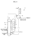
- FIG. 4 is a schematic diagram of an integrated coal gasification combined cycle plant including a coal gasifier according to a second embodiment of the present invention.
- FIG. 5 is a schematic diagram of an integrated coal gasification combined cycle plant including a coal gasifier according to a third embodiment of the present invention.
- a first embodiment of an integrated coal gasification combined cycle plant to which a coal gasifier unit according to the present invention is applied will be described below with reference to FIG. 1 .
- FIG. 1 is a schematic diagram of the integrated coal gasification combined cycle plant including the coal gasifier unit according to this embodiment.
- an integrated coal gasification combined cycle (IGCC) plant 1 mainly includes a coal gasifier (carbon-containing fuel gasifier) 3 that gasifies coal (fuel containing carbon), a gas turbine system 5 to which a synthetic gas output from the coal gasifier 3 is directed, a generator G that generates electrical power as a gas turbine 5 b of the gas turbine system 5 and a steam turbine (not shown) connected to the same rotating shaft 5 d as the gas turbine 5 b are rotated, and a heat recovery steam generator (HRSG) 11 to which combustion gas that has passed through the gas turbine system 5 is directed.
- a coal gasifier carbon-containing fuel gasifier
- a gas turbine system 5 to which a synthetic gas output from the coal gasifier 3 is directed
- a generator G that generates electrical power as a gas turbine 5 b of the gas turbine system 5 and a steam turbine (not shown) connected to the same rotating shaft 5 d as the gas turbine 5 b are rotated
- HRSG heat recovery steam generator
- a coal feed system (not shown) that feeds pulverized coal (fuel) to the coal gasifier 3 is disposed upstream of the coal gasifier 3 .
- This coal feed system includes a pulverizer (not shown) that pulverizes raw coal into pulverized coal measuring several micrometers to several hundreds of micrometers.
- the pulverized coal pulverized by the pulverizer is stored in a plurality of hoppers (not shown).
- the pulverized coal stored in each of the hoppers is transported to the coal gasifier 3 in predetermined amounts together with nitrogen fed from an air separator (not shown).
- the coal gasifier 3 includes a coal gasifier unit (gasifier unit) 3 a configured such that gas flows from the bottom to the top thereof and a water-cooled wall duct (coolant wall) 3 b into which the coal gasifier unit 3 a is built.
- the coolant wall is not necessarily a water-cooled wall duct but may be a water-cooled jacket or a heat exchanger installed in the gas channel.
- the coal gasifier unit 3 a has the perimeter thereof surrounded by the water-cooled wall duct 3 b , to which water is directed as a coolant, and includes, in order from the bottom thereof, a combustor 13 and a reductor 14 .
- the combustor 13 is a part that combusts a portion of pulverized coal and char while releasing the remainder as volatile components (carbon monoxide, hydrogen, and lower hydrocarbons) by pyrolysis.
- the combustor 13 uses an entrained bed; however, it may use a fluidized bed or a fixed bed.
- the combustor 13 and the reductor 14 are provided with a combustor burner (not shown) and a reductor burner (not shown), respectively, to which pulverized coal is fed from the coal feed system.
- the combustor burner is fed with air from an air booster (not shown) together with oxygen separated by the air separator as gasifying agents (oxidants).
- the combustor burner is fed with air with an adjusted oxygen concentration.
- the reductor 14 gasifies pulverized coal with high-temperature gas from the combustor 13 .
- a synthetic gas which is a gasified-coal gas containing gas fuels such as carbon monoxide and hydrogen, is produced from the pulverized coal.
- the coal gasification reaction is an endothermic reaction in which the carbon in the pulverized coal and char reacts with carbon dioxide and water in the high-temperature gas to produce carbon monoxide and hydrogen.
- the coal gasifier unit 3 a causes the pulverized coal to react with feed air fed from an air compressor 5 c disposed in the gas turbine system 5 to produce a synthetic gas (gasified-coal gas).
- a heat exchanger unit 3 c is disposed downstream of the coal gasifier unit 3 a and has a plurality of heat exchangers (not shown) installed therein. This heat exchanger unit 3 c receives sensible heat from the high-temperature gas directed from the reductor 14 and produces steam from water directed to the heat exchangers.
- the synthetic gas that has passed through the heat exchanger unit 3 c is directed to a char collector 9 .
- This char collector 9 includes a porous filter (not shown) and captures and collects char contained in the synthetic gas as the synthetic gas passes through the porous filter.
- the captured char is deposited on the porous filter to form a char layer.
- the char layer contains concentrated Na and K from the synthetic gas, which results in the removal of the Na and K in the char collector 9 .
- the thus-collected char is returned to and recycled by the combustor burner of the coal gasifier 3 together with nitrogen separated by the air separator.
- the Na and K returned to the combustor burner together with the char are discharged from below the coal gasifier unit 3 a together with finally molten pulverized coal ash.
- the discharged molten ash is rapidly cooled with water and is pulverized to yield glassy slag.
- the synthetic gas that has passed through the char collector 9 contains sulfur compounds such as carbonyl sulfide as well as carbon monoxide, hydrogen, and hydrogen sulfide. To remove such sulfur compounds, the synthetic gas is directed to and purified by a gas purifier 10 .
- the synthetic gas purified by the gas purifier 10 is fed as a fuel gas to a gas turbine combustor 5 a of the gas turbine system 5 .
- the gas turbine system 5 includes the gas turbine combustor 5 a , which combusts the fuel gas, i.e., the synthetic gas, the gas turbine 5 b , which is rotated by combustion gas produced when the gas turbine combustor 5 a combusts the synthetic gas, and the air compressor 5 c , which pumps high-pressure air to the gas turbine combustor 5 a .
- the gas turbine 5 b and the air compressor 5 c are connected with the same rotating shaft 5 d , and air compressed by the air compressor 5 c is directed to the air booster described above as well as to the gas turbine combustor 5 a .
- the combustion gas that has passed through the gas turbine 5 b is directed to the heat recovery steam generator 11 .
- a steam turbine is connected to the same rotating shaft 5 d as the gas turbine system 5 , forming a single-shaft combined system.
- the steam turbine is fed with high-pressure steam from the coal gasifier 3 and the heat recovery steam generator 11 .
- the gas turbine system 5 is not necessarily a single-shaft combined system but may be a double-shaft combined system.
- the generator G which produces electrical power, is disposed on the rotating shaft 5 d , which is driven by the gas turbine 5 b and the steam turbine.
- the generator G may be disposed at any position where it can produce electric power from the rotating shaft 5 d.
- the combustion gas that has passed through the gas turbine 5 b is directed to the heat recovery steam generator 11 to produce steam to be fed to the steam turbine.
- the combustion gas that has been used to produce steam is directed from the heat recovery steam generator 11 to a funnel 12 and is released from the funnel 12 into the atmosphere.
- Raw coal is pulverized by the pulverizer and is directed to and stored in the hoppers.
- the pulverized coal stored in the hoppers is fed to the reductor burner and the combustor burner of the coal gasifier 3 together with nitrogen separated by the air separator.
- the combustor burner is fed not only with the pulverized coal, but also with char collected by the char collector 9 .
- the gas used for combustion by the combustor burner is compressed air bled from the air compressor 5 c disposed in the gas turbine system 5 , further pressurized by the air booster, and mixed with oxygen separated by the air separator.
- the combustor 13 partially combusts the pulverized coal and char with the combustion air and pyrolyzes the remainder into volatile components (carbon monoxide, hydrogen, and lower hydrocarbons).
- the reductor 14 gasifies the pulverized coal fed from the reductor burner and the char that has released volatile components in the combustor 13 with the high-temperature gas rising from the combustor 13 to produce a combustible synthetic gas containing carbon monoxide and hydrogen.
- Water flowing through the water-cooled wall duct 3 b of the coal gasifier 3 absorbs heat from the synthetic gas passing through the reductor 14 , and the synthetic gas is directed to the heat exchanger unit 3 c disposed downstream of the coal gasifier unit 3 a .
- the synthetic gas directed to the heat exchanger unit 3 c releases its sensible heat to the individual heat exchangers to produce steam.
- the steam produced by the heat exchanger unit 3 c is mainly used to drive the steam turbine.
- the synthetic gas that has passed through the heat exchanger unit 3 c is directed to the char collector 9 , which collects char therefrom. In the char collector 9 , the Na and K in the synthetic gas are concentrated and taken into the char. The collected char containing Na and K is returned to the coal gasifier unit 3 a.
- the synthetic gas that has passed through the char collector 9 is directed to the gas turbine combustor 5 a disposed in the gas turbine system 5 and is combusted with compressed air fed from the air compressor 5 c . This combustion produces combustion gas, which rotates the gas turbine 5 b to drive the rotating shaft 5 d.
- the combustion gas that has passed through the gas turbine 5 b is directed to the heat recovery steam generator 11 , which produces steam by unit of waste heat from the combustion gas.
- the steam produced by the heat recovery steam generator 11 is mainly used to rotate the steam turbine.
- the steam turbine is rotated by the steam from the coal gasifier 3 and the steam from the heat recovery steam generator 11 to drive the rotating shaft 5 d of the gas turbine system 5 .
- the torque of the rotating shaft 5 d driven by the steam turbine is converted into electrical output power by the generator G.
- FIG. 4 shows the structure of the coal gasifier 3 .
- the second embodiment differs from the first embodiment shown in FIG. 1 in that it has a structure in which the coal gasifier 3 includes a steam drum 3 d .
- the other structure is the same as that of the first embodiment shown in FIG. 1 ; therefore, the same components are labeled with the same reference signs, and a description thereof is omitted.
- the coolant i.e., water
- the coolant is fed to the steam drum 3 d and is circulated through the steam drum 3 d , the water-cooled wall duct 3 b , and the heat exchanger unit 3 c , and only steam produced by sensible heat from the synthetic gas in the water-cooled wall duct 3 b and the heat exchanger unit 3 c is directed downstream of the steam drum 3 d .
- the resulting steam is mainly used to drive the steam turbine.
- FIG. 5 shows the structure of the coal gasifier 3 .
- the third embodiment differs from the first embodiment shown in FIG. 1 in that it has a structure in which the coal gasifier unit 3 a has a gasifier heat exchanger unit 3 e , through which the coolant, i.e., water, flows, disposed in the gas channel thereof.
- the gasifier heat exchanger unit 3 e has a plurality of heat exchangers (not shown) installed therein.
- the coal gasifier 3 may include the water-cooled wall duct 3 b .
- the other structure is the same as that of the first embodiment shown in FIG. 1 ; therefore, the same components are labeled with the same reference signs, and a description thereof is omitted.
- FIG. 2 is a block diagram showing a method for correcting the amount of heat generated from the synthetic gas produced by the coal gasifier 3 shown in FIGS. 1, 4, and 5 .
- FIG. 3 is a graph with the vertical axis indicating the amount of heat absorbed by the water passing through the water-cooled wall duct 3 b of the coal gasifier 3 and the horizontal axis indicating the operating load command to the coal gasifier 3 .
- the setting value of the amount of heat absorbed in FIG. 3 refers to the relationship between the amount of heat absorbed and the operating load when the amount of heat generated from the synthetic gas produced by the coal gasifier 3 becomes stable.
- the amount of pulverized coal charged (the amount of fuel fed) into the coal gasifier 3 is adjusted by a pulverized coal flow valve (not shown) that is disposed on a feed pipe (not shown) through which the pulverized coal is fed to the coal gasifier 3 and that controls the amount of pulverized coal charged to the coal gasifier 3 .
- a controller (not shown) disposed in the coal gasifier 3 operates the pulverized coal flow valve to control the amount of pulverized coal charged into the coal gasifier 3 depending on the amount of heat absorbed by the water directed to the water-cooled wall duct 3 b of the coal gasifier 3 .
- the controller calculates a coal gasifier input command value (gasifier input command value) from the setting value of the output power of the generator G.
- the controller also determines the setting value of the amount of heat absorbed by the coolant, i.e., the setting value of the amount of heat absorbed by the water, corresponding to the operating load command to the coal gasifier 3 from the graph in FIG. 3 .
- the first embodiment shown in FIG. 1 measures the flow meter of the feedwater at the inlet of the water-cooled wall duct 3 b of the coal gasifier 3 or the flow meter of the steam at the outlet of the water-cooled wall duct 3 b , the temperatures of the water at the inlet and the outlet of the water-cooled wall duct 3 b , and the pressures at the inlet and the outlet of the water-cooled wall duct 3 b.
- the flow rate of the feedwater at the inlet of the steam drum 3 d or the flow rate of the steam at the outlet of the steam drum 3 d , the temperatures at the inlet and the outlet of the steam drum 3 d , and the pressures at the inlet and the outlet of the steam drum 3 d are measured.
- the flow rate of the feedwater at the inlet of the gasifier heat exchanger unit 3 e or the flow rate of the steam at the outlet of the gasifier heat exchanger unit 3 e , the temperatures at the inlet and the outlet of the gasifier heat exchanger unit 3 e , and the pressures at the inlet and the outlet of the gasifier heat exchanger unit 3 e are measured.
- the difference between the measured temperatures of the water at the inlet and the outlet, the measured flow rate of the water at the inlet or the outlet, the measured pressures of the water at the inlet and the outlet, and the specific heat are used to calculate the amount of heat absorbed by the coolant shown in FIG. 2 , i.e., the actual amount of heat absorbed by the water. Specifically, the amount of heat absorbed is calculated by multiplying the change in enthalpy by the flow rate. To determine the change in enthalpy, the enthalpies at the inlet and the outlet need to be determined; therefore, the temperatures at the inlet and the outlet, the pressures at the inlet and the outlet, and the specific heat are needed. The flow rate needs only to be measured at the inlet or the outlet.
- the flow rate of the feedwater at the inlet of the steam drum 3 d or the flow rate of the steam at the outlet of the steam drum 3 d can be handled as the amount of heat absorbed because the saturation temperature is constant. Because the change in the amount of heat absorbed can be detected by comparing the calculated amount of heat absorbed by the coolant with the setting value of the amount of heat absorbed by the coolant determined from the graph in FIG. 3 , an amount-of-generated-heat correction coefficient is calculated by performing a comparison and arithmetic on the measured amount of heat absorbed and the setting value of the amount of heat absorbed.
- the coal gasifier input command value described above is corrected to calculate the amount of pulverized coal charged into the coal gasifier 3 .
- the degree of opening of the pulverized coal flow valve is controlled so that the calculated amount of pulverized coal is charged into the coal gasifier 3 .
- the integrated coal gasification combined cycle plant 1 and the control method thereof according to this embodiment provide the following advantageous effects.
- the amount of pulverized coal charged into the coal gasifier 3 is controlled depending on the change in the amount of heat generated from the synthetic gas determined from the change in the amount of heat absorbed by the water (coolant) fed to the water-cooled wall duct (coolant wall) 3 b based on the amount of heat absorbed by the water directed to the water-cooled wall duct 3 b of the coal gasifier (carbon-containing fuel gasifier) 3 corresponding to the operating load command to the coal gasifier 3 .
- the change in the amount of heat absorbed by the water directed to the coal gasifier 3 is determined from factors that correlate with the amount of heat absorbed by the water. This allows the coal gasifier 3 to be controlled before the synthetic gas reaches the gas turbine combustor 5 a disposed downstream of the coal gasifier 3 . As a result, the time delay in the control of the amount of pulverized coal charged into the coal gasifier 3 , depending on the condition of the synthetic gas output from the coal gasifier 3 or the output power of the generator G, can be reduced. Thus, the amount of heat generated from the synthetic gas output from the coal gasifier 3 and directed to the gas turbine combustor 5 a can be kept substantially constant.
- the amount of heat absorbed by the water is determined using, as the factors that correlate with the amount of heat absorbed, the flow meter of the feedwater at the inlet of the water-cooled wall duct 3 b of the coal gasifier 3 or the flow meter of the steam at the outlet of the water-cooled wall duct 3 b , the temperatures of the water at the inlet and the outlet of the water-cooled wall duct 3 b , and the pressures at the inlet and the outlet of the water-cooled wall duct 3 b .
- This allows a change in the amount of heat generated from the synthetic gas output from the coal gasifier 3 to be detected earlier to control the amount of pulverized coal charged into the coal gasifier 3 .
- the amount of heat generated from the synthetic gas output from the coal gasifier 3 and directed to the gas turbine combustor 5 a can be kept substantially constant.
- the amount of heat absorbed is determined using, as the factors that correlate with the amount of heat absorbed, the flow rate of the feedwater at the inlet of the steam drum 3 d or the flow rate of the steam at the outlet of the steam drum 3 d , the temperatures at the inlet and the outlet of the steam drum 3 d , and the pressures at the inlet and the outlet of the steam drum 3 d .
- the flow rate of the feedwater at the inlet of the steam drum 3 d or the flow rate of the steam at the outlet of the steam drum 3 d can be handled as the amount of heat absorbed because the saturation temperature is constant.
- the amount of heat absorbed is determined using, as the factors that correlate with the amount of heat absorbed, the flow rate of the feedwater at the inlet of the gasifier heat exchanger unit 3 e or the flow rate of the steam at the outlet of the gasifier heat exchanger unit 3 e , the temperatures at the inlet and the outlet of the gasifier heat exchanger unit 3 e , and the pressures at the inlet and the outlet of the gasifier heat exchanger unit 3 e.
- the graph of this embodiment shown in FIG. 3 which shows the relationship between the amount of heat absorbed by the coolant and the operating load on the coal gasifier 3 , may be corrected depending on the properties (type) of coal (pulverized coal) and the amount of gasifying agent charged into the coal gasifier 3 .
- the operating load on the coal gasifier 3 may be replaced with the output power of the gas turbine 5 b or the operating load on the entire integrated coal gasification combined cycle plant 1 .
- the fuel may instead be refuse containing carbon or scrap tires.
Landscapes
- Chemical & Material Sciences (AREA)
- Engineering & Computer Science (AREA)
- Combustion & Propulsion (AREA)
- Oil, Petroleum & Natural Gas (AREA)
- Organic Chemistry (AREA)
- Mechanical Engineering (AREA)
- General Engineering & Computer Science (AREA)
- Engine Equipment That Uses Special Cycles (AREA)
Abstract
Description
- 1 integrated coal gasification combined cycle plant (gas turbine power plant)
- 3 coal gasifier (carbon-containing fuel gasifier)
- 3 a coal gasifier unit (gasifier unit)
- 3 b water-cooled wall duct (coolant wall)
- 3 c heat exchanger unit
- 3 d steam drum
- 3 e gasifier heat exchanger unit
- 5 gas turbine system
- 5 a gas turbine combustor (combustor)
- 5 b gas turbine
- 5 c air compressor
- 5 d rotating shaft
- 9 char collector
- 10 gas purifier
- 11 heat recovery steam generator
- 12 funnel
- 13 combustor
- 14 reductor
- G generator (power-generating unit)
Claims (20)
Applications Claiming Priority (3)
| Application Number | Priority Date | Filing Date | Title |
|---|---|---|---|
| JP2011-229854 | 2011-10-19 | ||
| JP2011229854A JP5804888B2 (en) | 2011-10-19 | 2011-10-19 | Control method for gas turbine power plant, gas turbine power plant, control method for carbon-containing fuel gasifier, and carbon-containing fuel gasifier |
| PCT/JP2012/076758 WO2013058253A1 (en) | 2011-10-19 | 2012-10-17 | Method for controlling gas-turbine power plant, gas-turbine power plant, method for controlling oven for gasification of carbon-containing fuel, and oven for gasification of carbon-containing fuel |
Publications (2)
| Publication Number | Publication Date |
|---|---|
| US20140230451A1 US20140230451A1 (en) | 2014-08-21 |
| US9567904B2 true US9567904B2 (en) | 2017-02-14 |
Family
ID=48140899
Family Applications (1)
| Application Number | Title | Priority Date | Filing Date |
|---|---|---|---|
| US14/348,271 Expired - Fee Related US9567904B2 (en) | 2011-10-19 | 2012-10-17 | Method for controlling gas turbine power plant, gas turbine power plant, method for controlling carbon-containing fuel gasifier, and carbon-containing fuel gasifier |
Country Status (4)
| Country | Link |
|---|---|
| US (1) | US9567904B2 (en) |
| JP (1) | JP5804888B2 (en) |
| CN (1) | CN103764973B (en) |
| WO (1) | WO2013058253A1 (en) |
Families Citing this family (6)
| Publication number | Priority date | Publication date | Assignee | Title |
|---|---|---|---|---|
| JP5743093B2 (en) * | 2011-09-07 | 2015-07-01 | 三菱日立パワーシステムズ株式会社 | Slag discharge system, gasifier, and gas generator |
| JP6621310B2 (en) * | 2015-11-18 | 2019-12-18 | 三菱日立パワーシステムズ株式会社 | Gasification device, control device, combined gasification power generation facility and control method |
| JP6715800B2 (en) | 2017-06-09 | 2020-07-01 | 出光興産株式会社 | Fuel reduction rate output system, fuel reduction rate output method, and fuel reduction rate output program |
| CN108913216B (en) * | 2018-08-06 | 2023-06-09 | 唐山科源环保技术装备有限公司 | Method for controlling overpressure discharge of self-produced steam of gas producer |
| CN110041968B (en) * | 2019-05-08 | 2023-11-03 | 中国华能集团清洁能源技术研究院有限公司 | Gasifier water-cooled wall safety monitoring device and method |
| CN118517319B (en) * | 2024-05-11 | 2025-01-28 | 杭州航民江东热电有限公司 | A control method, system and storage medium for a thermal power unit |
Citations (18)
| Publication number | Priority date | Publication date | Assignee | Title |
|---|---|---|---|---|
| US4472936A (en) * | 1980-12-27 | 1984-09-25 | Hitachi, Ltd. | Method and apparatus for controlling combustion of gasified fuel |
| JPS59219390A (en) | 1983-05-27 | 1984-12-10 | Hitachi Ltd | Gasifier operation control method |
| US5050374A (en) * | 1990-08-01 | 1991-09-24 | John Hunter | Gasification/combustion system |
| US5145491A (en) | 1990-11-07 | 1992-09-08 | Gerhard Schmitt | Process of controlling the starting up of the gasification of solid fuels in a fluidized state |
| JP2000303079A (en) | 1999-04-19 | 2000-10-31 | Agency Of Ind Science & Technol | System for monitoring operation of gasifier |
| US6226976B1 (en) * | 1999-02-26 | 2001-05-08 | Alliedsignal, Inc. | Variable fuel heating value adaptive control for gas turbine engines |
| JP2002146366A (en) | 2000-11-14 | 2002-05-22 | Babcock Hitachi Kk | Self-learning fuzzy controlling method for coal gasification unit |
| JP2002167583A (en) | 2000-11-29 | 2002-06-11 | Babcock Hitachi Kk | Method for controlling coal gasification apparatus |
| US6609378B2 (en) * | 2002-01-17 | 2003-08-26 | Honeywell International Inc. | Energy based fuel control system for gas turbine engines running on multiple fuel types |
| JP2004018703A (en) | 2002-06-18 | 2004-01-22 | Mitsubishi Heavy Ind Ltd | Operation control method for gasification furnace of combined coal gasification power plant |
| JP2010285564A (en) | 2009-06-12 | 2010-12-24 | Mitsubishi Heavy Ind Ltd | Coal gasification furnace, method and program for controlling the same, and coal gasification combined power generator equipped with the furnace |
| US8343242B2 (en) * | 2006-06-30 | 2013-01-01 | Babcock & Wilcox Vølund A/S | Method of controlling an apparatus for generating electric power and apparatus for use in said method |
| US8381506B2 (en) * | 2009-03-10 | 2013-02-26 | General Electric Company | Low heating value fuel gas blending control |
| US8888872B2 (en) * | 2010-07-06 | 2014-11-18 | General Electric Company | Gasifier cooling system |
| US9003764B2 (en) * | 2011-12-16 | 2015-04-14 | General Electric Company | System and method for thermal control in a gas turbine engine |
| US9017435B2 (en) * | 2010-10-08 | 2015-04-28 | General Electric Company | Gasifier monitor and control system |
| US9290708B2 (en) * | 2012-01-18 | 2016-03-22 | General Electric Company | Gasification system and method for gasifying a fuel |
| US9447337B2 (en) * | 2011-08-19 | 2016-09-20 | General Electric Company | Fuel slurry heating system and method |
Family Cites Families (1)
| Publication number | Priority date | Publication date | Assignee | Title |
|---|---|---|---|---|
| CN2816046Y (en) * | 2005-08-11 | 2006-09-13 | 梅安华 | Coal-ash gasifying furnace |
-
2011
- 2011-10-19 JP JP2011229854A patent/JP5804888B2/en not_active Expired - Fee Related
-
2012
- 2012-10-17 US US14/348,271 patent/US9567904B2/en not_active Expired - Fee Related
- 2012-10-17 CN CN201280039266.6A patent/CN103764973B/en not_active Expired - Fee Related
- 2012-10-17 WO PCT/JP2012/076758 patent/WO2013058253A1/en not_active Ceased
Patent Citations (18)
| Publication number | Priority date | Publication date | Assignee | Title |
|---|---|---|---|---|
| US4472936A (en) * | 1980-12-27 | 1984-09-25 | Hitachi, Ltd. | Method and apparatus for controlling combustion of gasified fuel |
| JPS59219390A (en) | 1983-05-27 | 1984-12-10 | Hitachi Ltd | Gasifier operation control method |
| US5050374A (en) * | 1990-08-01 | 1991-09-24 | John Hunter | Gasification/combustion system |
| US5145491A (en) | 1990-11-07 | 1992-09-08 | Gerhard Schmitt | Process of controlling the starting up of the gasification of solid fuels in a fluidized state |
| US6226976B1 (en) * | 1999-02-26 | 2001-05-08 | Alliedsignal, Inc. | Variable fuel heating value adaptive control for gas turbine engines |
| JP2000303079A (en) | 1999-04-19 | 2000-10-31 | Agency Of Ind Science & Technol | System for monitoring operation of gasifier |
| JP2002146366A (en) | 2000-11-14 | 2002-05-22 | Babcock Hitachi Kk | Self-learning fuzzy controlling method for coal gasification unit |
| JP2002167583A (en) | 2000-11-29 | 2002-06-11 | Babcock Hitachi Kk | Method for controlling coal gasification apparatus |
| US6609378B2 (en) * | 2002-01-17 | 2003-08-26 | Honeywell International Inc. | Energy based fuel control system for gas turbine engines running on multiple fuel types |
| JP2004018703A (en) | 2002-06-18 | 2004-01-22 | Mitsubishi Heavy Ind Ltd | Operation control method for gasification furnace of combined coal gasification power plant |
| US8343242B2 (en) * | 2006-06-30 | 2013-01-01 | Babcock & Wilcox Vølund A/S | Method of controlling an apparatus for generating electric power and apparatus for use in said method |
| US8381506B2 (en) * | 2009-03-10 | 2013-02-26 | General Electric Company | Low heating value fuel gas blending control |
| JP2010285564A (en) | 2009-06-12 | 2010-12-24 | Mitsubishi Heavy Ind Ltd | Coal gasification furnace, method and program for controlling the same, and coal gasification combined power generator equipped with the furnace |
| US8888872B2 (en) * | 2010-07-06 | 2014-11-18 | General Electric Company | Gasifier cooling system |
| US9017435B2 (en) * | 2010-10-08 | 2015-04-28 | General Electric Company | Gasifier monitor and control system |
| US9447337B2 (en) * | 2011-08-19 | 2016-09-20 | General Electric Company | Fuel slurry heating system and method |
| US9003764B2 (en) * | 2011-12-16 | 2015-04-14 | General Electric Company | System and method for thermal control in a gas turbine engine |
| US9290708B2 (en) * | 2012-01-18 | 2016-03-22 | General Electric Company | Gasification system and method for gasifying a fuel |
Non-Patent Citations (5)
| Title |
|---|
| Decision to Grant a Patent issued Aug. 4, 2015 in corresponding Japanese patent application No. 2011-229854. |
| International Search Report issued Dec. 25, 2012 in International Application No. PCT/JP2012/076758. |
| Notification of Grant of Invention Patent issued Jan. 20, 2016 in corresponding Chinese patent application No. 201280039266.6 (with English translation). |
| Office Action issued Jun. 2, 2015 in corresponding Chinese patent application No. 201280039266.6 (with English translation). |
| Written Opinion of the International Searching Authority issued Dec. 25, 2012 in International Application No. PCT/JP2012/076758. |
Also Published As
| Publication number | Publication date |
|---|---|
| WO2013058253A1 (en) | 2013-04-25 |
| JP2013087702A (en) | 2013-05-13 |
| US20140230451A1 (en) | 2014-08-21 |
| JP5804888B2 (en) | 2015-11-04 |
| CN103764973A (en) | 2014-04-30 |
| CN103764973B (en) | 2016-04-13 |
Similar Documents
| Publication | Publication Date | Title |
|---|---|---|
| RU2438028C2 (en) | Electro-station of combined cycle with inter-cycle gasification (versions), control device for such electro-station (versions) and control procedure for such electro-station | |
| US9261020B2 (en) | Integrated coal gasification combined cycle plant | |
| US9567904B2 (en) | Method for controlling gas turbine power plant, gas turbine power plant, method for controlling carbon-containing fuel gasifier, and carbon-containing fuel gasifier | |
| CN101449040A (en) | Goal gasification composite power generating system, and its running control method | |
| EP2080878B1 (en) | Gas turbine power generation system and method of detecting calorific abnormality of the same | |
| JP5721317B2 (en) | Coal gasification furnace facility, control method and program thereof, and coal gasification combined power generation apparatus provided with the same | |
| KR101739678B1 (en) | Gasification power plant control device, gasification power plant, and gasification power plant control method | |
| JP4095829B2 (en) | Char circulation type coal gasification power plant system | |
| KR101735989B1 (en) | Gasification power plant control device, gasification power plant, and gasification power plant control method | |
| JP2015048840A (en) | Gasification power generation system control method | |
| JP2017110165A (en) | Gasification device, and controller for the gasification device, and gasification composite power generation equipment | |
| US20200270536A1 (en) | Gasification unit, gasification unit control device and method, and integrated gasification combined cycle | |
| JP5412205B2 (en) | Gas turbine plant and gasification fuel power generation facility equipped with the same | |
| Jaeger | Japan 250 MW coal based IGCC demo plant set for 2007 start-up | |
| JP7043285B2 (en) | How to operate gasification furnace equipment, gasification combined cycle equipment and gasification furnace equipment | |
| US20250154417A1 (en) | Gasification unit, integrated gasification combined cycle, and operating method of gasifier | |
| JP2016037593A (en) | Gasification furnace equipment, gasification composite power generating equipment, and method for controlling the gasification furnace unit | |
| JP2011185240A (en) | Gas turbine, and gasification combined power generation plant having the same |
Legal Events
| Date | Code | Title | Description |
|---|---|---|---|
| AS | Assignment |
Owner name: MITSUBISHI HITACHI POWER SYSTEMS, LTD., JAPAN Free format text: ASSIGNMENT OF ASSIGNORS INTEREST;ASSIGNORS:SHIBATA, YASUNARI;KITAGAWA, YUICHIRO;SHIBATA, KENGO;AND OTHERS;REEL/FRAME:033849/0686 Effective date: 20140127 |
|
| STCF | Information on status: patent grant |
Free format text: PATENTED CASE |
|
| MAFP | Maintenance fee payment |
Free format text: PAYMENT OF MAINTENANCE FEE, 4TH YEAR, LARGE ENTITY (ORIGINAL EVENT CODE: M1551); ENTITY STATUS OF PATENT OWNER: LARGE ENTITY Year of fee payment: 4 |
|
| AS | Assignment |
Owner name: MITSUBISHI POWER, LTD., JAPAN Free format text: CHANGE OF NAME;ASSIGNOR:MITSUBISHI HITACHI POWER SYSTEMS, LTD.;REEL/FRAME:054975/0438 Effective date: 20200901 |
|
| AS | Assignment |
Owner name: MITSUBISHI POWER, LTD., JAPAN Free format text: CORRECTIVE ASSIGNMENT TO CORRECT THE REMOVING PATENT APPLICATION NUMBER 11921683 PREVIOUSLY RECORDED AT REEL: 054975 FRAME: 0438. ASSIGNOR(S) HEREBY CONFIRMS THE ASSIGNMENT;ASSIGNOR:MITSUBISHI HITACHI POWER SYSTEMS, LTD.;REEL/FRAME:063787/0867 Effective date: 20200901 |
|
| FEPP | Fee payment procedure |
Free format text: MAINTENANCE FEE REMINDER MAILED (ORIGINAL EVENT CODE: REM.); ENTITY STATUS OF PATENT OWNER: LARGE ENTITY |
|
| LAPS | Lapse for failure to pay maintenance fees |
Free format text: PATENT EXPIRED FOR FAILURE TO PAY MAINTENANCE FEES (ORIGINAL EVENT CODE: EXP.); ENTITY STATUS OF PATENT OWNER: LARGE ENTITY |
|
| STCH | Information on status: patent discontinuation |
Free format text: PATENT EXPIRED DUE TO NONPAYMENT OF MAINTENANCE FEES UNDER 37 CFR 1.362 |
|
| FP | Lapsed due to failure to pay maintenance fee |
Effective date: 20250214 |