US9559818B2 - Communications terminal and method - Google Patents
Communications terminal and method Download PDFInfo
- Publication number
- US9559818B2 US9559818B2 US14/373,776 US201314373776A US9559818B2 US 9559818 B2 US9559818 B2 US 9559818B2 US 201314373776 A US201314373776 A US 201314373776A US 9559818 B2 US9559818 B2 US 9559818B2
- Authority
- US
- United States
- Prior art keywords
- base station
- communications
- operating
- bearer
- communications terminal
- Prior art date
- Legal status (The legal status is an assumption and is not a legal conclusion. Google has not performed a legal analysis and makes no representation as to the accuracy of the status listed.)
- Active, expires
Links
- 238000004891 communication Methods 0.000 title claims abstract description 592
- 238000000034 method Methods 0.000 title claims description 27
- 230000010354 integration Effects 0.000 claims description 9
- 238000012544 monitoring process Methods 0.000 claims description 6
- 238000010295 mobile communication Methods 0.000 abstract description 87
- 230000011664 signaling Effects 0.000 description 36
- 238000005259 measurement Methods 0.000 description 18
- 238000010586 diagram Methods 0.000 description 9
- 230000005540 biological transmission Effects 0.000 description 6
- 230000007774 longterm Effects 0.000 description 4
- 238000004458 analytical method Methods 0.000 description 1
- 230000001143 conditioned effect Effects 0.000 description 1
- 230000001419 dependent effect Effects 0.000 description 1
- 238000012986 modification Methods 0.000 description 1
- 230000004048 modification Effects 0.000 description 1
- 238000012360 testing method Methods 0.000 description 1
- 230000035899 viability Effects 0.000 description 1
Images


Classifications
-
- H—ELECTRICITY
- H04—ELECTRIC COMMUNICATION TECHNIQUE
- H04L—TRANSMISSION OF DIGITAL INFORMATION, e.g. TELEGRAPHIC COMMUNICATION
- H04L5/00—Arrangements affording multiple use of the transmission path
- H04L5/003—Arrangements for allocating sub-channels of the transmission path
- H04L5/0032—Distributed allocation, i.e. involving a plurality of allocating devices, each making partial allocation
-
- H—ELECTRICITY
- H04—ELECTRIC COMMUNICATION TECHNIQUE
- H04W—WIRELESS COMMUNICATION NETWORKS
- H04W76/00—Connection management
- H04W76/10—Connection setup
- H04W76/15—Setup of multiple wireless link connections
-
- H—ELECTRICITY
- H04—ELECTRIC COMMUNICATION TECHNIQUE
- H04W—WIRELESS COMMUNICATION NETWORKS
- H04W28/00—Network traffic management; Network resource management
- H04W28/16—Central resource management; Negotiation of resources or communication parameters, e.g. negotiating bandwidth or QoS [Quality of Service]
-
- H—ELECTRICITY
- H04—ELECTRIC COMMUNICATION TECHNIQUE
- H04W—WIRELESS COMMUNICATION NETWORKS
- H04W16/00—Network planning, e.g. coverage or traffic planning tools; Network deployment, e.g. resource partitioning or cells structures
- H04W16/24—Cell structures
-
- H—ELECTRICITY
- H04—ELECTRIC COMMUNICATION TECHNIQUE
- H04W—WIRELESS COMMUNICATION NETWORKS
- H04W24/00—Supervisory, monitoring or testing arrangements
-
- H—ELECTRICITY
- H04—ELECTRIC COMMUNICATION TECHNIQUE
- H04W—WIRELESS COMMUNICATION NETWORKS
- H04W24/00—Supervisory, monitoring or testing arrangements
- H04W24/08—Testing, supervising or monitoring using real traffic
-
- H—ELECTRICITY
- H04—ELECTRIC COMMUNICATION TECHNIQUE
- H04W—WIRELESS COMMUNICATION NETWORKS
- H04W72/00—Local resource management
- H04W72/04—Wireless resource allocation
-
- H04W72/042—
-
- H04W72/085—
-
- H—ELECTRICITY
- H04—ELECTRIC COMMUNICATION TECHNIQUE
- H04W—WIRELESS COMMUNICATION NETWORKS
- H04W72/00—Local resource management
- H04W72/20—Control channels or signalling for resource management
- H04W72/23—Control channels or signalling for resource management in the downlink direction of a wireless link, i.e. towards a terminal
-
- H—ELECTRICITY
- H04—ELECTRIC COMMUNICATION TECHNIQUE
- H04W—WIRELESS COMMUNICATION NETWORKS
- H04W72/00—Local resource management
- H04W72/50—Allocation or scheduling criteria for wireless resources
- H04W72/54—Allocation or scheduling criteria for wireless resources based on quality criteria
- H04W72/542—Allocation or scheduling criteria for wireless resources based on quality criteria using measured or perceived quality
-
- H04W76/02—
-
- H04W76/025—
-
- H—ELECTRICITY
- H04—ELECTRIC COMMUNICATION TECHNIQUE
- H04W—WIRELESS COMMUNICATION NETWORKS
- H04W76/00—Connection management
- H04W76/10—Connection setup
-
- H—ELECTRICITY
- H04—ELECTRIC COMMUNICATION TECHNIQUE
- H04W—WIRELESS COMMUNICATION NETWORKS
- H04W36/00—Hand-off or reselection arrangements
- H04W36/0005—Control or signalling for completing the hand-off
- H04W36/0055—Transmission or use of information for re-establishing the radio link
- H04W36/0069—Transmission or use of information for re-establishing the radio link in case of dual connectivity, e.g. decoupled uplink/downlink
- H04W36/00695—Transmission or use of information for re-establishing the radio link in case of dual connectivity, e.g. decoupled uplink/downlink using split of the control plane or user plane
-
- H—ELECTRICITY
- H04—ELECTRIC COMMUNICATION TECHNIQUE
- H04W—WIRELESS COMMUNICATION NETWORKS
- H04W36/00—Hand-off or reselection arrangements
- H04W36/16—Performing reselection for specific purposes
- H04W36/18—Performing reselection for specific purposes for allowing seamless reselection, e.g. soft reselection
-
- H—ELECTRICITY
- H04—ELECTRIC COMMUNICATION TECHNIQUE
- H04W—WIRELESS COMMUNICATION NETWORKS
- H04W36/00—Hand-off or reselection arrangements
- H04W36/24—Reselection being triggered by specific parameters
- H04W36/26—Reselection being triggered by specific parameters by agreed or negotiated communication parameters
- H04W36/28—Reselection being triggered by specific parameters by agreed or negotiated communication parameters involving a plurality of connections, e.g. multi-call or multi-bearer connections
-
- H—ELECTRICITY
- H04—ELECTRIC COMMUNICATION TECHNIQUE
- H04W—WIRELESS COMMUNICATION NETWORKS
- H04W88/00—Devices specially adapted for wireless communication networks, e.g. terminals, base stations or access point devices
- H04W88/02—Terminal devices
-
- H—ELECTRICITY
- H04—ELECTRIC COMMUNICATION TECHNIQUE
- H04W—WIRELESS COMMUNICATION NETWORKS
- H04W92/00—Interfaces specially adapted for wireless communication networks
- H04W92/16—Interfaces between hierarchically similar devices
- H04W92/20—Interfaces between hierarchically similar devices between access points
Definitions
- the present invention relates to mobile communications networks for communicating data to and/or from communications terminals, infrastructure equipment, communications terminals and methods of communicating.
- LTE Long Term Evolution
- SC-FDMA Single Carrier Frequency Division Multiple Access
- the co-operating set of base stations includes a serving base station and at least one co-operating base station.
- the serving base station is a base station to which the communications terminal is attached in the sense that control and signalling of radio bearers are established with the serving base stations as well as the S1-U and S1-MME connections with the serving gateway and mobility manager via the serving base station respectively.
- the serving base station is typically configured to control the communication of the user data to the co-operating base station via an interface between the serving base station and the co-operating base station.
- the serving base station can then control the communication of user data selectively to the communications terminals from either the serving base station or the co-operating base station or both depending on a state of a radio communications link between the co-operating base station and the communications terminals and the radio communication techniques which are used to form the wireless access interface between the base stations and the communications terminals.
- a communications terminal for communicating data to or receiving data from a mobile communications network.
- the mobile communications terminal is configured to establish in co-operation with the mobile communications network a communications bearer for communicating data for a communications session from or to the mobile communications device via the communications bearer, the communications bearer including a radio communications channel between the communications terminal and a serving base station of the mobile communications network, and to receive the data from a serving base station of the mobile communications network via a radio communications channel between the serving base station and the communications terminal, wherein the serving base station forms with at least one other co-operating base station a co-operating set.
- the communications terminal is configured to determine a state of the radio communications channel between the serving base station and the communications terminal and between the co-operating base station and the communications terminal, to communicate the determined state of the radio communications channel between the serving base station and the co-operating base station and the communications terminal to the serving base station, to receive the user data selectively from one or both of the serving base station or the co-operating base station consequent upon the communicated state of a radio communications channel established via the wireless access interface under the control of the serving base station, and consequent upon predetermined conditions, to receive the user data from the co-operating base station, which has been communicated to the co-operating base station using a communications bearer established from the core network to the co-operating base station for communicating the user data to the co-operating base station for transmitting the user data to the communications terminal.
- a mobile communications network for communicating data to and/or from one or more communications terminals.
- the mobile communications network comprises a core network part including infrastructure equipment, and a radio network part including a plurality of base stations which are configured to provide a wireless access interface for communicating the data to or from the communications terminals.
- One of the plurality of base stations is configured to operate as a serving base station to one of the communications terminals, to establish in co-operation with the communications terminal one or more communications bearers for communicating user data to or from the communications terminal via the core network part and the radio network part via the serving base station, and to co-operate with at least one other of the plurality of base stations to communicate the user data to or from the communications terminal.
- the co-operating base station is configured to receive user data for communicating to the communications terminal via an interface between the serving base station and the co-operating base station, and to transmit the user data selectively to the communications terminal consequent upon a state of a radio communications channel established via the wireless access interface under the control of the serving base station.
- the mobile communications network is configured to monitor a state of the radio communications channel between the co-operating base station and the communications terminal, and consequent upon predetermined conditions, to establish a communications bearer from the core network to the co-operating base station for communicating the user data to the co-operating base station for transmitting the user data to the communications terminal. Accordingly, a bandwidth requirement of the interface between the serving base station and the co-operating base station can be reduced.
- Embodiments of the present invention find application with a co-operating set of a plurality of base stations which co-operate in order to communicate data to a communications terminal, the co-operating set of base stations including a serving base station and at least one co-operating base station.
- the serving base station is typically a base station through which the communications terminal is currently attached to the mobile communications network and typically is a base station through which the communications terminal has either established one or more communications bearers which are used to communicate user data to or from the communications terminal or is a base station to which the communications terminal has handed over.
- the serving base station is typically configured to control the communication of the user data to the co-operating base station via an interface between the serving base station and the co-operating base station.
- the serving base station can communicate the user data to the co-operating base station and then control the communication of user data selectively to the communications terminals from either the serving base station or the co-operating base station or both depending on the state of a radio communications link between the co-operating base station and the communications terminals and the radio communication techniques which are used to form the wireless access interface between the base stations and the communications terminals.
- the interface between the serving base station and the co-operating base station is known as the X2 interface.
- the interface between the serving base station and the co-operating base station X2 interface
- the interface between the serving base station and the co-operating base station must carry scheduling assignments for transmitting the user data, control information as well as the user data to be communicated then the interface can become congested because of a limited bandwidth of the interface which is available.
- Embodiments of the present invention have therefore been devised so as to reduce and to relieve a burden on the interface between the base stations of a co-operating set of base stations. Accordingly depending on predetermined conditions being satisfied, which can include a state of the radio link between the co-operating base station and the communications terminal provided by the wireless access interface, embodiments of the present invention are arranged to establish a communications bearer from the core network to the co-operating base station (referred to for brevity as a sub-bearer) for communicating the user data to the co-operating base station without going through the serving base station.
- a communications bearer from the core network to the co-operating base station (referred to for brevity as a sub-bearer) for communicating the user data to the co-operating base station without going through the serving base station.
- the serving base station may stop transmitting the user data of the selected communications bearer via the interface between the serving base station and the co-operating base station.
- the sub-bearer from the serving gateway to the co-operating base station may be established without first communicating the user data to the serving base station and to the co-operating base station via the interface between the serving and co-operating base stations.
- a control element in the network could be a mobility manager, which decides to establish the sub-bearer from the serving gateway to the co-operating base station based on notifications from the serving base station.
- the X2 is normally configured in the system even when not used. In some situations there might be no X2 interface.
- the transmission could be a simultaneous multi-point transmission. Transmission from one base station at a time makes little sense because when the communications terminal is nomadic, the S1 based handover can be used although it may be considered better to maintain the co-operating set with the current serving base station to utilise gains from switching and macro diversity.
- FIG. 1 is a schematic block diagram of a mobile radio network and mobile communications devices forming a communication system which operates in accordance with the 3GPP Long Term Evolution (LTE) standard;
- LTE Long Term Evolution
- FIG. 2 is a schematic block diagram illustrating the operation of the mobile communications network shown in FIG. 1 when configured to operate with a co-operating set of base stations;
- FIG. 3 is an example embodiment of the present technique in which a separate communications bearer is established from the serving gateway to one of the co-operating base stations of the co-operating set shown in FIG. 2 ;
- FIG. 4 is a schematic block diagram illustrating a flow of signalling messages from a serving base station to a serving gateway and a mobility manager for the co-operating set of base stations shown in FIG. 3 ;
- FIG. 5 a is a graphical representation of a plot of signal noise ratio with respect to time for a co-operating base station showing a variation in radio channel quality
- FIG. 5 b is a graphical representation of a plot of signal to noise ratio with respect to time for a serving base station and a co-operating base station of the co-operating set illustrating a period in which the radio quality provided by the co-operating base station exceeds that of the serving base station; and FIG. 5 c is a corresponding plot to that shown in FIG. 5 b providing an example in which a signal noise radio for the co-operating base station exceeds that of the serving base station for a time which would trigger a handover to the co-operating base station;
- FIG. 6 provides a flow diagram representing the operation of the mobile communications network in providing the co-operating set in accordance with an example embodiment using C-plane signalling
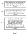
- FIG. 7 provides a flow diagram representing the operation of the mobile communications network as presented in FIG. 6 but modified to include U-plane signalling.
- FIG. 1 provides the example architecture of an LTE network.
- communications terminals (UE) 1 are arranged to communicate data to and from base stations 2 which are referred to in LTE as enhanced NodeBs (eNB).
- eNB enhanced NodeBs
- the communications terminals 1 each include a transmitter/receiver unit 3 .
- the base stations or eNB's 2 are connected to a serving gateway S-GW 6 which is arranged to perform routing and management of mobile communications services to the communications terminals 1 as they roam throughout the mobile radio network.
- a mobility management entity (MME) 8 manages the enhanced packet service (EPS) connections with the communications terminals 1 using subscriber information stored in a home subscriber server (HSS) 10 .
- Other core network components include the policy charging and resource function (PCRF) 12 a packet data gateway (P-GW) 14 which connects to an internet network 16 and finally to an external server 20 . More information may be gathered for the LTE architecture from the book entitled “ LTE for UMTS OFDM and SC - FDMA based radio access ”, Holma H. and Toskala A. page 25 ff.
- LTE/SAE terminology and names are used. However embodiments of the present technique can be applied to other mobile communications systems such as UMTS and GERAN with the GPRS core network.
- communications terminals 1 can roam throughout the mobile communications network and as with a conventional operation attach to base stations (eNB's) 2 in order to transmit and receive data via the wireless access interface provided by the base stations 2 .
- a communications terminal 1 once attached to a base station 2 may establish one or more communications bearers for transmitting or receiving user data.
- one of the communications terminals 1 . 1 has established three radio access bearers B1, B2, B3 for transmitting and receiving user data.
- the communications bearers B1, B2, B3 may be provided to different application programs providing services to a user of the communications terminal 1 . 1 .
- Each of the bearers B1, B2, B3 may be operating in accordance with a pre-determined quality of service for communicating the data via the respective communications bearer.
- the communications terminal 1 . 1 may detach from the base station 2 . 1 and re-attach to a target base station 2 . 2 in accordance with a conventional handover operation because a signal quality of a radio communications channel provided by the target base station 2 . 2 has become better than that available from the source base station 2 . 1 .
- a co-operating set of base stations comprises at least a serving base station and at least one other co-operating base station.
- the co-operating set of base stations utilises an interface between the base stations.
- this interface is known as the X2 interface.
- the communications terminal 1 . 1 shown in FIG. 1 is again being provided with three communications bearers B1, B2, B3 for communicating data which maybe in accordance with different quality of service requirements.
- the serving base station 2 . 5 in one example, is monitoring a condition of radio communications between the communications terminal 1 . 1 and the first and second co-operating base stations 2 . 3 , 2 . 4 and the serving base station 2 . 5 .
- the serving base station 2 . 5 selects either the serving base station 2 . 5 , the first co-operating base station 2 . 3 or the second co-operation base station 2 . 4 to communicate the user data via a particular one of the communications bearers. So for the example of the communications bearer B1, the co-operating base stations 2 . 3 , 2 . 4 have been selected to communicate the user data to provide the communications bearer B1 because of a current state of the radio communications link and in one example in combination with a quality of service requirement for the first communications bearer B1. In contrast the serving base station 2 . 5 may continue to communicate user data via the second and third bearers B2, B3 again perhaps because of a quality of service requirement for those communications bearers B2, B3.
- the quality of service for the communications bearers B2, B3 may require a low data rate and be delay tolerant. Accordingly, a quality of a radio communications channel for communicating the data on the B2 and B3 communications bearer may be lower so that it is not necessary to use additional diversity provided by the co-operating base stations 2 . 3 , 2 . 4 .
- the user data communicated via the first communications bearer B1 is provided either one or both of the first or the second co-operating base stations 2 . 3 , 2 . 4
- the user data is conventionally communicated via the X2 interfaces 30 , 32 to the respective first and second co-operating base stations 2 . 3 , 2 . 4 .
- Also communicated with the user data is scheduling and assignment information so that the co-operating base stations know when they are to transmit the user data via the wireless access interface to the communications terminal 1 . 1 .
- the user data maybe communicated from both the serving base station 2 . 5 as well as the first and second co-operating base stations 2 . 3 , 2 . 4 which may then be combined at the communications terminal 1 .
- the radio signals can be combined constructively at the communications terminal, which have been received from both the serving base station 2 . 5 and the co-operating base station 2 . 3 , 2 . 4 .
- the communication of the user data to the communications terminal 1 . 1 from one of the base stations in the co-operating set is controlled by the serving base station 2 . 5 in the co-operating set.
- Control of the communication of the user data is by communicating scheduling assignment indications to respective co-operating base stations 2 . 3 , 2 . 4 from the serving base station 2 . 5 , the scheduling assignment indications being communicated via the interface between the serving base station and the co-operating base stations (for example, X2 interface).
- Example embodiments of the present technique can provide an arrangement for relieving congestion on an interface (e.g. X2 interface) between a serving base station and a co-operating base station which form a co-operating set of base stations for communicating user data to a communications terminal.
- an interface e.g. X2 interface
- one of the serving base station or other parts of the mobile communications network is arranged to monitor the quality of radio communications link between the communications terminal and the serving base station and between the co-operating base station and the communications terminal.
- the mobile communications network is arranged to communicate the user data via either the co-operating base station or the serving base station or in some cases both.
- a separate communications bearer (referred to in the following description as a sub-bearer) can be established from, for example, a serving gateway of the core network to the co-operating base station for communicating user data directly to the co-operating base station, instead of, or as well as the serving base station.
- a sub-bearer can be established from, for example, a serving gateway of the core network to the co-operating base station for communicating user data directly to the co-operating base station, instead of, or as well as the serving base station.
- the co-operating base station provides only short intermittent periods for which the radio communications channel is better than the serving base station then only a small amount of user data will occasionally be communicated to the communications terminal via the co-operating base station and so it may not be efficient to establish the sub-bearer from the serving gateway to the co-operating base station compared with an amount of signalling and a time required to establish the communications bearer to the co-operating base station.
- the amount of time for which the co-operating base station is providing a better radio communications link than the serving base station is longer than the time required to establish the sub-bearer to the co-operating base station from the serving gateway then it may be a more efficient to communicate the user data separately and directly to the co-operating base station.
- the co-operating base station is providing a better radio communications channel for a significant time which is better than the serving base station then there may become a point at which it would be better for the communications terminal to hand over to the co-operating base station so that that co-operating base station then becomes the serving base station.
- the time for which the co-operating base station provides a better radio communications link quality than the serving base station is greater than a time for which a handover typically would be performed, it may make sense not to handover.
- Sub-bearers can be established to all co-operating base stations in a co-operating set from the S-GW.
- handover may not be executed even if a time for which the radio channel quality exceeds that for which a handover would be typically executed because it is possible to benefit from macro diversity as switching time will always be shorter than handover.
- a communications terminal can combine signals which are multi-cast from the co-operating base stations.
- the relative merits of establishing a separate communications bearer (sub-bearer) between the serving gateway and the co-operating base station for communicating the user data rather than via the interface between the serving base station and the co-operating base station will depend on a relative quality or service which is required for the communication of the user data.
- FIG. 3 provides a schematic block diagram of the co-operating set of base stations shown in FIG. 2 that has been adapted in accordance with the present technique. More specifically according to one example the mobile communications network is adapted to provide a separate communications bearer for conveying user data to one or both of the co-operating base stations 2 . 3 , 2 . 4 without going through the serving base station 2 . 5 and the X2 interface.
- the separate communications interface (e.g. X2) 30 , 32 therefore fulfils the requirement for the communications bearer B1 via the S1_u interface between the serving gateway 6 and a first of co-operating base stations 2 . 3 and the second co-operating base stations 2 . 4 .
- the mobile communications network assesses whether it would be more efficient in terms of communication resources used and time taken to establish a separate communications bearers with respect to a stability of the radio communications link between the co-operating base stations 2 . 3 , 2 . 4 and the communications terminal 1 . 1 .
- the present technique in order to reduce a burden on an interface between the serving base station 2 . 5 and the co-operating base stations 2 . 3 , 2 . 4 via for example the X2 interface according to the LTE Standard, the present technique arranges for a separate communications bearer to be established between the serving gateway 6 and one or more of the co-operating base stations 2 . 3 , 2 . 4 via the S1_u interface.
- a separate bearer is established between the serving gateway 6 and the co-operating base station 2 . 3 and/or the second co-operating base station 2 . 4 .
- the separate communications bearer which is established between the serving gateway 2 . 3 and a co-operating base station of the co-operating set for conveying the user data in accordance with a communications bearer to the communications terminal will be referred to as a “sub-bearer”.
- the sub-bearer conveys the data for fulfilling the communications bearer B1 for communicating user data via the co-operating base station 2 . 3 , 2 . 4 .
- this sub-bearer is also via the S1_u interface between the serving gateway 6 and the co-operating base station 2 . 3 and otherwise represents a communications bearer which would be established between the serving gateway 6 and any other base station 2 .
- the cost function for establishing the sub-bearer B1 is in terms of signalling and communications bandwidth and delay in establishing the sub-bearer.
- the decision to establish to establish the sub-bearer is done by the mobility management entity (MME) 8 based on reports of radio link quality measurements from the serving station 2 . 5 .
- MME mobility management entity
- FIG. 4 a schematic block diagram is provided of the co-operating set of base stations which reflects the arrangement shown in FIG. 3 but has been provided to illustrate the signalling requirements in order to make a determination as to whether or not the sub-bearer B1 should be established.
- the serving base station 2 . 5 collects information relating to a relative quality of a current radio communications between the co-operating base stations 2 . 3 , 2 . 4 and the mobile communications terminal 1 . 1 as well as a quality of the radio communications between the serving base station 2 . 5 and the communications terminal 1 . 1 . Conventionally, this information is only used to control the communication from the co-operating base station 2 . 3 .
- the measurement reports are communicated to the MME 8 .
- the MME 8 then establishes the S1_u sub-bearers between the serving gateway 6 and the co-operating base station 2 . 3 .
- the pre-determined conditions include at least a relative quality of the radio communications links between the co-operating base stations 2 . 3 , 2 . 4 and the communications terminal 1 . 1 with respect to a quality of the radio communications links between the serving base station 2 . 5 and the communications terminal 1 . 1 .
- the decision criteria will be explained in more detail in the following paragraphs with reference to FIGS. 5 a , 5 b and 5 c.
- FIG. 5 a provides a graphical plot of signal to noise ratio with respect to time for a co-operating base station. As can be seen in FIG. 5 a an average value of the signal to noise ratio is shown with respect to the plot in which for periods of t1 and t2 the signal to noise ratio exceeds the average value.
- the predetermined conditions or criteria for establishing the S1_u sub-bearer for the communications bearer B1 may include a determination of the rate of change of the signal to noise ratio, when this is below a pre-determined value. If the signal to noise ratio is changing rapidly then the radio communications quality may not be at a level for a duration for which it will be worthwhile establishing the sub-bearer B1 from the serving gateway 6 to the co-operating base station 2 . 3 . However, if the rate of change is slow enough, and the average signal to noise ratio is above a predetermined level, then it can be assumed that at some point the signal to noise ratio will remain above a value for which communications can be relied upon from the co-operating base station 2 . 3 to the communications terminal 1 .
- This first example of the criteria for establishing the sub-bearer therefore represents a relatively coarse test of viability of the S1_u sub-bearer.
- the serving base station 2 . 5 continues to monitor the radio communications link quality from the co-operating base station 2 . 3 to the communications terminal 1 . 1 .
- the user data can be communicated via the co-operating base station 2 . 3 , for which the sub-bearer can be used from the serving gateway 6 to the co-operating base station 2 . 3 , instead of or in addition to the communications bearer B1 from the serving gateway 6 to the serving base station 2 . 5 .
- observation time for which the state of the radio communications channel can be observed to determine whether to establish the sub-bearer.
- This observation time may depend on the quality of service requirement for the communications bearer and also a confidence level required. The greater the observation time the greater is a confidence probability that the sub-bearer will be used efficiently compared with the saving on the interface between the serving base station and the co-operating base station.
- FIG. 5 b A further example of determining the criteria for establishing the sub-bearer via the co-operating base station 2 . 3 is shown in FIG. 5 b .
- a plot of signal to noise ratio with respect to time is shown for a serving base station and a co-operating base station 52 .
- the MME as shown in FIG. 4 may receive reports from the serving base station of the signal noise ratio of the serving base station and the co-operating base station 2 . 3 , 2 . 4 with respect to time.
- FIG. 5 b for a period tc1 the signal noise ratio of the radio communications channel between the co-operating base station 2 . 3 , 2 . 4 and the communications terminal 1 .
- the MME 8 concludes that it is worth establishing the sub-bearer B1 to the co-operating base station C1 eNB 2 . 3 and communicating the user data via the sub-bearer B1 from the serving gateway to the co-operating base station 2 . 3 .
- the measured time tc1 for which the radio link quality is better via the co-operating base station is compared with the set-up time for establishing the sub-bearer S1_u.
- the set-up time can be determined from a time taken to measure the signal to noise ratio from the co-operating base station 2 . 3 and the serving base station 2 . 5 to the communications terminal 1 . 1 , a time to report this measurement to the MME 8 and a time to establish the sub-bearer S1_u.
- the set up time includes a time taken to acquire the measurements of the signal noise ratio from the serving base station 2 . 5 to the communications terminal 1 . 1 and from the co-operating base station 2 . 3 to the communications terminal 1 .
- FIG. 5 c provides a plot of signal to noise ratio with respect to time for the serving base station 54 and the co-operating base station 56 .
- the signal to noise ratio of the co-operating base station 2 . 3 exceeds that of the serving base station 2 . 5 .
- the time tc2 is relatively long and given that this time exceeds a time for performing a handover then in this case the communications terminal or the mobile communications network, for example, the MME 8 , may determine that the communications terminal 1 . 1 should handover to the co-operating base station 2 . 3 .
- the time required to execute handover comprises a handover preparation time, a handover execution time and a handover completion time which includes the communication of signalling messages as well as reserving radio communications resources on the co-operating base station. If this total handover time is less than a time tc2 in which the co-operating base station provides a better radio communications link quality than the serving base station then the MME 8 may decide not to establish the sub-bearer B1 but to instruct the communications terminal to handover to the co-operating base station. In this case a sub-bearer for the communications bearer B1 will be established via the S1 interface as the co-operating base station becomes the new serving base station. However as mentioned above, it may be preferable to maintain the co-operating set even though th hand over condition is satisfied.
- FIG. 4 provides an illustration for explaining the options for communicating signalling messages in accordance with the present technique.
- signalling messages may be communicated as dedicated signalling messages via the C-plane, in which case the serving base station 2 . 5 communicates the signalling messages to the MME 8 via the S1_MME interface.
- the MME 8 may then make a decision to establish a dedicated sub-bearer from the serving gateway 6 to the co-operating base station 2 . 3 , 2 . 4 , which is signalled to the serving gateway 6 via the S11 interface 40 .
- the two headed arrows 40 , 42 shown in FIG. 4 represent the communication of signalling messages via the C-plane.
- the mobile communications network is configured to monitor respectively the state of the radio communications channel between the serving base station 2 . 5 and the communications terminal 1 . 1 and the co-operating base station 2 . 3 and the communications terminal 1 . 1 and depending on the state of the radio communications channels between the serving base station, the co-operating base station and the communications terminal select one or both of the serving base station and the co-operating base station to communicate the user data to the communications terminal.
- the mobile communications network can communicate selectively the user data via the communications bearer established with the co-operating base station or via the communications bearer to the serving base station.
- the core network part of the mobile communications network includes a serving gateway, the serving gateway being configured to communicate selectively the data via the communications bearer establish with the co-operating base station or via the communications bearer to the serving base station.
- the serving gateway 6 the user data could be sent to all of the co-operating base stations and the serving base station.
- the core network part of the mobile communications network includes a mobility manager entity (MME) 8 and a serving gateway 6 and the serving base station 2 . 5 may be configured to receive an indication of a relative state of the radio communications link between the co-operating base station 2 . 3 and the communications terminal 1 . 1 , and to receive an indication of a relative state of the radio communications link between the serving base station 2 . 5 and the communications terminal 1 . 1 .
- MME mobility manager entity
- the MME 8 in combination with the serving base station 2 . 5 may be configured to identify whether to establish the communications bearer to the co-operating base station 2 . 3 depending on the predetermined conditions satisfied.
- the serving base station may be configured to communicate an indication of the state of radio communications channels between the serving base station, the co-operating base station and the communications terminal via in band signalling.
- the indications of the state of the communications channel may be communicated on the S1-u interface, so that the serving gateway may be configured to determine whether to communicate the user data to the communications terminal via one of the communications bearers to the serving or the co-operating base stations for communicating to the communications terminal.
- embodiments of the present invention are arranged to analyse a profile of the user data which is transmitted via each of the one or more co-operating base stations for each of the communications bearers which are provided to a communications terminal.
- the mobile communications network is configured to establish a sub-bearer from the serving gateway to the co-operating base station for each of the communications bearers which are delivering data to the communications terminal, which are considered separately and conditioned on whether or not the pre-determined conditions are satisfied for each of the communications bearers.
- each is considered separately with respect to the predetermined conditions for establishing a sub-bearer from the serving gateway to the co-operating base station, and the sub-bearer is established or not depending on the comparison.
- communications bearer for communicating data to the communications terminals via co-operating base stations may use the interface between the co-operating base stations and the serving base station to transmit the user data (U-Plane data) to the co-operating base stations, whereas some communications bearers may use direct sub-bearers between the co-operating base stations and the serving gateway in addition to the communications bearer (S-1) which is established between the serving base station and the serving gateway.
- FIG. 6 provides a flow diagram providing a representation of one example of the operation of the present technique to establish sub-bearers, using C-plane signalling from the serving gateway to one or more of the co-operating base stations of a co-operating set using one or more of the example pre-determined conditions mentioned above or indeed other pre-determined conditions.
- FIG. 6 is summarised as follows:
- the communications terminal reports link quality measurements from the serving base station and also from the co-operating base stations in the co-operating set.
- the link quality measurements are reported to the serving base station.
- the link quality measurements are then communicated to the MME 8 in step S 2 .
- the MME compares the link quality measurements of the serving base station with those of one or more of the co-operating base stations within the co-operating set with pre-determined criteria. In accordance with these pre-determined criteria it is determined whether or not it would be more efficient to communicate the user data directly to one or more of the co-operating base stations of the co-operating set. These criteria effectively determine that time for which the ready communications link quality is better via the co-operating base station then the serving base station is greater than a time required to set up the sub-bearer but less than a time for which it would be better to perform a handover from the serving base station to the co-operating base station. the signal effectively.
- FIG. 6 is for the C-Plane.
- the S-GW gets notified (the SGW may notify the MME)
- the MME gets notified and then the S-GW is notified.
- the former is better is bearers are already established and the switching is required.
- the latter is better if we need to establish a new bearers to the co-operating eNBs.
- the former can also be used in this scenario.
- S 6 The MME then determines whether the measurements of the link quality satisfy the pre-determined criteria for one or more of the base stations of the co-operating set. S 8 if the link quality measurements do satisfy the link quality measurements for one or more of the co-operating base stations then the MME signals the eNb and serving gateway 6 to establish an S1U bearer between the serving gateway and the co-operating base station for communicating the user data directly to the co-operating base station which has been referred to in the above explanation as the sub-bearer.
- the MME continues to monitor the radio communications link quality between the serving base station and the communications terminal and the co-operating base station and the communications terminal. If, for example, the link quality of the co-operating base station then remains above that of the serving base station then the MME may decide to execute a handover to the co-operating base station. On the contrary, the MME then may re-accesses the link quality measurements and if these are below a pre-determined threshold consistently for a pre-determined amount of time then the MME may apply the decision question S 6 to determine to tear down or cancel the sub-bearer. But typically as the bearers are already established they may also be kept but not used for a time being.
- FIG. 7 is summarised as follows:
- the serving gateway receives an indication about radio link quality from the serving base station. This may be received via in-band signalling messages on the SI_u interface from the serving base station.
- the serving gateway checks if bearers exist and if not the MME is notified to create bearers.
- the serving gateway switches the U-Plane data onto the bearer or sub-bearers with the best radio link quality.
- the sub-bearers are established for communications bearers with lower variability.
- the check can be made by the MME and the serving gateway may be notified by the MME to switch the data between the respective bearers.
- Inband signalling may be better for only switching the data between the S1 communications bearer to the serving gateway or the sub-bearer to the co-operating base station.
- the signalling with the MME may be better if new bearers need to be established.
- embodiments of the present invention can include:
- a mobile communications network for communicating data to and/or from one or more communications terminals
- the mobile communications network comprises a core network part, and a radio network part including a plurality of base stations which are configured to provide a wireless access interface for communicating the data to or from the communications terminals.
- One of the plurality of base stations is configured to operate as a serving base station to one of the communications terminals, to establish in co-operation with the communications terminal one or more communications bearers for communicating user data to or from the communications terminal via the core network part and the radio network part via the serving base station, and to co-operate with at least one other of the plurality of base stations to communicate the user data to or from the communications terminal.
- the co-operating base station is configured to transmit the user data to the communications terminal consequent upon a state of a radio communications channel established via the wireless access interface.
- the mobile communications network is configured to monitor a state of the radio communications channel between the co-operating base station and the communications terminal, and consequent upon predetermined conditions, to establish a communications bearer from the core network to the co-operating base station for communicating the user data to the co-operating base station for transmitting the user data to the communications terminal.
- the predetermined conditions may include at least one of the state of the radio communications channel between the co-operating base station and the communications terminal, a set-up time for establishing the communications bearer between the co-operating base station and the communications terminal and a quality of service which is required to communicate the user data to the communications terminal.
- a base station forms part of a mobile communications network, which is configured to communicate user data to communications terminals and receive user data from the communications terminals via at least one communications bearer established via a wireless access interface.
- the communications bearer includes a radio communications channel provided by the wireless access interface, to operate as a serving base station to one of the communications terminals, and to co-operate with at least one other of the plurality of base stations to communicate the user data to or from the communications terminal, by transmitting the user data for communicating to the communications terminal via an interface between the serving base station and the co-operating base station, monitoring a state of the radio communications channel between the serving base station and the communications terminal and the co-operating base station and the communications terminal, reporting the state of the radio communications channel between the serving base station and the communications terminal and the co-operating base station and the communications terminal to the core network, and consequent upon receiving an indication that the core network has established a separate communications bearer to the co-operating base station for communicating the user data to the co-operating base station for transmitting the user data to the
- a base station forms part of a mobile communications network, which is configured to communicate user data to communications terminals and receive user data from the communications terminals via at least one communications bearer established via a wireless access interface.
- the communications bearer includes a radio communications channel provided by the wireless access interface, to operate as a co-operating base station with a serving base station for one of the communications terminals, by receiving the user data for communicating to the communications terminal from the serving base station via an interface between the serving base station and the co-operating base station, and transmitting the user data selectively to the communications terminal consequent upon a state of a radio communications channel established via the wireless access interface under the control of the serving base station, and establishing with the mobile communications network a communications bearer from the core network to the co-operating base station for communicating the user data to the co-operating base station for transmitting the user data to the communications terminal, without the receiving the user data from the serving base station.
- An infrastructure equipment forms part of a mobile communications network, which includes a core network part which includes the infrastructure equipment and a radio network part, which includes a plurality of base stations which are configured to provide a wireless access interface for communicating the data to or from the communications terminals.
- the infrastructure equipment is configured to receive an indication of a relative state of the radio communications link between a co-operating base station and a communications terminal, to receive an indication of a relative state of the radio communications link between a serving base station and the communications terminal, the co-operating base station and the serving base station forming a co-operating set of base stations, to identify whether to establish the communications bearer to the co-operating base station depending on the predetermined conditions, and consequent upon the predetermined conditions being satisfied, to establish the communications bearer for communicating the user data from the serving gateway to the co-operating base station for communication to the communications terminal.
- the predetermined conditions include at least one of the state of the radio communications channel between the co-operating base station and the communications terminal, a set-up time for establishing the communications bearer between the co-operating base station and the communications terminal and a quality of service which is required to communicate the user data to the communications terminal.
- the serving base station is configured to communicate an indication of the state of radio communications channel established with the communications terminal via each of the serving base station and the co-operating base station to the serving gateway via in band signalling.
- a communications terminal for communicating data to or receiving data from a mobile communications network is configured to establish in co-operation with the mobile communications network a communications bearer for communicating data for a communications session from or to the mobile communications device via the communications bearer, the communications bearer including a radio communications channel between the communications terminal and a serving base station of the mobile communications network, and to receive the data from a serving base station of the mobile communications network via a radio communications channel between the serving base station and the communications terminal.
- the serving base station forms with at least one other co-operating base station a co-operating set
- the communications terminal is configured to determine a state of the radio communications channel between the serving base station and the communications terminal and between the co-operating base station and the communications terminal, to communicate the determined state of the radio communications channel between the serving base station and the co-operating base station and the communications terminal to the serving base station, to receive the user data selectively from one or both of the serving base station or the co-operating base station consequent upon the communicated state of a radio communications channel established via the wireless access interface under the control of the serving base station, and consequent upon predetermined conditions, to receive the user data from the co-operating base station, which has been communicated to the co-operating base station using a communications bearer established from the core network to the co-operating base station for communicating the user data to the co-operating base station for transmitting the user data to the communications terminal.
- the predetermined conditions include at least one of the state of the radio communications channel between the co-operating base station and the communications terminal, a set-up time for establishing the communications bearer between the co-operating base station and the communications terminal and a quality of service which is required to communicate the user data to the communications terminal.
- a method of communicating data to a communications terminal via a mobile communications network comprises a core network part including infrastructure equipment, and a radio network part including a plurality of base stations which are configured to provide a wireless access interface for communicating the data to the communications terminals.
- the method includes establishing in co-operation with the communications terminal one or more communications bearers for communicating user data to or from the communications terminal via the core network part and the radio network part via a serving base station, forming a co-operating set of base stations comprising the serving base station and at least one co-operating base station, monitoring a state of the radio communications channel between the co-operating base station and the communications terminal established via the wireless access interface, receiving user data at the co-operating base station via an interface between the serving base station and the co-operating base station, and transmitting the user data selectively to the communications terminal from the co-operating base station and/or the serving base station consequent upon a state of a radio communications channel under the control of the serving base station, and consequent upon predetermined conditions, establishing a communications bearer from the core network to the co-operating base station for communicating the user data to the co-operating base station for transmitting the user data to the communications terminal.
- a mobile communications network for communicating data to and/or from one or more communications terminals, the mobile communications network comprising
- a core network part including infrastructure equipment
- a radio network part including a plurality of base stations which are configured to provide a wireless access interface for communicating the data to or from the communications terminals, wherein one of the plurality of base stations is configured
- the co-operating base station being configured
- the mobile communications network is configured
- the predetermined conditions include at least one of the state of the radio communications channel between the co-operating base station and the communications terminal, a set-up time for establishing the communications bearer between the co-operating base station and the communications terminal and a quality of service which is required to communicate the user data to the communications terminal.
- the predetermined conditions include a rate of change of the state of the communications channel, such that if the rate of change of the state of the radio communications channel between the co-operating base station and the communications terminal is below a predetermined rate, and the average is above a predetermined threshold, the communications bearer between the co-operating base station and the core network is established for communicating the user data to the communications terminal via the co-operating base station.
- a mobile communications network according to clause 2 or 3, wherein the predetermined conditions include an integration time, which is a time for which the state of the radio communications link remains within a predetermined communications quality range.
- a mobile communications network wherein the integration time is determined in accordance with the set-up time, the set-up time including a time required to determine a current state of the radio communications link between the co-operating base station and the communications terminal, to communicate the current state of the radio communications link to the core network part, and a time required to establish the communications bearer to the co-operating base station.
- a mobile communications network according to clause 4 or 5, wherein the integration time is a function of the quality of service required to communicate the user data to the communications terminal.
- the core network part of the mobile communications network includes a serving gateway, the serving gateway being configured to communicate selectively the data via the communications bearer establish with the co-operating base station or via the communications bearer to the serving base station.
- the core network part includes a mobility manager and a serving gateway and the serving base station is configured
- a mobile communications network wherein the serving base station is configured to communicate an indication of the state of radio communications channel established with the communications terminal via each of the serving base station and the co-operating base station to the serving gateway via in band signalling.
- a mobile communications network for communicating data to and/or from one or more communications terminals, the mobile communications network comprising
- a radio network part including a plurality of base stations which are configured to provide a wireless access interface for communicating the data to or from the communications terminals, wherein one of the plurality of base stations is configured
- the co-operating base station being configured
- the mobile communications network is configured
- a mobile communications network according to clause 11, wherein the predetermined conditions include at least one of the state of the radio communications channel between the co-operating base station and the communications terminal, a set-up time for establishing the communications bearer between the co-operating base station and the communications terminal and a quality of service which is required to communicate the user data to the communications terminal.
- a base station for forming part of a mobile communications network, the base station being configured
- a base station for forming part of a mobile communications network, the base station being configured
- the communications bearer including a radio communications channel provided by the wireless access interface
- An infrastructure equipment for forming part of a mobile communications network including a core network part which includes the infrastructure equipment and a radio network part, which includes a plurality of base stations which are configured to provide a wireless access interface for communicating the data to or from the communications terminals, wherein the infrastructure equipment is configured
- the co-operating base station and the serving base station forming a co-operating set of base stations
- the predetermined conditions include at least one of the state of the radio communications channel between the co-operating base station and the communications terminal, a set-up time for establishing the communications bearer between the co-operating base station and the communications terminal and a quality of service which is required to communicate the user data to the communications terminal.
- a communications bearer for communicating data for a communications session from or to the mobile communications device via the communications bearer, the communications bearer including a radio communications channel between the communications terminal and a serving base station of the mobile communications network, and
- the communications terminal is configured
- a communications terminal according to clause 18, wherein the predetermined conditions include at least one of the state of the radio communications channel between the co-operating base station and the communications terminal, a set-up time for establishing the communications bearer between the co-operating base station and the communications terminal and a quality of service which is required to communicate the user data to the communications terminal.
- a method of communicating data to a communications terminal via a mobile communications network comprising a core network part including infrastructure equipment, and a radio network part including a plurality of base stations which are configured to provide a wireless access interface for communicating the data to the communications terminals, the method comprising
Landscapes
- Engineering & Computer Science (AREA)
- Signal Processing (AREA)
- Computer Networks & Wireless Communication (AREA)
- Quality & Reliability (AREA)
- Mobile Radio Communication Systems (AREA)
Applications Claiming Priority (5)
| Application Number | Priority Date | Filing Date | Title |
|---|---|---|---|
| GB1201659.8A GB2498960A (en) | 2012-01-31 | 2012-01-31 | Relieving the burden on the interface between base stations of a co-operating set of base stations |
| GB1201658.0 | 2012-01-31 | ||
| GB1201658.0A GB2498959A (en) | 2012-01-31 | 2012-01-31 | Reducing and relieving the burden on the interface between base stations of a co-operating set of base stations |
| GB1201659.8 | 2012-01-31 | ||
| PCT/GB2013/050168 WO2013114086A1 (en) | 2012-01-31 | 2013-01-25 | Communications terminal and method |
Publications (2)
| Publication Number | Publication Date |
|---|---|
| US20150029967A1 US20150029967A1 (en) | 2015-01-29 |
| US9559818B2 true US9559818B2 (en) | 2017-01-31 |
Family
ID=47681958
Family Applications (2)
| Application Number | Title | Priority Date | Filing Date |
|---|---|---|---|
| US14/373,761 Active US9923681B2 (en) | 2012-01-31 | 2013-01-25 | Mobile communications network, infrastructure equipment and method |
| US14/373,776 Active 2033-05-16 US9559818B2 (en) | 2012-01-31 | 2013-01-25 | Communications terminal and method |
Family Applications Before (1)
| Application Number | Title | Priority Date | Filing Date |
|---|---|---|---|
| US14/373,761 Active US9923681B2 (en) | 2012-01-31 | 2013-01-25 | Mobile communications network, infrastructure equipment and method |
Country Status (6)
| Country | Link |
|---|---|
| US (2) | US9923681B2 (ja) |
| EP (2) | EP2810524B1 (ja) |
| JP (2) | JP6169108B2 (ja) |
| KR (1) | KR20140127225A (ja) |
| CN (2) | CN104081866B (ja) |
| WO (2) | WO2013114086A1 (ja) |
Families Citing this family (4)
| Publication number | Priority date | Publication date | Assignee | Title |
|---|---|---|---|---|
| WO2015168863A1 (zh) * | 2014-05-06 | 2015-11-12 | 华为技术有限公司 | 一种实现小区协同工作的装置和方法 |
| JP6418575B2 (ja) * | 2015-04-22 | 2018-11-07 | 日本電信電話株式会社 | 無線通信システム、無線通信方法、および制御装置 |
| CN106656580B (zh) * | 2016-11-29 | 2020-06-26 | 华为技术有限公司 | 一种业务状态的迁移方法及装置 |
| US11632271B1 (en) | 2022-02-24 | 2023-04-18 | T-Mobile Usa, Inc. | Location-based channel estimation in wireless communication systems |
Citations (13)
| Publication number | Priority date | Publication date | Assignee | Title |
|---|---|---|---|---|
| US20060172739A1 (en) | 2005-01-03 | 2006-08-03 | Nokia Corporation | Avoidance of overload in SHO |
| US20080020768A1 (en) | 2005-09-27 | 2008-01-24 | Qualcomm Incorporated | Channel handoff methods in wireless broadcast systems |
| US20080076436A1 (en) | 2006-09-27 | 2008-03-27 | Charles Albert Sanders | Call setup in a wireless communication system |
| CN101594644A (zh) | 2009-07-02 | 2009-12-02 | 西安电子科技大学 | 支持CoMP操作集合选择的信令交互方法 |
| US20090305706A1 (en) * | 2005-12-22 | 2009-12-10 | Kyocera Corporation | Communication terminal, base station controller and mobile communication method |
| EP2187664A1 (en) | 2007-08-09 | 2010-05-19 | Huawei Technologies Co., Ltd. | Data forwarding method, evolved nodeb and long term evolution network |
| WO2011020062A2 (en) | 2009-08-14 | 2011-02-17 | Research In Motion Limited | Frame structure and control signaling for downlink coordinated multi-point (comp) transmission |
| US20110075634A1 (en) * | 2008-06-04 | 2011-03-31 | Hidenori Maruyama | Handover method, radio base station, and mobile terminal |
| US20110143793A1 (en) * | 2009-12-15 | 2011-06-16 | Electronics And Telecommunications Research Institute | BASE STATION FOR OPERATING COOPERATIVE MULTI-POINTS TRANSMISSION AND RECEPTION (CoMP) |
| WO2011078330A1 (ja) | 2009-12-24 | 2011-06-30 | 京セラ株式会社 | 無線基地局及び通信制御方法 |
| WO2011100492A1 (en) | 2010-02-12 | 2011-08-18 | Interdigital Technology Corporation | Data split between multiple sites |
| US20110270994A1 (en) | 2010-04-30 | 2011-11-03 | Qualcomm Incorporated | System, apparatus and method for coordinating peer communication in wireless systems |
| GB2485235A (en) | 2010-11-08 | 2012-05-09 | Wireless Tech Solutions Llc | Determining a mobile communications network state from the number of each type of communications bearers configured for relative types of data packet |
Family Cites Families (12)
| Publication number | Priority date | Publication date | Assignee | Title |
|---|---|---|---|---|
| CN101373998B (zh) * | 2007-08-20 | 2012-07-25 | 上海贝尔阿尔卡特股份有限公司 | 低信息交互的多基站协作mimo及其调度方法和装置 |
| US8942165B2 (en) * | 2008-08-01 | 2015-01-27 | Qualcomm Incorporated | System and method for distributed multiple-input multiple-output (MIMO) in a wireless communication system |
| CN101868035B (zh) * | 2009-04-14 | 2015-04-01 | 中兴通讯股份有限公司 | 一种多点协作传输系统及方法 |
| KR101576908B1 (ko) * | 2009-07-15 | 2015-12-11 | 삼성전자주식회사 | 다중 셀 간 협력적 간섭 제어 시스템 및 방법 |
| CN102013952A (zh) | 2009-09-07 | 2011-04-13 | 夏普株式会社 | 信道状态信息获取方法、基站及用户设备 |
| CN102835180B (zh) * | 2010-04-09 | 2016-08-03 | 日本电气株式会社 | 无线电通信系统和方法 |
| JP2013168694A (ja) * | 2010-06-08 | 2013-08-29 | Mitsubishi Electric Corp | 無線通信システムおよび無線局 |
| CN103190175A (zh) * | 2010-11-05 | 2013-07-03 | 株式会社日立制作所 | 无线通信系统、基站及无线通信方法 |
| CN101998420B (zh) * | 2010-11-12 | 2013-03-20 | 北京邮电大学 | 协作多点通信中的协作小区集合建立方法 |
| EP2652987A4 (en) * | 2010-12-17 | 2017-08-16 | Siemens Aktiengesellschaft | Method device and system for controlling handoff |
| CN102045720B (zh) * | 2010-12-28 | 2015-04-15 | 北京交通大学 | 基于模糊规则的无线局域网切换方法 |
| WO2012134131A2 (ko) * | 2011-03-28 | 2012-10-04 | 엘지전자 주식회사 | 이동 셀 핸드오버 방법 및 장치 |
-
2013
- 2013-01-25 WO PCT/GB2013/050168 patent/WO2013114086A1/en active Application Filing
- 2013-01-25 US US14/373,761 patent/US9923681B2/en active Active
- 2013-01-25 WO PCT/GB2013/050169 patent/WO2013114087A1/en active Application Filing
- 2013-01-25 CN CN201380006856.3A patent/CN104081866B/zh not_active Expired - Fee Related
- 2013-01-25 EP EP13703461.7A patent/EP2810524B1/en not_active Not-in-force
- 2013-01-25 CN CN201380006855.9A patent/CN104081865B/zh not_active Expired - Fee Related
- 2013-01-25 EP EP13703460.9A patent/EP2810523B1/en not_active Not-in-force
- 2013-01-25 US US14/373,776 patent/US9559818B2/en active Active
- 2013-01-25 KR KR1020147020265A patent/KR20140127225A/ko not_active Application Discontinuation
- 2013-01-25 JP JP2014555304A patent/JP6169108B2/ja not_active Expired - Fee Related
- 2013-01-25 JP JP2014555303A patent/JP6072081B2/ja not_active Expired - Fee Related
Patent Citations (14)
| Publication number | Priority date | Publication date | Assignee | Title |
|---|---|---|---|---|
| US20060172739A1 (en) | 2005-01-03 | 2006-08-03 | Nokia Corporation | Avoidance of overload in SHO |
| US20080020768A1 (en) | 2005-09-27 | 2008-01-24 | Qualcomm Incorporated | Channel handoff methods in wireless broadcast systems |
| US20090305706A1 (en) * | 2005-12-22 | 2009-12-10 | Kyocera Corporation | Communication terminal, base station controller and mobile communication method |
| US20080076436A1 (en) | 2006-09-27 | 2008-03-27 | Charles Albert Sanders | Call setup in a wireless communication system |
| EP2187664A1 (en) | 2007-08-09 | 2010-05-19 | Huawei Technologies Co., Ltd. | Data forwarding method, evolved nodeb and long term evolution network |
| US20110075634A1 (en) * | 2008-06-04 | 2011-03-31 | Hidenori Maruyama | Handover method, radio base station, and mobile terminal |
| CN101594644A (zh) | 2009-07-02 | 2009-12-02 | 西安电子科技大学 | 支持CoMP操作集合选择的信令交互方法 |
| WO2011020062A2 (en) | 2009-08-14 | 2011-02-17 | Research In Motion Limited | Frame structure and control signaling for downlink coordinated multi-point (comp) transmission |
| US20110143793A1 (en) * | 2009-12-15 | 2011-06-16 | Electronics And Telecommunications Research Institute | BASE STATION FOR OPERATING COOPERATIVE MULTI-POINTS TRANSMISSION AND RECEPTION (CoMP) |
| WO2011078330A1 (ja) | 2009-12-24 | 2011-06-30 | 京セラ株式会社 | 無線基地局及び通信制御方法 |
| US8615239B2 (en) | 2009-12-24 | 2013-12-24 | Kyocera Corporation | Radio base station and communication control method |
| WO2011100492A1 (en) | 2010-02-12 | 2011-08-18 | Interdigital Technology Corporation | Data split between multiple sites |
| US20110270994A1 (en) | 2010-04-30 | 2011-11-03 | Qualcomm Incorporated | System, apparatus and method for coordinating peer communication in wireless systems |
| GB2485235A (en) | 2010-11-08 | 2012-05-09 | Wireless Tech Solutions Llc | Determining a mobile communications network state from the number of each type of communications bearers configured for relative types of data packet |
Non-Patent Citations (6)
| Title |
|---|
| Ericsson, et al. "Stage-2 description of relaying into 36. 300", 3GPP TSG-RAN WG2 Meeting #69bis, R2-102659, XP050422824, Apr. 28, 2010 (23 Pages). |
| Great Britain Search Report issued Aug. 13, 2012 in United Kingdom Patent Application No. GB1201659.8 filed Jan. 31, 2012. |
| Harri Holma. et al., "LTE for UMTS OFDMA and SC-FDMA Based Radio Access", LTE, pp. 25-27, Apr. 2009. |
| International Search Report issued Apr. 5, 2013 in PCT/GB13/050168 filed Jan. 25, 2013. |
| Japanese Office Action issued Jul. 26, 2016 in corresponding Application No. 2014-555303 (6 pages). |
| U.S. Appl. No. 14/373,761, filed Jul. 22, 2014, Zakrzewski, et al. |
Also Published As
| Publication number | Publication date |
|---|---|
| WO2013114087A1 (en) | 2013-08-08 |
| EP2810524B1 (en) | 2016-03-30 |
| EP2810524A1 (en) | 2014-12-10 |
| US20150029967A1 (en) | 2015-01-29 |
| US20150031374A1 (en) | 2015-01-29 |
| WO2013114086A1 (en) | 2013-08-08 |
| CN104081865B (zh) | 2018-05-29 |
| US9923681B2 (en) | 2018-03-20 |
| KR20140127225A (ko) | 2014-11-03 |
| JP6169108B2 (ja) | 2017-07-26 |
| EP2810523A1 (en) | 2014-12-10 |
| CN104081866A (zh) | 2014-10-01 |
| EP2810523B1 (en) | 2016-03-30 |
| CN104081865A (zh) | 2014-10-01 |
| JP2015511445A (ja) | 2015-04-16 |
| JP2015513342A (ja) | 2015-05-07 |
| JP6072081B2 (ja) | 2017-02-01 |
| CN104081866B (zh) | 2018-11-02 |
Similar Documents
| Publication | Publication Date | Title |
|---|---|---|
| EP3352402B1 (en) | Resource selection method for v2x operation of terminal in wireless communication system, and terminal using method | |
| EP3843437B1 (en) | Communications devices for d2d relay communication | |
| US20210274404A1 (en) | Communication connection control using conditional handover | |
| US10849005B2 (en) | Method for performing radio link monitoring and failure procedure of multi beams operation in wireless communication system and a device therefor | |
| US10555229B2 (en) | Method of transmitting and receiving data in wireless communication system and apparatus therefor | |
| US9107228B2 (en) | Radio communication system and control method of radio resource allocation | |
| US20170223625A1 (en) | Wireless network access control method, device and system | |
| US20140148142A1 (en) | Apparatuses and Methods for a Communication System | |
| US20140200011A1 (en) | LTE/HSDPA Carrier Aggregation | |
| CN113228783A (zh) | 处置无线电链路故障的方法及设备 | |
| US20170251401A1 (en) | Traffic steering between cellular networks and wireless local area networks (wlans) using user equipment (ue) throughput estimates | |
| US9559818B2 (en) | Communications terminal and method | |
| US20220240159A1 (en) | Methods and infrastructure equipment | |
| US10694433B2 (en) | Radio access network traffic offload indicator | |
| EP3188545A1 (en) | Base station and wireless-lan terminating equipment | |
| KR101579753B1 (ko) | 무선 통신 시스템에서 부하 균등화를 위한 핸드오버 수행 방법 및 이를 위한 시스템 | |
| WO2017079457A1 (en) | Method of identifying traffic to 3gpp ran handed over from wlan to 3gpp ran | |
| GB2498959A (en) | Reducing and relieving the burden on the interface between base stations of a co-operating set of base stations | |
| GB2498960A (en) | Relieving the burden on the interface between base stations of a co-operating set of base stations | |
| CN108271267B (zh) | 终端资源的分配方法、eNB和VoLTE系统 | |
| GB2622300A (en) | QoS Management Framework | |
| GB2622464A (en) | QOS management framework | |
| GB2600098A (en) | QoS management framework |
Legal Events
| Date | Code | Title | Description |
|---|---|---|---|
| AS | Assignment |
Owner name: SCA IPLA HOLDINGS INC, NEW YORK Free format text: ASSIGNMENT OF ASSIGNORS INTEREST;ASSIGNORS:ZAKRZEWSKI, ROBERT;TESANOVIC, MILOS;SIGNING DATES FROM 20140630 TO 20140717;REEL/FRAME:033364/0577 |
|
| FEPP | Fee payment procedure |
Free format text: PAYOR NUMBER ASSIGNED (ORIGINAL EVENT CODE: ASPN); ENTITY STATUS OF PATENT OWNER: LARGE ENTITY |
|
| STCF | Information on status: patent grant |
Free format text: PATENTED CASE |
|
| MAFP | Maintenance fee payment |
Free format text: PAYMENT OF MAINTENANCE FEE, 4TH YEAR, LARGE ENTITY (ORIGINAL EVENT CODE: M1551); ENTITY STATUS OF PATENT OWNER: LARGE ENTITY Year of fee payment: 4 |