US9548622B2 - Wirelessly charging a mobile device and utilizing the mobile device as a power source - Google Patents
Wirelessly charging a mobile device and utilizing the mobile device as a power source Download PDFInfo
- Publication number
- US9548622B2 US9548622B2 US14/305,847 US201414305847A US9548622B2 US 9548622 B2 US9548622 B2 US 9548622B2 US 201414305847 A US201414305847 A US 201414305847A US 9548622 B2 US9548622 B2 US 9548622B2
- Authority
- US
- United States
- Prior art keywords
- wireless charging
- power
- data
- mobile computing
- computing device
- Prior art date
- Legal status (The legal status is an assumption and is not a legal conclusion. Google has not performed a legal analysis and makes no representation as to the accuracy of the status listed.)
- Active, expires
Links
- 238000000034 method Methods 0.000 claims description 9
- 238000010586 diagram Methods 0.000 description 11
- 230000002093 peripheral effect Effects 0.000 description 4
- XUIMIQQOPSSXEZ-UHFFFAOYSA-N Silicon Chemical compound [Si] XUIMIQQOPSSXEZ-UHFFFAOYSA-N 0.000 description 1
- 238000001514 detection method Methods 0.000 description 1
- 230000009977 dual effect Effects 0.000 description 1
- 238000004146 energy storage Methods 0.000 description 1
- 238000005516 engineering process Methods 0.000 description 1
- 238000012986 modification Methods 0.000 description 1
- 230000004048 modification Effects 0.000 description 1
- 230000001681 protective effect Effects 0.000 description 1
- 229910052710 silicon Inorganic materials 0.000 description 1
- 239000010703 silicon Substances 0.000 description 1
Images


Classifications
-
- H02J7/025—
-
- H02J2007/0096—
-
- H—ELECTRICITY
- H02—GENERATION; CONVERSION OR DISTRIBUTION OF ELECTRIC POWER
- H02J—CIRCUIT ARRANGEMENTS OR SYSTEMS FOR SUPPLYING OR DISTRIBUTING ELECTRIC POWER; SYSTEMS FOR STORING ELECTRIC ENERGY
- H02J50/00—Circuit arrangements or systems for wireless supply or distribution of electric power
- H02J50/10—Circuit arrangements or systems for wireless supply or distribution of electric power using inductive coupling
-
- H—ELECTRICITY
- H02—GENERATION; CONVERSION OR DISTRIBUTION OF ELECTRIC POWER
- H02J—CIRCUIT ARRANGEMENTS OR SYSTEMS FOR SUPPLYING OR DISTRIBUTING ELECTRIC POWER; SYSTEMS FOR STORING ELECTRIC ENERGY
- H02J7/00—Circuit arrangements for charging or depolarising batteries or for supplying loads from batteries
- H02J7/00032—Circuit arrangements for charging or depolarising batteries or for supplying loads from batteries characterised by data exchange
- H02J7/00034—Charger exchanging data with an electronic device, i.e. telephone, whose internal battery is under charge
Definitions
- Wireless charging technologies have found application in the field of mobile computing devices and accessories pertaining thereto, particularly with respect to smartphones.
- Two general types of wireless charging currently exist, including magnetic induction-type charging and magnetic resonance-type charging. Of these two types, magnetic induction-type wireless charging components are relatively more common.
- Magnetic induction-type charging standards are set by a standards body, and a prominent magnetic induction-type charging standard that currently exists is the Qi (Chi) standard.
- Qi Choi
- mobile computing devices are available to receive 5 W of wireless power transferred over distances of up to 4 cm.
- a typical wireless charging configuration using the Qi standard includes a power receiver having an RX antenna coil with a power receiver integrated circuit (IC), which receives power from a wireless charging pad having a TX antenna coil when the RX antenna coil is placed in alignment with the TX antenna coil.
- IC power receiver integrated circuit
- Magnetic induction-type charging is available in mobile computing devices, such as smartphones, equipped with a wireless charging unit having an RX antenna coil and a corresponding IC.
- smartphones that are not equipped with a wireless charging unit
- smartphone cases have been developed that allow for the case, which includes a wireless charging unit, to be plugged into a smartphone to provide wireless charging functionality to the smartphone.
- the existing products typically use proprietary standards and are not Qi compatible, and additionally monopolize the smartphones' power and data port (for example, the mini-Universal Serial Bus (USB) port in Android and Windows-compatible phones and the “lightning” port in recent Apple smartphones) such that other uses of the port (whether for power or for data) become unavailable.
- USB Universal Serial Bus
- Embodiments of the invention provide an apparatus, such as a smartphone accessory, configured to be operated in different modes such that wireless charging may be provided to a mobile computing device connected to the apparatus without sacrificing other functionality available to the mobile computing device while the apparatus is connected, including operation of the mobile computing device as a power source for a load device connected thereto (for example, using the USB On-The-Go (OTG) standard to connect and power peripheral load devices or other mobile computing devices).
- OTG On-The-Go
- FIG. 1 may include a standalone apparatus for wireless charging or may be integrated into a mobile computing device without a standalone apparatus, that are similarly configured to be operated in different modes, as well as methods for providing wireless charging functionality and other functionality in different modes.
- FIG. 1 is a block diagram illustrating an apparatus and a mobile computing device in an exemplary embodiment
- FIG. 2 is a block diagram illustrating difference contexts of operation for an apparatus joined with a mobile computing device in an exemplary embodiment
- FIG. 3 is a flowchart illustrating a process flow corresponding to different modes of operation for an apparatus in an exemplary embodiment
- FIG. 4 is a block diagram illustrating connections between components of an apparatus in an exemplary embodiment
- FIGS. 5A-5C are block diagrams illustrating connections between components of the apparatus in different modes of operation in an exemplary embodiment
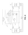
- FIG. 6 is a block diagram illustrating components of the apparatus in an alternative exemplary embodiment
- FIG. 7 is a block diagram illustrating components of a system in an exemplary embodiment.
- FIG. 8 is a block diagram illustrating components of a mobile computing device in an exemplary embodiment.
- FIG. 1 is a block diagram illustrating an exemplary embodiment of the inventive principles.
- an apparatus 100 is depicted that includes a first data and power interface 101 (for example, a mini-USB connector adapted to mate with a mini-USB port of a mobile computing device), a second data and power interface 102 (for example, a mini-USB port adapted to accept a mini-USB-compatible connector), and internally includes a wireless charging unit 110 and a control unit 120 .
- a first data and power interface 101 for example, a mini-USB connector adapted to mate with a mini-USB port of a mobile computing device
- a second data and power interface 102 for example, a mini-USB port adapted to accept a mini-USB-compatible connector
- internally includes a wireless charging unit 110 and a control unit 120 for example, a wireless charging unit 110 and a control unit 120 .
- the two data and power interfaces 101 and 102 are capable of transmitting power and/or data to and/or from a mobile computing device 150 that is joined with the apparatus 100 (i.e., when the first data and power interface 101 is connected to a data and power interface port 151 of the mobile computing device 150 ).
- the wireless charging unit 110 further includes a wireless power receiver 111 and a wireless charging integrated circuit (IC) 112 .
- the wireless charging unit 110 is a Qi-compatible magnetic induction-type wireless charging unit that includes an RX antenna coil as the wireless power receiver 111 and a Qi-compatible IC as the wireless charging IC 112 (for example, the Texas Instruments (TI) BQ51013 wireless charge IC).
- the control unit 120 includes circuitry connected to the first and second data and power interfaces 101 and 102 and to the wireless charging unit 110 that, together with the wireless charging unit 110 , facilitates switching the apparatus 100 between different modes of operation under different conditions.
- the control unit 120 includes few circuit components suitably connected to the other elements of the apparatus 100 .
- the control unit 120 includes a processor-based controller utilizing processor-executable instructions stored on a non-transitory processor-readable medium to switch the apparatus 100 between different modes of operation.
- FIG. 1 further depicts a mobile computing device 150 , which includes a data and power port 151 , adapted to be joined with the apparatus 100 in a manner such that the data and power port 151 mates with the first data and power interface 101 so as to establish a connection through which power and/or data may be transmitted to and/or from the mobile computing device 150 .
- the various mobile computing devices usable in connection with various embodiments of the invention may include, without limitation, mobile phones (including smartphones), tablets and “phablets,” laptop computers, headset accessories, drone aircrafts or other electronic vehicles, video game systems, television remotes, and microcontroller circuits (such as Raspberry Pi, BeagleBone, etc.).
- the mobile computing devices should be configured such that they are able both to provide and receive power and data via a data and power interface of the mobile computing devices (e.g., a USB OTG-enabled smartphone having a mini-USB port is able to provide power via the mini-USB port to an external device when a USB OTG-compatible cable/connector is present).
- a USB OTG-enabled smartphone having a mini-USB port is able to provide power via the mini-USB port to an external device when a USB OTG-compatible cable/connector is present.
- the apparatus 100 takes on different forms and dimensions corresponding to the different types of mobile computing devices.
- the apparatus 100 may have the shape of a smartphone case similar to the shape depicted in FIG. 1 , with a recessed space adapted to fit the mobile computing device 150 .
- the apparatus 100 may be a sleeve or a case with a cover, where the sleeve or case includes first and second data and power interfaces 101 and 102 .
- Examples of configurations of the apparatus 100 include, but are not limited to, cases, protective outer shells, sleeves, and standalone adapters or attachments.
- FIG. 2 is a block diagram illustrating different contexts of operation for a mobile computing device 150 connected to an apparatus 100 (as described above with respect to FIG. 1 ). Six different contexts of operation are illustrated with respect to FIG. 2 based on: (1) whether the combined apparatus 100 and mobile computing device 150 is in the presence of a wireless power source 200 (for example, as a Qi-compatible charging pad with a TX antenna coil); and (2) whether a load device 201 (for example, a keyboard or mouse, other accessory, or another mobile computing device) is connected to the second data and power interface 102 , a wired power source 202 (for example, an adapter plugged into a wall outlet or another computing device) is connected to the second data and power interface 102 , or nothing is connected to the second data and power interface 102 (represented by the box “no connection 203 ”).
- a wireless power source 200 for example, as a Qi-compatible charging pad with a TX antenna coil
- a load device 201 for example, a keyboard or mouse, other accessory
- control unit 120 and the wireless charging unit 110 of the apparatus 100 cause the apparatus 100 to behave as shown in the following table:
- Wireless power Load device Mobile computing device provides power to load source available connected device; wireless charging suspended Wired power Wired power source provides power to mobile source connected computing device; wireless charging suspended No connection Wireless power source provides power to mobile computing device.
- Wireless power Load device Mobile computing device provides power to load source unavailable connected device; wireless charging unavailable Wired power Wired power source provides power to mobile source connected computing device; wireless charging unavailable No connection No power transfer occurs.
- wirelessly charging the mobile computing device 150 via the apparatus 100 will not occur when an external source (whether a load device 201 or a wired power source 202 ) is connected to the second data and power interface 102 of the apparatus 100 , regardless of whether a wireless power source 200 is available to the apparatus 100 .
- This exemplary embodiment thus provides the user of the mobile computing device 150 and the apparatus 100 with a variety of functionality while the mobile computing device 150 is connected to the apparatus 100 .
- the first and second data and power interfaces 101 and 102 of the apparatus 100 allow the mobile computing device 150 to provide power to the load device 201 .
- the user may connect a peripheral device such as a mouse or keyboard to the second data and power interface 102 , and the peripheral device is provided with power from the mobile computing device 150 (e.g., from a battery of the mobile computing device 150 ) via the first and second data and power interfaces 101 and 102 of the apparatus 100 (as well as the data and power interface 151 of the mobile computing device 150 ).
- Data may also be provided to and/or from the mobile computing device from and/or to the load device 201 (e.g., data corresponding to keystrokes or movement associated with a peripheral device).
- a load device 201 is the connection of another mobile computing device to the mobile computing device 150 .
- a second smartphone which, for example, may be non-USB OTG-enabled or may be a USB OTG-enabled smartphone connected via a non-USB OTG-compatible USB connector or via the non-USB OTG-enabled end of a USB OTG-compatible USB connector
- the second data and power interface 102 which in this example is a mini-USB port via a USB cable that has male-type mini-USB connectors on both ends.
- the first USB OTG-enabled smartphone is able to provide power to the second smartphone, and may further be able to exchange data with the second smartphone.
- load devices 201 include, but are not limited to, a standalone memory drive, such as an external hard drive or a USB flash drive, or a memory reader adapted to read and/or write data from a memory card, which are connectable to the data and power interface 102 to provide power to the load device 201 and to communicate data to and/or from the mobile computing device 150 .
- a standalone memory drive such as an external hard drive or a USB flash drive
- a memory reader adapted to read and/or write data from a memory card which are connectable to the data and power interface 102 to provide power to the load device 201 and to communicate data to and/or from the mobile computing device 150 .
- the operation of the control unit 120 in combination with the wireless charging unit 110 is configured such that wireless charging of the mobile computing device 150 does not occur, even if the wireless power source 200 is available.
- the operation of the control unit 120 in combination with the wireless charging unit 110 also do not allow for wireless charging of the mobile computing device 150 regardless of whether the wireless power source 200 is available or not, as it is generally more efficient to provide wired charging relative to wireless charging.
- the wired power source 202 is a standalone battery or other type of energy storage device.
- the wired power source 202 is another mobile computing device, such as a laptop or desktop computer or a smartphone, that provides power to the apparatus 100 along a wired connection (e.g., an ordinary USB cable that is not USB OTG-compatible, or a USB OTG-compatible cable) that is plugged into the second data and power interface 102 .
- a wired connection e.g., an ordinary USB cable that is not USB OTG-compatible, or a USB OTG-compatible cable
- the operation of the control unit 120 and wireless charging unit 110 is configured to determine that power is being input to the apparatus 100 along the second data and power interface 102 and treats the connected device as a wired power source 202 . This results in wireless charging being suspended (even if a wireless power source 200 is available), and power flows from the wired power source 202 to the mobile computing device 150 .
- the operation of the control unit 120 and wireless charging unit 110 causes wireless charging to be provided to the mobile computing device 150 using a wireless power source 200 as the source for the power.
- a wireless power source 200 is unavailable, no power transfer occurs.
- a device connected to the second data and power interface 102 of the apparatus 100 is capable of being either a load device 201 or a wired power source 202 (for example, when the mobile computing device is a USB OTG-enabled smartphone and the external device is another USB OTG-enabled smartphone).
- the configuration of the cable connecting the two devices dictates which device acts as the load device 201 and which device acts as the wired power source 202 .
- one end of the USB-OTG-compatible cable has an ID pin grounded while the other end of the USB-OTG-compatible cable has the ID pin in a not connected (NC) state.
- the smartphone connected to the end with the ID pin grounded acts as a “host” device that provides power to the smartphone connected to the end with the ID pin in the NC state, which acts as the load device 201 .
- FIG. 3 is a flowchart illustrating a process flow for different modes of operation of the apparatus 100 .
- the apparatus 100 detects whether an external device is connected to the second data and power interface 102 and, if so, determines whether the external device is a load device or a wired power source (e.g., based on the absence/presence of power at the second data and power interface 102 and based on a mode of operation of the wireless charging unit 110 set by the control unit 120 ). If a load device is connected, the apparatus 100 provides power from the mobile computing device 150 to the load device (stage 305 ). If a wired power source is connected, the apparatus 100 provides power to the mobile computing device 150 from the wired power source (stage 306 ).
- the apparatus 100 If no external device is connected to the second data and power interface 102 (stage 301 ), the apparatus 100 provides wireless power to the mobile computing device 150 from a wireless power receiver of the apparatus at stage 303 (if wireless power is available (stage 302 )). If no external device is connected to the second data and power interface 102 (stage 301 ) and wireless power is unavailable (stage 302 ), no power transfer occurs with respect to the apparatus 100 until an external device is connected or wireless power becomes available.
- distinguishing between whether a connected external device is a load or a wired source at stage 304 is further based on the type of cable/connector used to connect the external device to the second data and power interface 102 .
- the cable and connector used to connect an external load device to the mini-USB port should be USB OTG-compatible in order for the apparatus 100 to recognize that the connected device needs to draw power from the mobile computing device 150 .
- An ID pin of a USB OTG-compatible cable/connector is grounded, which indicates to the apparatus that the cable/connector is USB OTG-compatible such that the apparatus 100 treats the connected external device is a load device that will draw power from the mobile computing device 150 via the second data and power interface 102 .
- FIG. 4 is a block diagram that further illustrates the relationship between components of the apparatus 100 .
- an external source i.e., a load device or a wired power source
- an ID path 402 provided between the first and second data and power interfaces 101 and 102 that is utilized by the control unit 120 allows the control unit 120 to provide an appropriate control signal to the wireless charging unit 110 via the control signal path 404 .
- the control unit 120 sends a control signal along the control signal path 404 to the wireless charging unit 110 based on a ground being connected to an ID pin of the second data and power interface 102 on the ID path 402 that puts the apparatus 100 in a state such that wireless charging and wired charging of the mobile computing device 150 are suspended/disabled, and such that the mobile computing device 150 provides power along power path 401 to the external device connected via the USB OTG-compatible USB connector/cable.
- the control unit 120 sends a different control signal to the wireless charging unit 110 based on the ID path 402 being in a not connected (N.C.) state (as opposed to being in a grounded state).
- the wireless charging unit (which is in an appropriate mode of operation based on a control signal from the control unit) suspends wireless charging and allows power to flow from the wired power source to the mobile computing device 150 via the non-USB OTG-compatible USB connector/cable and via the data and power interfaces 101 and 102 along the entirety of power path 401 .
- control unit 120 and the wireless charging unit 110 allow for wireless power to be provided to the mobile computing device 150 via the part of the power path 401 that connects the wireless charging unit 110 to the first data and power interface 101 , while no power is transmitted or received on the part of the power path 401 that connects the wireless charging unit 110 to the second data and power interface 102 .
- the wireless charging unit 110 is a Qi-type wireless charging unit that includes a TI BQ51013 IC as the wireless charging IC.
- This exemplary implementation of the invention using the TI BQ51013 IC further includes a dual P-channel MOSFET load switch, the MTM68411 loadswitch.
- Further details regarding the TI BQ51013 IC are described in Texas Instruments, “bq51010, bq51011, bq51013: Integrated Wireless Power Supply Receiver, Qi (Wireless Power Consortium) Compliant,” April 2011 (Revised August 2011), which is incorporated by reference herein it is entirety.
- Further details regarding the MTM68411 loadswitch are described in Panasonic, “MTM68411 Silicon P-channel MOS FET,” January 2012, which is incorporated by reference herein it is entirety.
- the TI BQ51013 includes two “Enable” pins, EN1 and EN2, which allows for four different modes of operation. Two of these four modes are used in exemplary embodiments of the invention, and these two modes are shown in the table below:
- 0 mode represents a “normal” mode of operation. If power is present at an adapter input “AD” of the wireless charging IC, the wireless charging IC control a switch of the wireless charging unit to allow a power output that from the wireless charging unit that uses the power provided at the adapter input as the power source (wired charging). If power is not present at the adapter input, wireless power from the wireless power receiver of the wireless charging unit is used as the power source and is output from the wireless charging unit (given that a wireless power source is available). 1 0 This 1
- wireless charging ICs such as wireless charging ICs manufactured by Toshiba, Panasonic, Rohm and IDT
- wireless charging ICs manufactured by Toshiba, Panasonic, Rohm and IDT provide similar input pins that correspond to different modes of operation for corresponding wireless charging units (or variations thereof), and that these other wireless charging ICs are also usable in connection with embodiments of the invention.
- Other types of loadswitches are usable in other embodiments as well.
- FIGS. 5A-5C depict components of this exemplary implementation of the invention in different modes of operation, given that a USB OTG-enabled mobile computing device 150 is connected to the first data and power interface 101 of the apparatus 100 .
- These figures depict the second data and power interface 102 as a female-type micro-B USB socket having five pins (Vcc, D ⁇ , D+, ID, and Ground) and the first data and power interface 101 as a male-type micro-B USB connector having the same five pins.
- the control unit 120 in this exemplary implementation includes an inverter IC with an output connected to the EN1 pin of the wireless charging IC (and with a pull-up resistor connected to the input).
- the EN2 pin of the wireless charging IC (not depicted) is held to low or “0” in all modes of operation with respect to this exemplary implementation. It will be appreciated that the wireless charging unit 110 further includes a wireless power receiver (which is not depicted in FIGS. 5A-5C for simplicity).
- FIG. 5A illustrates the apparatus 100 under conditions where a non-USB OTG-compatible USB connector/cable, corresponding to an external wired power source, is connected to the female-type micro-B USB socket.
- Power is provided via the Vcc pin of the female-type micro-B USB socket to the wireless charging unit 110 , and the power detected at the AD input of the wireless charging IC causes the AD-EN output to register high, allowing power to flow across the load switch from the female-type USB socket to the male-type USB connector (i.e., from the external wired power source to the mobile computing device 150 joined with the apparatus 100 ).
- the ID pin of the female-type micro-B USB socket is in a not connected (N.C.) state.
- the inverter IC of the control unit 120 receives a high input and outputs low, causing the EN1 input of the wireless charging IC to register low or “0.” This results in the wireless charging IC to be in a 0
- Data may also be communicated between the external wired power source and the mobile computing device 150 along the Data: D ⁇ and DATA: D+ lines between the female-type USB socket and the male-type USB connector of the apparatus 100 in appropriate circumstances (for example, where the external wired power source is another computing device).
- FIG. 5B illustrates the apparatus 100 under conditions where a USB OTG-compatible connector/cable, corresponding to an external load device, is connected to the female-type micro-B USB socket. Because the connector/cable is USB OTG-compatible, the ID pin of the female-type micro-B USB socket is in a grounded state. This grounded state is passed along via the ID path to the male-type micro-B USB connector, and the mobile computing device 150 connected thereto is able to determine based on the presence of a ground at the ID pin of the male-type micro-B USB connector that a USB OTG-compatible load device is connected. This causes 5V power to be output from the mobile computing device 150 via the power pin of the male-type micro-B USB connector of the apparatus 100 .
- the load switch allows power to flow from the male-type USB connector to the female-type USB socket (i.e., from the mobile computing device 150 to the external load device). Further, because power (and voltage) is present at the AD input of the wireless charging IC, wireless charging is suspended and the wireless charging output OUT of the wireless charging IC does not output wirelessly received power.
- Data may also be communicated between the external load device and the mobile computing device 150 along the Data: D ⁇ and DATA: D+ lines between the female-type USB socket and the male-type USB connector of the apparatus 100 .
- FIG. 5C illustrates the apparatus 100 under conditions where nothing is connected to the female-type micro-B USB socket.
- the USB_ID pin of the female-type micro-B USB socket is in a not connected (N.C.) state, and the AD input to the wireless charging IC is low because no power is being provided or received at the power pin of the female-type USB socket.
- FIGS. 5A-5C depict an exemplary implementation where the control unit 120 comprises an inverter IC and a pull-up resistors. It will be appreciated that other implementations of the control unit 120 are possible without departing from the inventive principles.
- FIG. 6 depicts an example of one such implementation where the control unit 120 includes a transistor and two pull-up resistors. The transistor-based implementation of the control unit 120 in FIG. 6 operates in the same way as discussed above with respect to FIGS. 5A-5C , providing a suitable output to the EN_1 input pin of the wireless charging IC such that the operation of the control unit 120 and the wireless charging unit 110 provide different modes of operation for the apparatus under different conditions.
- control unit 120 may be a processor-based controller utilizing processor-executable instructions stored on a non-transitory processor-readable medium to switch the apparatus between different modes of operation, wherein the controller has similar inputs from an ID pin of the second data and power interface 102 and the power pin from the first data and power interface 101 , and similar output to the wireless charging unit 110 .
- FIGS. 1-6 relate to systems in which the apparatus 100 providing different modes of operation is separate from the mobile computing device 150 .
- Other embodiments of the system include configurations where the control unit 120 and the wireless charging unit 110 are integrated in the mobile computing device 150 .
- a first data and power interface 101 may be omitted, and the second data and power interface 102 is conceptually substituted with the data and power interface 151 of the mobile computing device 150 itself.
- FIG. 7 is a block diagram illustrating these different arrangements.
- the system includes the first data and power interface 101 and the second data and power interface 102 , and the power path 401 , ID path 402 , and the data and ground paths 403 , extend through the first data and power interface 101 to appropriate connections in the mobile computing device 150 .
- the power path 401 connects to a device power unit 901 (such as the battery of a mobile computing device), and the ID path 402 and data and ground paths 403 connects to a device controller 902 (e.g., the processor-based control system of a mobile computing device).
- a device power unit 901 such as the battery of a mobile computing device
- the ID path 402 and data and ground paths 403 connects to a device controller 902 (e.g., the processor-based control system of a mobile computing device).
- the wireless charging unit 110 and control unit 120 are part of the mobile computing device 150 such that the power path 401 and ID path 402 connect from the data and power interface 151 of the mobile computing device 150 to a device power unit 901 and a device control unit 902 of the mobile computing device 150 .
- the wireless charging unit 110 and control unit 120 which are integrated in the mobile computing device 150 , provide for different modes of operation to the mobile computing device 150 in which: (1) the mobile computing device delivers power to an external load device; (2) the mobile computing device receives power from an external wired power source; and (3) the mobile computing device is wirelessly charged via the integrated wireless charging unit.
- These integrated embodiments utilize the data and power interface 151 of the mobile computing device 150 , and a separate apparatus having the first and second data and power interfaces 101 and 102 would not be needed.
- the mobile computing device 150 incorporates the wireless charging unit 110 and the control unit 120
- the mobile computing device 150 is further configured such that an “adapter detect” input of the device control unit 902 (e.g., a GPIO pin available on the mobile computing device's control unit) is connected to the loadswitch of the wireless charging unit 110 , as depicted in FIG. 8 , such that the mobile computing device 150 is able to set different charging rates for wireless charging versus wired charging.
- an “adapter detect” input of the device control unit 902 e.g., a GPIO pin available on the mobile computing device's control unit
- this configuration allows the device control 902 sets a charging rate that is appropriate for wired charging (e.g., 500 mA for charging using the USB 2.0 specification) by detecting that the AD-EN pin is low via a detection line 910 .
- a charging rate that is appropriate for wired charging (e.g., 500 mA for charging using the USB 2.0 specification) by detecting that the AD-EN pin is low via a detection line 910 .
- the device control 902 allows for a different charging rate that is appropriate for wireless charging (e.g., 1 A).
- the mobile computing device 150 will still act as a “host” device and provide power to a load device 201 connected via the USB OTG-compatible cable/connector, similar to the previous exemplary embodiments discussed above.
Landscapes
- Engineering & Computer Science (AREA)
- Computer Networks & Wireless Communication (AREA)
- Power Engineering (AREA)
- Charge And Discharge Circuits For Batteries Or The Like (AREA)
Priority Applications (3)
| Application Number | Priority Date | Filing Date | Title |
|---|---|---|---|
| US14/305,847 US9548622B2 (en) | 2014-06-16 | 2014-06-16 | Wirelessly charging a mobile device and utilizing the mobile device as a power source |
| TW103131724A TWI528674B (zh) | 2014-06-16 | 2014-09-15 | 無線充電裝置、系統以及方法 |
| CN201410519735.5A CN105226742B (zh) | 2014-06-16 | 2014-09-30 | 无线充电装置、系统以及方法 |
Applications Claiming Priority (1)
| Application Number | Priority Date | Filing Date | Title |
|---|---|---|---|
| US14/305,847 US9548622B2 (en) | 2014-06-16 | 2014-06-16 | Wirelessly charging a mobile device and utilizing the mobile device as a power source |
Publications (2)
| Publication Number | Publication Date |
|---|---|
| US20150364943A1 US20150364943A1 (en) | 2015-12-17 |
| US9548622B2 true US9548622B2 (en) | 2017-01-17 |
Family
ID=54836988
Family Applications (1)
| Application Number | Title | Priority Date | Filing Date |
|---|---|---|---|
| US14/305,847 Active 2035-02-03 US9548622B2 (en) | 2014-06-16 | 2014-06-16 | Wirelessly charging a mobile device and utilizing the mobile device as a power source |
Country Status (3)
| Country | Link |
|---|---|
| US (1) | US9548622B2 (zh) |
| CN (1) | CN105226742B (zh) |
| TW (1) | TWI528674B (zh) |
Cited By (1)
| Publication number | Priority date | Publication date | Assignee | Title |
|---|---|---|---|---|
| US9852098B2 (en) * | 2016-02-26 | 2017-12-26 | Essential Products, Inc. | Systems and techniques for intelligently switching between multiple sources of universal serial bus signals |
Families Citing this family (39)
| Publication number | Priority date | Publication date | Assignee | Title |
|---|---|---|---|---|
| US9037877B2 (en) | 2012-01-20 | 2015-05-19 | Dell Products L.P. | System and method for operating a plurality of components according to first or second operating characteristics in response to a detected first or second power input characteristic associated with a first or second power input respectively |
| CN203326671U (zh) * | 2013-07-10 | 2013-12-04 | 向智勇 | 一种用于电子烟盒的控制电路 |
| US10024679B2 (en) | 2014-01-14 | 2018-07-17 | Toyota Motor Engineering & Manufacturing North America, Inc. | Smart necklace with stereo vision and onboard processing |
| US9915545B2 (en) | 2014-01-14 | 2018-03-13 | Toyota Motor Engineering & Manufacturing North America, Inc. | Smart necklace with stereo vision and onboard processing |
| US10248856B2 (en) | 2014-01-14 | 2019-04-02 | Toyota Motor Engineering & Manufacturing North America, Inc. | Smart necklace with stereo vision and onboard processing |
| US10360907B2 (en) | 2014-01-14 | 2019-07-23 | Toyota Motor Engineering & Manufacturing North America, Inc. | Smart necklace with stereo vision and onboard processing |
| US9578307B2 (en) | 2014-01-14 | 2017-02-21 | Toyota Motor Engineering & Manufacturing North America, Inc. | Smart necklace with stereo vision and onboard processing |
| US9629774B2 (en) | 2014-01-14 | 2017-04-25 | Toyota Motor Engineering & Manufacturing North America, Inc. | Smart necklace with stereo vision and onboard processing |
| US10024667B2 (en) | 2014-08-01 | 2018-07-17 | Toyota Motor Engineering & Manufacturing North America, Inc. | Wearable earpiece for providing social and environmental awareness |
| US10024678B2 (en) | 2014-09-17 | 2018-07-17 | Toyota Motor Engineering & Manufacturing North America, Inc. | Wearable clip for providing social and environmental awareness |
| US9922236B2 (en) | 2014-09-17 | 2018-03-20 | Toyota Motor Engineering & Manufacturing North America, Inc. | Wearable eyeglasses for providing social and environmental awareness |
| USD768024S1 (en) | 2014-09-22 | 2016-10-04 | Toyota Motor Engineering & Manufacturing North America, Inc. | Necklace with a built in guidance device |
| US20160156387A1 (en) * | 2014-12-02 | 2016-06-02 | Sony Corporation | Method and system for wireless power and data transmission |
| US9576460B2 (en) | 2015-01-21 | 2017-02-21 | Toyota Motor Engineering & Manufacturing North America, Inc. | Wearable smart device for hazard detection and warning based on image and audio data |
| US10490102B2 (en) | 2015-02-10 | 2019-11-26 | Toyota Motor Engineering & Manufacturing North America, Inc. | System and method for braille assistance |
| US9586318B2 (en) * | 2015-02-27 | 2017-03-07 | Toyota Motor Engineering & Manufacturing North America, Inc. | Modular robot with smart device |
| US9811752B2 (en) | 2015-03-10 | 2017-11-07 | Toyota Motor Engineering & Manufacturing North America, Inc. | Wearable smart device and method for redundant object identification |
| US9677901B2 (en) | 2015-03-10 | 2017-06-13 | Toyota Motor Engineering & Manufacturing North America, Inc. | System and method for providing navigation instructions at optimal times |
| US9972216B2 (en) | 2015-03-20 | 2018-05-15 | Toyota Motor Engineering & Manufacturing North America, Inc. | System and method for storing and playback of information for blind users |
| US9734120B2 (en) * | 2015-07-14 | 2017-08-15 | Medtronic, Inc. | Methods, devices, and systems where an accessory controls power delivery from a host device to the accessory through an accessory port |
| US9898039B2 (en) | 2015-08-03 | 2018-02-20 | Toyota Motor Engineering & Manufacturing North America, Inc. | Modular smart necklace |
| US10024680B2 (en) | 2016-03-11 | 2018-07-17 | Toyota Motor Engineering & Manufacturing North America, Inc. | Step based guidance system |
| US9958275B2 (en) | 2016-05-31 | 2018-05-01 | Toyota Motor Engineering & Manufacturing North America, Inc. | System and method for wearable smart device communications |
| US10561519B2 (en) | 2016-07-20 | 2020-02-18 | Toyota Motor Engineering & Manufacturing North America, Inc. | Wearable computing device having a curved back to reduce pressure on vertebrae |
| KR20180018049A (ko) * | 2016-08-12 | 2018-02-21 | 엘지전자 주식회사 | 이동 단말기 |
| US10432851B2 (en) | 2016-10-28 | 2019-10-01 | Toyota Motor Engineering & Manufacturing North America, Inc. | Wearable computing device for detecting photography |
| US10012505B2 (en) | 2016-11-11 | 2018-07-03 | Toyota Motor Engineering & Manufacturing North America, Inc. | Wearable system for providing walking directions |
| US10521669B2 (en) | 2016-11-14 | 2019-12-31 | Toyota Motor Engineering & Manufacturing North America, Inc. | System and method for providing guidance or feedback to a user |
| CN108321858B (zh) * | 2017-01-16 | 2021-06-29 | 华硕电脑股份有限公司 | 充电保护装置及其方法 |
| US10172760B2 (en) | 2017-01-19 | 2019-01-08 | Jennifer Hendrix | Responsive route guidance and identification system |
| CN109388601B (zh) * | 2017-08-10 | 2023-07-18 | 成都圣成通幽科技有限公司 | 一种otg供电、充电自动切换模块的控制方法 |
| US11183864B2 (en) * | 2018-05-07 | 2021-11-23 | Apple Inc. | Multimode battery charging |
| CN111030200B (zh) * | 2018-10-10 | 2021-10-19 | 纬联电子科技(中山)有限公司 | 电子装置及其功率调整方法 |
| EP3723233A1 (en) * | 2018-10-15 | 2020-10-14 | Samsung Electronics Co., Ltd. | Electronic device and method for wired or wireless charging in electronic device |
| KR20200042426A (ko) * | 2018-10-15 | 2020-04-23 | 삼성전자주식회사 | 전자 장치 및 전자 장치에서 유무선 충전 방법 |
| TWI681604B (zh) * | 2018-11-16 | 2020-01-01 | 大陸商東莞寶德電子有限公司 | 可分離的充電板 |
| KR20200101225A (ko) * | 2019-02-19 | 2020-08-27 | 삼성전자주식회사 | 무선 전력 공유에 따른 사용자 인터페이스 제공 방법 및 장치 |
| CN111723034B (zh) * | 2019-03-19 | 2022-07-12 | 华为技术有限公司 | 一种外围设备 |
| DE102019118712A1 (de) * | 2019-07-10 | 2021-01-14 | Endress+Hauser Conducta Gmbh+Co. Kg | Feldgerät und Gegenstelle |
Citations (20)
| Publication number | Priority date | Publication date | Assignee | Title |
|---|---|---|---|---|
| KR20050000780A (ko) * | 2003-06-24 | 2005-01-06 | 주식회사 팬택앤큐리텔 | 휴대용 단말기의 유에스비 호스트/슬레이브 설정 장치 |
| US7791311B2 (en) * | 2005-10-24 | 2010-09-07 | Samsung Electronics Co., Ltd. | Apparatus and method of wirelessly sharing power by inductive method |
| US7889498B2 (en) * | 2008-11-17 | 2011-02-15 | Incase Designs Corp. | Portable electronic device case with battery |
| US7936147B2 (en) * | 2006-10-24 | 2011-05-03 | Hanrim Postech Co., Ltd. | Non-contact charger capable of wireless data and power transmission and related battery pack and mobile device |
| US20110199041A1 (en) * | 2010-02-17 | 2011-08-18 | Jerry Yang | Rechargeable battery product |
| CN102738869A (zh) | 2012-07-03 | 2012-10-17 | 东莞市中恒浩机电科技有限公司 | 无线充电式移动电源及充放电方法 |
| US8390255B1 (en) * | 2012-05-25 | 2013-03-05 | Incipio Technologies, Inc. | Battery case for mobile device |
| US20130175983A1 (en) * | 2006-01-31 | 2013-07-11 | Mojo Mobility, Inc. | Efficiency and flexibility in inductive charging |
| US20130278207A1 (en) * | 2012-04-20 | 2013-10-24 | Samsung Electronics Co. Ltd. | Wired/wireless charging apparatus and circuit |
| US20130285601A1 (en) * | 2012-04-30 | 2013-10-31 | Jamie Sookprasong | Alternating current direct current adapter with wireless charging |
| US20140203661A1 (en) * | 2013-01-21 | 2014-07-24 | Powermat Technologies, Ltd. | Inductive power receiver having dual mode connector for portable electrical devices |
| US20140285137A1 (en) * | 2013-03-20 | 2014-09-25 | Daniel J. SHAPLEY | Portable Power Transfer Device |
| US20140308995A1 (en) * | 2013-04-15 | 2014-10-16 | Che-Min Wu | Portable wireless charging apparatus and system |
| US20150015187A1 (en) * | 2013-07-10 | 2015-01-15 | Zhiyong Xiang | Control circuit and method for electronic cigarette box |
| US9077390B1 (en) * | 2013-12-18 | 2015-07-07 | Nxp B.V. | Wireless charging and communication |
| US20150194834A1 (en) * | 2014-01-06 | 2015-07-09 | Samsung Electronics Co., Ltd. | Charging method and charging apparatus for electronic device |
| US9123935B2 (en) * | 2008-01-18 | 2015-09-01 | Mophie, Inc. | Wireless communication accessory for a mobile device |
| US9197094B2 (en) * | 2013-03-07 | 2015-11-24 | Ford Global Technologies, Llc | Wireless charger and charging system with multi-compatibility |
| US9288295B2 (en) * | 2013-12-03 | 2016-03-15 | Vladimir Ivanovski | Modular mobile device case |
| US9318915B2 (en) * | 2013-03-20 | 2016-04-19 | Halo2Cloud Llc | Portable power charger with wireless and direct charging connectivity |
Family Cites Families (2)
| Publication number | Priority date | Publication date | Assignee | Title |
|---|---|---|---|---|
| CN103269114B (zh) * | 2013-05-24 | 2015-06-10 | 奇瑞汽车股份有限公司 | 一种双向充电装置和系统 |
| CN203339736U (zh) * | 2013-05-27 | 2013-12-11 | 七盟电子工业股份有限公司 | 行动电源的结构改良 |
-
2014
- 2014-06-16 US US14/305,847 patent/US9548622B2/en active Active
- 2014-09-15 TW TW103131724A patent/TWI528674B/zh active
- 2014-09-30 CN CN201410519735.5A patent/CN105226742B/zh active Active
Patent Citations (20)
| Publication number | Priority date | Publication date | Assignee | Title |
|---|---|---|---|---|
| KR20050000780A (ko) * | 2003-06-24 | 2005-01-06 | 주식회사 팬택앤큐리텔 | 휴대용 단말기의 유에스비 호스트/슬레이브 설정 장치 |
| US7791311B2 (en) * | 2005-10-24 | 2010-09-07 | Samsung Electronics Co., Ltd. | Apparatus and method of wirelessly sharing power by inductive method |
| US20130175983A1 (en) * | 2006-01-31 | 2013-07-11 | Mojo Mobility, Inc. | Efficiency and flexibility in inductive charging |
| US7936147B2 (en) * | 2006-10-24 | 2011-05-03 | Hanrim Postech Co., Ltd. | Non-contact charger capable of wireless data and power transmission and related battery pack and mobile device |
| US9123935B2 (en) * | 2008-01-18 | 2015-09-01 | Mophie, Inc. | Wireless communication accessory for a mobile device |
| US7889498B2 (en) * | 2008-11-17 | 2011-02-15 | Incase Designs Corp. | Portable electronic device case with battery |
| US20110199041A1 (en) * | 2010-02-17 | 2011-08-18 | Jerry Yang | Rechargeable battery product |
| US20130278207A1 (en) * | 2012-04-20 | 2013-10-24 | Samsung Electronics Co. Ltd. | Wired/wireless charging apparatus and circuit |
| US20130285601A1 (en) * | 2012-04-30 | 2013-10-31 | Jamie Sookprasong | Alternating current direct current adapter with wireless charging |
| US8390255B1 (en) * | 2012-05-25 | 2013-03-05 | Incipio Technologies, Inc. | Battery case for mobile device |
| CN102738869A (zh) | 2012-07-03 | 2012-10-17 | 东莞市中恒浩机电科技有限公司 | 无线充电式移动电源及充放电方法 |
| US20140203661A1 (en) * | 2013-01-21 | 2014-07-24 | Powermat Technologies, Ltd. | Inductive power receiver having dual mode connector for portable electrical devices |
| US9197094B2 (en) * | 2013-03-07 | 2015-11-24 | Ford Global Technologies, Llc | Wireless charger and charging system with multi-compatibility |
| US20140285137A1 (en) * | 2013-03-20 | 2014-09-25 | Daniel J. SHAPLEY | Portable Power Transfer Device |
| US9318915B2 (en) * | 2013-03-20 | 2016-04-19 | Halo2Cloud Llc | Portable power charger with wireless and direct charging connectivity |
| US20140308995A1 (en) * | 2013-04-15 | 2014-10-16 | Che-Min Wu | Portable wireless charging apparatus and system |
| US20150015187A1 (en) * | 2013-07-10 | 2015-01-15 | Zhiyong Xiang | Control circuit and method for electronic cigarette box |
| US9288295B2 (en) * | 2013-12-03 | 2016-03-15 | Vladimir Ivanovski | Modular mobile device case |
| US9077390B1 (en) * | 2013-12-18 | 2015-07-07 | Nxp B.V. | Wireless charging and communication |
| US20150194834A1 (en) * | 2014-01-06 | 2015-07-09 | Samsung Electronics Co., Ltd. | Charging method and charging apparatus for electronic device |
Non-Patent Citations (2)
| Title |
|---|
| Panasonic, MTM68411 Silicon P-channel MOS FET, 3 pages (Jan. 2012). |
| Texas Instruments, "Integrated Wireless Power Supply Receiver, Qi (Wireless Power Consortium) Compliant" 30 pages (2011). |
Cited By (2)
| Publication number | Priority date | Publication date | Assignee | Title |
|---|---|---|---|---|
| US9852098B2 (en) * | 2016-02-26 | 2017-12-26 | Essential Products, Inc. | Systems and techniques for intelligently switching between multiple sources of universal serial bus signals |
| US10353842B2 (en) | 2016-02-26 | 2019-07-16 | Essential Products, Inc. | Systems and techniques for intelligently switching between multiple sources of universal serial bus signals |
Also Published As
| Publication number | Publication date |
|---|---|
| CN105226742A (zh) | 2016-01-06 |
| TWI528674B (zh) | 2016-04-01 |
| TW201601409A (zh) | 2016-01-01 |
| US20150364943A1 (en) | 2015-12-17 |
| CN105226742B (zh) | 2018-10-23 |
Similar Documents
| Publication | Publication Date | Title |
|---|---|---|
| US9548622B2 (en) | Wirelessly charging a mobile device and utilizing the mobile device as a power source | |
| KR102468187B1 (ko) | 전자 장치 및 전자 장치의 외부 장치 충전 방법 | |
| JP6173297B2 (ja) | 携帯端末及びそのインターフェース方法 | |
| US9866055B2 (en) | Automatic scheme to detect multi-standard charger types | |
| CN106291210B (zh) | Usb接口检测器、检测方法、usb连接器及电子设备 | |
| US10241935B2 (en) | Portable device, cable assembly, and USB system | |
| US7886104B2 (en) | Detachable adapter and portable system | |
| JP5283719B2 (ja) | 電子機器及び電子機器システム | |
| US9772653B2 (en) | Mechanism for charging portable device with USB dock | |
| CN105518967B (zh) | 改变电流限制的装置和方法 | |
| US9330046B2 (en) | Portable instrument and docking station with divided universal serial bus communication device | |
| US9590441B2 (en) | Multi-standard compliant USB battery charging scheme with detection of host disconnection in ACA-DOCK mode | |
| CN111742459A (zh) | 用于根据在连接到外部电子装置的信号端处检测到的电压大小来控制输出到外部电子装置的电压的方法和电子装置 | |
| US20160372951A1 (en) | Dedicated USB Power Ports Coupled With A Multi-port USB Powered Hub | |
| KR102455442B1 (ko) | 전자 장치 및 전자 장치의 전원 공급 제어 방법 | |
| KR102091508B1 (ko) | 전자 장치의 전원 공급 회로 및 그 제어 방법 | |
| KR102348784B1 (ko) | 모드에 따라 신호 세기를 제어하는 전자 장치 및 방법 | |
| US20190324511A1 (en) | Controller, control method, and control program | |
| US9948094B1 (en) | Power level switching circuit for a dual port adapter | |
| US20120096286A1 (en) | Charging management method, charging control circuit and the host apparatus having the same | |
| CN107391410B (zh) | 桥接器 | |
| EP2642400A2 (en) | Processing device and processing system | |
| CN109845194A (zh) | 安全的外围设备通信 | |
| KR20200050260A (ko) | 외부 전자 장치로부터 전원을 공급받는 전자 장치 및 방법 | |
| US10193286B2 (en) | Electronic device and control method thereof |
Legal Events
| Date | Code | Title | Description |
|---|---|---|---|
| AS | Assignment |
Owner name: WISTRON CORPORATION, TAIWAN Free format text: ASSIGNMENT OF ASSIGNORS INTEREST;ASSIGNORS:VICK, RONALD;OBERHAUSER, THOMAS;REEL/FRAME:033112/0428 Effective date: 20140409 |
|
| STCF | Information on status: patent grant |
Free format text: PATENTED CASE |
|
| MAFP | Maintenance fee payment |
Free format text: PAYMENT OF MAINTENANCE FEE, 4TH YEAR, LARGE ENTITY (ORIGINAL EVENT CODE: M1551); ENTITY STATUS OF PATENT OWNER: LARGE ENTITY Year of fee payment: 4 |
|
| MAFP | Maintenance fee payment |
Free format text: PAYMENT OF MAINTENANCE FEE, 8TH YEAR, LARGE ENTITY (ORIGINAL EVENT CODE: M1552); ENTITY STATUS OF PATENT OWNER: LARGE ENTITY Year of fee payment: 8 |