US9546939B2 - Inspecting device and inspecting method - Google Patents
Inspecting device and inspecting method Download PDFInfo
- Publication number
- US9546939B2 US9546939B2 US14/441,556 US201314441556A US9546939B2 US 9546939 B2 US9546939 B2 US 9546939B2 US 201314441556 A US201314441556 A US 201314441556A US 9546939 B2 US9546939 B2 US 9546939B2
- Authority
- US
- United States
- Prior art keywords
- point
- force
- slope
- unit
- designated
- Prior art date
- Legal status (The legal status is an assumption and is not a legal conclusion. Google has not performed a legal analysis and makes no representation as to the accuracy of the status listed.)
- Expired - Fee Related, expires
Links
Images


Classifications
-
- G—PHYSICS
- G01—MEASURING; TESTING
- G01N—INVESTIGATING OR ANALYSING MATERIALS BY DETERMINING THEIR CHEMICAL OR PHYSICAL PROPERTIES
- G01N3/00—Investigating strength properties of solid materials by application of mechanical stress
- G01N3/08—Investigating strength properties of solid materials by application of mechanical stress by applying steady tensile or compressive forces
-
- G—PHYSICS
- G01—MEASURING; TESTING
- G01M—TESTING STATIC OR DYNAMIC BALANCE OF MACHINES OR STRUCTURES; TESTING OF STRUCTURES OR APPARATUS, NOT OTHERWISE PROVIDED FOR
- G01M5/00—Investigating the elasticity of structures, e.g. deflection of bridges or air-craft wings
- G01M5/0075—Investigating the elasticity of structures, e.g. deflection of bridges or air-craft wings by means of external apparatus, e.g. test benches or portable test systems
-
- G—PHYSICS
- G01—MEASURING; TESTING
- G01N—INVESTIGATING OR ANALYSING MATERIALS BY DETERMINING THEIR CHEMICAL OR PHYSICAL PROPERTIES
- G01N3/00—Investigating strength properties of solid materials by application of mechanical stress
-
- G—PHYSICS
- G01—MEASURING; TESTING
- G01N—INVESTIGATING OR ANALYSING MATERIALS BY DETERMINING THEIR CHEMICAL OR PHYSICAL PROPERTIES
- G01N33/00—Investigating or analysing materials by specific methods not covered by groups G01N1/00 - G01N31/00
- G01N33/0078—Testing material properties on manufactured objects
-
- H—ELECTRICITY
- H01—ELECTRIC ELEMENTS
- H01H—ELECTRIC SWITCHES; RELAYS; SELECTORS; EMERGENCY PROTECTIVE DEVICES
- H01H50/00—Details of electromagnetic relays
-
- G01N2033/0078—
-
- G—PHYSICS
- G01—MEASURING; TESTING
- G01N—INVESTIGATING OR ANALYSING MATERIALS BY DETERMINING THEIR CHEMICAL OR PHYSICAL PROPERTIES
- G01N2203/00—Investigating strength properties of solid materials by application of mechanical stress
- G01N2203/02—Details not specific for a particular testing method
- G01N2203/0202—Control of the test
- G01N2203/0208—Specific programs of loading, e.g. incremental loading or pre-loading
-
- G—PHYSICS
- G01—MEASURING; TESTING
- G01N—INVESTIGATING OR ANALYSING MATERIALS BY DETERMINING THEIR CHEMICAL OR PHYSICAL PROPERTIES
- G01N2203/00—Investigating strength properties of solid materials by application of mechanical stress
- G01N2203/02—Details not specific for a particular testing method
- G01N2203/026—Specifications of the specimen
- G01N2203/0288—Springs
-
- H—ELECTRICITY
- H01—ELECTRIC ELEMENTS
- H01H—ELECTRIC SWITCHES; RELAYS; SELECTORS; EMERGENCY PROTECTIVE DEVICES
- H01H50/00—Details of electromagnetic relays
- H01H50/54—Contact arrangements
Definitions
- the present invention relates to an inspecting device and an inspecting method for inspecting the characteristics of an elastic component that is in a state of being assembled to an assembled body.
- the elastic component refers to a component used as a generation source of a stress corresponding to the deformation.
- the elastic component includes, for example, a spring or rubber.
- Patent Literature 1 discloses a core support plate plug inspecting device that measures a spring constant of a spring, which is a functional component of a core support plate plug.
- the core support plate plug inspecting device activates an actuator in a state with the spring being mounted on the core support plate plug, thereby pushing a piston (a hand) having a load cell at the end against the spring.
- the core support plate plug inspecting device detects a loading applied to the piston by the load cell; and detects a travel distance of the piston by a displacement meter.
- the core support plate plug inspecting device then calculates a spring constant of the spring mounted on the plug on the basis of these detection values.
- Patent Literature 1 it is supposed that, as a work of detaching the spring and the plug is not required, a work for confirming the soundness of the core support plate plug can be easily performed.
- Patent Literature 2 discloses an inspection system that inspects a spring force and a spring constant in a state with a spring being assembled so as to be sandwiched between a pump body and a housing.
- the spring is assembled in a compressed state and is in a state of generating a spring force in an extending direction of the spring, among the directions of action of the spring.
- An externally threaded member is disposed at a predetermined position in the extending direction of the spring in the housing, and the most extending position of the spring in a range of movement of the pump body is restricted by the external thread member.
- a piston driven by an actuator presses against the pump body so as to push the spring in a direction in which the spring in the direction of action of the spring force is compressed.
- the inspection system then calculates the spring constant on the basis of a loading generated by a pressing force and a measurement value of an end position of the pump body.
- the inspection system then obtains the spring force in an actual usage state on the basis of force information at a point where the external thread member is separated from the pump body (that is, a point where the force of the spring applied to the housing (a housing reaction force) becomes zero).
- Patent Literature 2 it is supposed that whether the actual spring force after assembly is within a set range can be determined.
- Patent Literature 1 Japanese Patent Application Laid-open No. S61-080091
- Patent Literature 2 Japanese Patent Application Laid-open No. 2001-255238
- a deformation start point and a deformation end point of the elastic component are not always unchanged due to a positioning error of the workpiece and a dimension error of other components disposed around the elastic component. Therefore, the deformation start point and the deformation end point of the elastic component need to be designated for every inspecting operation.
- information of the deformation section of components other than the spring may be included in the set deformation section, and thus correct calculation results of the spring constant may not be obtained.
- information of a period, during which the piston is brought into contact with the shaft is cut out from the information of the travel distance of the piston. Therefore, it is required to designate a point where the piston comes into contact with the shaft for each inspecting operation, thereby causing problems of low productivity and high production costs.
- the objective of the technique described in Patent Literature 1 is to confirm the soundness of a core support plate plug.
- the object is to confirm whether the reaction force of a spring can endure a pressure difference between a lower part and an upper part of the core support plate plug in order to prevent the occurrence of any functional problem of the plug during the operation of a nuclear reactor.
- the compression amount of the spring changes. Therefore, even if it is found that the spring constant of the spring is the same, there are variations in the reaction force in the spring. As a result, a problem remains in which the robustness of the core support plate plug cannot be ensured.
- the present invention has been achieved in view of the above problems, and an objective of the present invention is to provide an inspecting device and an inspecting method for specifying a deformation start point or a deformation end point of an elastic component as easily as possible in a force waveform concerning an assembled body assembled thereto with the elastic component.
- the present invention relates to an inspecting device that includes: a force-waveform detection system that applies a load to an assembled body having an elastic component assembled thereto in a direction of action of the elastic component and acquires a force waveform describing a relation between the load and an amount of displacement; a reception unit that receives an input of a designated point during a process of deformation of the elastic component in the force waveform acquired by the force-waveform detection system; and an inspection unit that calculates a local slope of the force waveform at the designated point, calculates a local slope at a focus point different from the designated point, and determines, on the basis of a comparison between the local slope at the focus point and the local slope at the designated point, whether the focus point is a change point of the force waveform.
- the inspection unit searches for a first focus point that first satisfies, on the basis of the local slope at the designated point and a first parameter, a first condition at least stating that the local slope at the first focus point reaches a first threshold, while moving the first focus point in a direction away from the designated point by using the designated point as a point of the starting, specifies the first focus point first satisfying the first condition as a first change point, searches for a second focus point that first satisfies, on the basis of a second parameter, a second condition at least stating that the local slope at the second focus point reaches the local slope at the designated point or is inside of a range between the local slope at the designated point and the slope, while moving the second focus point in a direction approaching the designated point by using the first change point as a point of the starting, and specifies the second focus point first satisfying the second condition as a second change point.
- the inspecting device can specify a change point only by inputting a designated point, and thus the inspecting device can specify a deformation start point or a deformation end point of an elastic component as easily as possible.
- FIG. 1 is a diagram illustrating a configuration of an inspecting device according to a first embodiment of the present invention.
- FIG. 2 is a diagram illustrating a configuration of a robot.
- FIG. 3 is a diagram illustrating a mechanism of an electromagnetic contactor as an example of an inspection object.
- FIG. 4 is a diagram illustrating a mechanism of an electromagnetic contactor when a voltage is applied to a magnetizing coil.
- FIG. 5 is a diagram illustrating a mechanism of the electromagnetic contactor when a voltage is applied to the magnetizing coil.
- FIG. 6 is a diagram illustrating an operation of the robot.
- FIG. 7 is a diagram illustrating an operation of the robot.
- FIG. 8 is a diagram illustrating an operation of the robot.
- FIG. 9 is a diagram illustrating an operation of the robot.
- FIG. 10 is a diagram illustrating an operation of the robot.
- FIG. 11 is a diagram illustrating an example of a force waveform.
- FIG. 12 is a diagram illustrating a partial waveform.
- FIG. 13 is a flowchart illustrating an outline of an inspecting operation.
- FIG. 14 is a diagram illustrating various values related to the inspecting operation.
- FIG. 15 is a diagram illustrating a process at Step S 11 .
- FIG. 16 is a diagram illustrating a process at Step S 12 in the first embodiment.
- FIG. 17 is a flowchart illustrating a detailed operation of the process at Step S 12 in the first embodiment.
- FIG. 18 is a diagram illustrating a process at Step S 13 .
- FIG. 19 is a flowchart illustrating a detailed operation of the process at Step S 13 .
- FIG. 20 is a diagram illustrating a process at Step S 12 in a second embodiment.
- FIG. 21 is a flowchart illustrating a detailed operation of the process at Step S 12 in the second embodiment.
- FIG. 22 is a diagram illustrating an example of a force waveform.
- FIG. 1 is a diagram illustrating a configuration of an inspecting device according to a first embodiment of the present invention.
- An inspecting device 100 includes a robot 2 ; a force acquisition unit 3 ; a position acquisition unit 5 ; an acquired-condition designation unit 6 ; an inspection-unit number selection unit 7 ; an inspection-parameter designation unit 9 ; an inspection-range designation unit 10 ; a cutout unit 11 ; an inspection unit 8 ; an inspection output unit 12 ; and a display unit 13 .
- the robot 2 , the force acquisition unit 3 , and the position acquisition unit 5 function as a system for detecting the force-waveform in cooperation with each other.
- This force-waveform detection system can apply a load to an assembled body having an elastic component assembled thereto in a direction of action of the elastic component so as to acquire an aggregation of a pair of the load and an amount of displacement (hereinafter, the aggregation is referred to as “force waveform”).
- FIG. 2 is a diagram illustrating a configuration of the robot 2 .
- the robot 2 is a vertical articulated robot having a motor 2 a in a plurality of joints.
- the robot 2 includes a hand 4 near an end (at an end) via a force sensor 3 a .
- the force sensor 3 a can measure: force acting on each of a plurality of shafts each of which ends of the hand of the robot 2 is set as an origin; and a moment around the respective shafts. That is, the force sensor 3 a can measure the force and moment acting on the hand 4 .
- the hand 4 can be always provided at the end of the robot 2 .
- the robot 2 can be configured such that the robot 2 includes an opening/closing hand or a tool changer on the body side than the hand 4 of the robot 2 , so that the hand 4 is held by the opening/closing hand or the hand 4 is fitted to the tool changer only during the inspecting operation.
- the robot 2 can be such that it only performs an inspecting operation, or that it performs an inspecting operation during other operations such as transferring and assembling.
- the robot 2 instead of being a vertical articulated robot, can be such that it is a scalar robot or an orthogonal robot in which all the shafts are configured by a direct drive shaft (a shaft operating in a straight line).
- the inspecting device 100 drives the robot 2 ; pushes the hand 4 against the assembled body having the elastic component assembled thereto in a direction of deformation of the elastic component so as to apply a load; and measures the load and the amount of displacement in a pair, thereby being able to specify data at a deformation start point and a deformation end point of the elastic component in the force waveform.
- the force acquisition unit 3 acquires a force acting on the hand 4 from the force sensor 3 a .
- the force acquisition unit 3 sends the acquired force as a force detection value to the inspection unit 8 and the display unit 13 via the robot 2 and the cutout unit 11 .
- the force detection value includes a force in three-axis directions and moments about the respective axes.
- the force detection value includes a force in three-axis directions and a moment that can be measured among the moments about the axes.
- the force sensor 3 a is provided, for example, for each axis and for each moment in the force acquisition unit 3 ; and the respective force sensor 3 a sends the force detection value respectively to the inspection unit 8 and the display unit 13 .
- the position acquisition unit 5 acquires the end position of the hand 4 .
- the position acquisition unit 5 is configured to include a position sensor 5 a that measures the position of the motor 2 a .
- the position sensor 5 a corresponds to, for example, an encoder or a resolver.
- the position acquisition unit 5 detects the position of the motor 2 a by using the position sensor 5 a ; and acquires coordinate transformation of the detected position of the motor 2 a so as to calculates the end position of the robot 2 (the end position of the hand 4 ).
- the position acquisition unit 5 sends the acquired position to the inspection unit 8 and the display unit 13 via the robot 2 and the cutout unit 11 , as the acquired position being the position detection value.
- the acquired-condition designation unit 6 specifies a sampling period, the detection start point, and the detection end point regarding the force and position used by the force acquisition unit 3 and the position acquisition unit 5 .
- the acquired-condition designation unit 6 executes designation on the basis of, for example, a command included in a robot program describing the operation of the robot 2 .
- the acquired-condition designation unit 6 executes designation on the basis of the following command.
- FsTCond On is a robot language (a command) for designating the detection start point
- “1” is a number designating the sampling period. For example, when the number is “1”, the sampling period is 1.0 millisecond.
- the acquired-condition designation unit 6 executes designation on the basis of the following command.
- “FaTest On” is a robot language (a command) for designating the detection start point, by using the percentage to a travel distance from the operation start point to the operation end point of the hand 4 ; and “30” means that a point of 30% from the start point of an assembly operation is designated as the detection start point.
- the acquired-condition designation unit 6 executes designation on the basis of the following command.
- FsTest Off is a robot language (a command) for designating the detection end point, by using the percentage to the travel distance from the operation start point to the operation end point of the hand 4 ; and “50” means that a point of 50% from the start point of the assembly operation is designated as the detection end point.
- the percentage of the travel distance from the operation start point is used to designate the detection start point and the detection end point.
- the designation method is not limited thereto. The following, for example, can be used as the designation method: the percentage of the travel distance to the operation end point, the travel distance from the operation start point, the travel distance to the operation end point, or an elapsed time from operation start.
- the inspection-unit number selection unit 7 specifies an axis to be inspected, and selects an inspection unit number according to the type of operation to be performed by the robot 2 .
- the inspection unit number includes the number of designating the inspecting operation to be performed by the inspection unit 8 .
- the inspection-unit number selection unit 7 also sends information of the axis to be inspected to the designated inspection unit 8 , and sends the inspection unit number to the inspection-parameter designation unit 9 .
- the inspection-unit number selection unit 7 specifies the axis to be inspected and selects the inspection unit number on the basis of the robot program or an input by an operator.
- the inspection-unit number selection unit 7 selects “51” as the inspection unit number.
- the inspection-unit number selection unit 7 selects “52” as the inspection unit number.
- the inspection-unit number selection unit 7 performs selection of the inspection unit number and designation of the shaft by executing the following command in the robot program.
- FsTAlgo is a robot language (a command) for designating the inspection unit number and the shaft
- 52 indicates the inspection unit number
- 3 means that a Z-axis is designated as the axis to be inspected.
- the inspection-parameter specification unit (reception unit) 9 receives the inspection unit number from the inspection-unit number selection unit 7 .
- a storage unit 1 stores therein in advance a combination of the inspection parameters for each of the inspection unit number.
- the value of the inspection parameter is set in advance by, for example, an operator.
- the inspection-parameter designation unit 9 refers to the storage unit 1 in order to acquire the combination of the inspection parameters corresponding to the inspection unit number received from the inspection-unit number selection unit 7 .
- the inspection-parameter designation unit 9 sends (sets) the acquired combination of the inspection parameters to the inspection unit 8 . Details of the inspection parameter are described later.
- the inspection-parameter designation unit 9 acquires the inspection parameter corresponding to the inspection unit number and sets the inspection parameter.
- the present embodiment can be configured such that the combination of the inspection parameters is directly described in the robot program to be set.
- the inspection-range designation unit 10 designates a range to be sent to the inspection unit 8 out of pairs of force/position detection values acquired for the section from the detection start point to the detection end point. That is, the inspection-range designation unit 10 designates an inspection range for specifying a physical characteristic change point (a change point) in the force waveform.
- the physical characteristic change point refers to a point at which the slope changes in the force waveform.
- the deformation start point and the deformation end point both correspond to the physical characteristic change point. For example, when the inspection unit 8 is to measure the modulus of elasticity of the elastic component or force that is generated in a state with the elastic component being assembled, the deformation start point and the deformation end point need to be specified.
- the inspection-range designation unit 10 designates a section that has a sufficient range for specifying the deformation start point and the deformation end point, which includes all the sections from the deformation start point to the deformation end point of the elastic component. It is assumed, here, that a start point of the range designated by the inspection-range designation unit 10 is an inspection-process start point; and an end point thereof is an inspection-process end point. The inspection-process start point and the inspection-process end point are sent to the cutout unit 11 .
- the inspection-process start point and the inspection-process end point can be designated by an orthogonal coordinate position of the robot 2 .
- the inspection-process start point and the inspection-process end point are designated by the percentage to a total travel distance, assuming that the total travel distance (obtained by accumulating an absolute value of the travel distance between pieces of position data on the designated axis) from the starting of the detected force waveform (the detection start point) to the ending (the detection end point) is 100%.
- the starting of the position data of the axis to be inspected is 0% and the ending thereof is 100%.
- the inspection-process start point and the inspection-process end point can be designated on the basis of the following command described in the robot program.
- FsTBat is a robot language (a command) for designating the inspection-process start point and the inspection-process end point by the ratio to the total travel distance; and “70, 100” means that a position of 70% is designated as the inspection-process start point and a position of 100% is designated as the inspection-process end point.
- the cutout unit 11 cuts out a waveform in the range designated by the inspection-range designation unit 10 out of the force waveform detected by the force acquisition unit 3 and the position acquisition unit 5 and sends the cut out waveform to the inspection unit 8 . Because the cutout unit 11 excludes information needless to measure the characteristics from the detected force waveform, the time required for the inspection process can be reduced.
- the inspection unit 8 measures the characteristics of the elastic component on the basis of the force waveform cut out by the cutout unit 11 and the inspection parameter designated by the inspection-parameter designation unit 9 .
- the axis to be inspected by the inspection unit 8 is designated by the inspection-unit number selection unit 7 . Further, the inspecting operation to be performed by the inspection unit 8 is different for each inspection unit number. For example, the inspecting operation for calculating the modulus of elasticity (a spring constant when the elastic component is a spring) as the characteristics is described later.
- the inspection unit 8 includes a reference-characteristics calculation unit 81 , a characteristic-change-point recognition unit 82 , and a characteristics calculation unit 83 .
- the reference-characteristics calculation unit 81 calculates reference characteristics (described later) from the cut out force waveform.
- the characteristic-change-point recognition unit 82 specifies a physical characteristic change point on the basis of the calculated reference characteristics, and specifies a section between two physical characteristic change points. Hereinafter, the section between two physical characteristic change points may be referred to as “characteristic section”.
- the characteristics calculation unit 83 calculates the characteristics on the basis of the force waveform of the characteristic section.
- the characteristics calculation unit 83 sends the calculated characteristics to the inspection output unit 12 and the display unit 13 .
- the characteristics calculation unit 83 can send the characteristic section or the physical characteristic change point together with the characteristics to the inspection output unit 12 and the display unit 13 .
- the inspection output unit 12 can notify the information sent from the inspection unit 8 to an external control device via I/O or the like.
- the external control device can use the notified information to execute production control. Specifically, the external control device confirms whether the modulus of elasticity of the elastic component is within a rated range, and if the modulus of elasticity is not within the rated range, the external control device can determine that the product is defective.
- the external control device can confirm whether the assembly work is successfully done by comparing force detection values at a point of the start and at an end point of the characteristic section or the position detection value, or both values with the force detection values at the point of the start and the end point or the position detection value, or both values when the assembly work has been normally complete.
- the display unit 13 is a display such as an LCD.
- the display unit 13 can be a programmable display device that processes input information according to a predetermined program and displays the processed information.
- the display unit 13 displays the force waveform detected by the force acquisition unit 3 and the position acquisition unit 5 in a graph, or displays the information that is input from the inspection unit 8 .
- any of or all of the storage unit 1 , the inspection-unit number selection unit 7 , the inspection-parameter designation unit 9 , the inspection-range designation unit 10 , the cutout unit 11 , the inspection unit 8 , the inspection output unit 12 , and the display unit 13 can be realized by a computer having a storage device, an arithmetic device, an input device, and a display device.
- the storage device is configured by a ROM or a RAM, or a combination thereof, and stores therein the inspection program in advance.
- the storage device functions as the storage unit 1 .
- the arithmetic device functions as any of or all of the storage unit 1 , the inspection-unit number selection unit 7 , the inspection-parameter designation unit 9 , the inspection-range designation unit 10 , the cutout unit 11 , the inspection unit 8 , and the inspection output unit 12 , by executing the inspection program stored in the storage device.
- the input device is, for example, a mouse and a keyboard, and sends input information from an operator to the arithmetic device.
- the display device is, for example, a display such as an LCD, and functions as the display unit 13 .
- the computer can be incorporated in a robot controller that controls the robot 2 .
- FIG. 3 is a diagram illustrating a mechanism of an electromagnetic contactor as an example of the inspection object.
- An electromagnetic contactor 200 includes a housing upper part 14 , a movable contact point 15 , a fixed contact point 16 , a movable iron core 17 , a plate 18 , a magnetizing coil 19 , a fixed iron core 20 , a housing lower part 21 , a push bar 22 , a contact spring 23 , a movable contact 24 , and a tripping spring 25 .
- the movable iron core 17 includes a movable iron-core central part 17 a .
- the push bar 22 includes a window 22 a .
- FIG. 3 illustrates a mechanism of the electromagnetic contactor 200 in a state where the magnetizing coil 19 is not magnetized.
- the housing upper part 14 and the housing lower part 21 are fixed by a fixing component (for example, a screw).
- the magnetizing coil 19 is disposed inside of the housing lower part 21 .
- the magnetizing coil 19 is held inside of the fixed iron core 20 .
- the plate 18 is attached to an upper part of the magnetizing coil 19 .
- the movable iron core 17 is disposed so as to face the fixed iron core 20 with a predetermined gap from the fixed iron core 20 .
- the tripping spring 25 is provided between the fixed iron core 20 and the movable iron core 17 .
- the tripping spring 25 is disposed so as to be wound around the movable iron-core central part 17 a .
- the tripping spring 25 is sandwiched between the plate 18 and the movable iron core 17 .
- the tripping spring 25 is in a compressed state at any time so as to generate a force in an extending direction.
- the push bar 22 is provided on an upper part of the movable iron core 17 .
- the push bar 22 and the movable iron core 17 are fixed together.
- the push bar 22 and the movable iron core 17 are guided by the housing upper part 14 and the housing lower part 21 so as to be able to slide in a vertical direction integrally.
- a hole is bored in the housing upper part 14 , and the hand 4 is inserted from the hole, thereby enabling the push bar 22 to move downward (that is, in a direction further compressing the tripping spring 25 ).
- the window 22 a is provided in the middle of the push bar 22 .
- the movable contact 24 is held in the window 22 a .
- the movable contact 24 is biased downward by the contact spring 23 formed of a compression coil spring so as to be able to slide along the window 22 a .
- the movable contact point 15 is attached respectively to the opposite ends of the movable contact 24 . Further, the movable contact point 15 is disposed so as to face the fixed contact point 16 with a predetermined gap therebetween.
- the fixed contact point 16 is attached to a part of the housing upper part 14 .
- FIGS. 4 and 5 are explanatory diagrams of a mechanism of the electromagnetic contactor 200 when a voltage is applied to the magnetizing coil 19 .
- a voltage is applied to the magnetizing coil 19
- electric current flows to the magnetizing coil 19 ; and the magnetizing coil 19 generates magnetic flux.
- a force of attraction due to the magnetic flux generated by the magnetizing coil 19 is generated between the fixed iron core 20 and the movable iron core 17 .
- the force of attraction exceeds the biasing force by the tripping spring 25 , the movable iron core 17 and the push bar 22 move downward so as to compress the tripping spring 25 .
- FIG. 4 is a diagram illustrating a mechanism of the electromagnetic contactor 200 in a state at the moment when the movable contact point 15 and the fixed contact point 16 come into contact with each other.
- FIG. 5 is a diagram illustrating a mechanism of the electromagnetic contactor 200 in a state where a stronger voltage is further applied to the movable contact point 15 and the fixed contact point 16 being into contact with each other.
- the gap between the movable iron core 17 and the fixed iron core 20 is set to be larger than the gap between the movable contact point 15 and the fixed contact point 16 . Therefore, if a stronger voltage is applied in a state where the movable contact point 15 and the fixed contact point 16 are brought into contact with each other, the push bar 22 moves further downward in the state where the movable contact point 15 and the fixed contact point 16 being into contact with each other. With this configuration, compression of the contact spring 23 is started, and the tripping spring 25 is further compressed. The biasing force of the contact spring 23 to the movable contact 24 becomes contact pressure between the movable contact point 15 and the fixed contact point 16 .
- the contact pressure between the movable contact point 15 and the fixed contact point 16 needs to be maintained properly. If the contact force is not sufficient when the movable contact point 15 and the fixed contact point 16 make contact with each other, the contact state between the movable contact point 15 and the fixed contact point 16 becomes unstable. The unstable contact state causes loose connection. On the other hand, if the contact force is too high when the movable contact point 15 makes contact with the fixed contact point 16 , the movable contact point 15 or the fixed contact point 16 causes deformation due to the pressure, thereby reducing the service life of the movable contact point 15 or the fixed contact point 16 .
- the force of attraction needs to be controlled between the movable contact point 15 and the fixed contact point 16 due to the voltage applied to the magnetizing coil 19 and the spring force of the tripping spring 25 .
- FIGS. 6 to 10 are explanatory diagrams of an operation of the robot 2 .
- the robot 2 is driven under the control of the robot program.
- the robot 2 pushes down the push bar 22 of the electromagnetic contactor 200 by using the end of the hand 4 . That is, the robot 2 pushes the push bar 22 in a compression direction of the tripping spring 25 , among the directions of action of the tripping spring 25 .
- FIG. 7 is a diagram illustrating a position relation between the hand 4 and the electromagnetic contactor 200 in a state immediately before the inspecting operation (a state 1 ).
- FIG. 8 is a diagram illustrating the position relation between the hand 4 and the electromagnetic contactor 200 in a state when the contact just occurs between the hand 4 and the push bar 22 (a state 2 ).
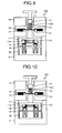
- FIG. 9 is a diagram illustrating the position relation between the hand 4 and the electromagnetic contactor 200 at the moment of contact between the movable contact point 15 and the fixed contact point 16 (a state 3 ).
- FIG. 10 is a diagram illustrating the position relation between the hand 4 and the electromagnetic contactor 200 in a state where the inspecting operation is finished (a state 4 ).
- FIG. 11 is a diagram illustrating an example of a force waveform acquired by the force acquisition unit 3 and the position acquisition unit 5 , when operations are sequentially performed from the state of the position relation between the hand 4 and the electromagnetic contactor 200 illustrated in FIG. 7 to the state thereof illustrated in FIG. 10 .
- a force detection value F (the unit is N) is plotted on a horizontal axis and a position detection value S (the unit is millimeters) is plotted on a vertical axis, in the force waveform.
- a section from point A to point B corresponds to a state before the hand 4 comes into contact with the push bar 22 (that is, the state 1 ).
- the point B corresponds to the state 2 .
- a section front point C to point D corresponds to a state before the movable contact point 15 and the fixed contact point 16 come into contact with each other, and corresponds to a compressed state of the tripping spring 25 .
- the point D corresponds to the state 3 .
- a section from point E to point F corresponds to a state after the movable contact point 15 and the fixed contact point 16 come into contact with each other; and a state where the contact spring 23 and the tripping spring 25 are simultaneously compressed.
- the point F corresponds to the state 4 .
- a difference FCB between the force detection value at the point B and the force detection value at the point C corresponds to the force generated by the tripping spring 25 (the biasing force of the tripping spring 25 ), when a voltage is not applied to the magnetizing coil 19 .
- a difference FED between the force detection value at the point D and the force detection value at the point E corresponds to the force generated by the contact spring 23 (the biasing force by the contact spring 23 ), when a voltage is not applied to the magnetizing coil 19 .
- the point C and the point D need to be specified in order to acquire the spring constant of the tripping spring 25 .
- the point B and the point C also need to be specified in order to acquire the biasing force of the tripping spring 25 .
- measurement noise components are added both to the detection values by the force acquisition unit 3 and the position acquisition unit 5 , the force waveform becomes a sawtooth waveform.
- An operation is described next in which the inspecting device 100 calculates characteristics. An operation is described here to detect a characteristic that is the spring force of the tripping spring 25 in the electromagnetic contactor 200 .
- An operation in which the robot 2 moves a hand from the state 1 to the state 4 is performed on the basis of the robot program.
- the inspecting device 100 acquires the force waveform from the detection start point to the detection end point set by the acquired-condition designation unit 6 .
- the cutout unit 11 cuts out a force waveform in a range designated by the inspection-range designation unit 10 (hereinafter, “partial waveform”) from the acquired force waveform and sends the cut out partial waveform to the inspection unit 8 .
- FIG. 12 is a diagram illustrating a partial waveform.
- the force detection value F is plotted on a horizontal axis; and the ratio of a travel distance, which is compared with the total travel distance from the detection start point to the detection end point assumed to be 100% (hereinafter, the percentage is referred to as “travel distance percentage”), is plotted on a vertical axis respectively in a graph of FIG. 12 .
- a pair of the force detection value F and the position detection value S detected by the force acquisition unit 3 and the position acquisition unit 5 is discrete data collected in the set sampling period.
- the travel distance percentage related to the i-th data is calculated according to the following mathematical expression 1.
- the force waveform in a range from Per1 to Per2 is cut out as the partial waveform (the partial waveform 26 ).
- the inspection-unit number selection unit 7 selects an inspection unit number “53” indicating an inspecting operation of calculating the spring force.
- the inspection unit 8 performs the inspecting operation corresponding to the inspection unit number “53”.
- FIG. 13 is a flowchart illustrating an outline of an inspecting operation performed by the inspection unit 8 ; and FIG. 14 is a diagram illustrating various values related to the inspecting operation by the inspection unit 8 .
- a horizontal axis indicates the force detection value F
- a vertical axis indicates a travel distance percentage.
- a section from a point L to a point R is a characteristic section (a characteristic section LR) of the tripping spring 25 .
- the point L is a physical characteristic change point at a point of starting of the characteristic section LR
- the point R is a physical characteristic change point at the end of the characteristic section LR.
- the point L corresponds to a deformation start point of the tripping spring 25 (that is, a point that the movable iron core 17 is just separated from the housing upper part 14 ); and the point R corresponds to a point where the state 3 has been reached (a deformation end point of the tripping spring 25 alone, that is, a point before the tripping spring 25 is compressed together with the contact spring 23 ).
- a point PM is an intermediate point of the characteristic section LR, and is an inspection parameter that can be set when the inspection unit number “53” is selected. In other words, the point PM is an arbitrary designated point of the force waveform in the process of deformation of the elastic component.
- a rough position in the middle of the force detection value from the deformation start point to the deformation end point of the tripping spring 25 , which is the elastic component to be inspected, can be set by using a travel distance percentage.
- a point SL is an adjacent point to the point L
- a point SR is an adjacent point to the point R.
- the point SL is a point having a smaller travel distance than the point L
- the point SR is a point having a larger travel distance than the point R.
- the reference-characteristics calculation unit 81 first acquires the pair of the force detection value F and the position detection value S in the inspection range constituting the partial waveform 26 in association with the data number (Step S 10 ). The reference-characteristics calculation unit 81 then calculates a slope (km) at the point PM (Step S 11 ). The reference-characteristics calculation unit 81 sends the calculated slope km as a reference characteristic (hereinafter, also “reference slope”) to the characteristic-change-point recognition unit 82 .
- a reference characteristic hereinafter, also “reference slope”
- the characteristic-change-point recognition unit 82 specifies the point SL as a rough change point (Step S 12 ); and specifies the point L based the specified point SL (Step S 13 ).
- the characteristic-change-point recognition unit 82 then specifies the point SR as a rough change point (Step S 14 ); and specifies the point R on the basis of the specified point SR (Step S 15 ).
- the characteristic-change-point recognition unit 82 sends the data number of the point L and the data number of the point R to the characteristics calculation unit 83 .
- the characteristics calculation unit 83 calculates characteristics on the basis of the data of the characteristic section LR of the partial waveform (Step S 16 ). In this process, the characteristics calculation unit 83 calculates, for example, a mean value of the spring force in the characteristic section LR. The characteristics calculation unit 83 sends the calculated characteristic to the inspection output unit 12 and the display unit 13 . After the process at Step S 16 , the operation of the inspection unit is finished.
- the spring force can be obtained by the following procedure.
- the point C and the point D in FIG. 11 are specified by the above operation.
- the point B is specified by an operation identical to the above operation. It is because the section from the point A to the point B can be regarded as the process of deformation in which the modulus of elasticity is 0; and the point B can be regarded as a deformation end point of the process of deformation.
- the biasing force FCB of the tripping spring 25 is obtained.
- the point C and the point D the spring constant as the modulus of elasticity of the tripping spring 25 is obtained.
- An arbitrary spring force from the point C to the point D is obtained on the basis of the point C, the biasing force FCB, and the spring constant of the tripping spring 25 .
- the inspection parameter designated by the inspection-parameter designation unit 9 includes a left slope scaling factor SlpL, a right slope scaling factor SlpR, and an approximate window distance d, in addition to the designation of the point PM.
- the left slope scaling factor SlpL (first parameter) and the right slope scaling factor SlpR (first parameter) are both larger than 1.
- the reference-characteristics calculation unit 81 searches for data having a travel distance percentage that is closest to the point PM.
- the data number of data having the travel distance percentage closest to the point PM is designated as Mn.
- FIG. 15 is a diagram illustrating a process at Step S 11 .
- the data of the data number Mn is searched in the following manner. That is, the reference-characteristics calculation unit 81 first obtains data having a travel distance percentage smaller than the point PM and the largest data number (the data number of the data is designated as N1). The reference-characteristics calculation unit 81 calculates the data number N1 by using the following mathematical expressions (2) to (3).
- the travel percentage of the point PM is denoted as “PM”.
- the reference-characteristics calculation unit 81 obtains data having a travel distance percentage larger than the point PM and the smallest data number (the data number of this data is referred to be N2).
- the reference-characteristics calculation unit 81 calculates the data number N2 by using the following mathematical expression (4).
- N 2 N 1+1 (4)
- the reference-characteristics calculation unit 81 also obtains the data number MR by using the following mathematical expressions (8) and (9).
- S ( i ) ⁇ S ( Mn ) ⁇ d/ 2( i Mn+ 1, Mn+ 2, . . . , n ) (8)
- MR max( i ) (9)
- the reference-characteristics calculation unit 81 calculates a slope of an approximate line of all the pieces of data included in the window 27 , and designates the calculated slope as a reference slope km.
- the reference-characteristics calculation unit 81 can calculate the reference slope km by using a least-square method for all the pieces of data included in the window 27 .
- FIG. 16 is a diagram illustrating a process at Step S 12 ; and FIG. 17 is a flowchart illustrating a detailed operation of the process at Step S 12 .
- the characteristic-change-point recognition unit 82 executes searches of the point SL in a negative direction (or to be described more accurately as being in a negative direction using the point PM as the point of the starting).
- the characteristic-change-point recognition unit 82 first acquires the pair of the force detection value F and the position detection value S in the inspection range constituting the partial waveform 26 in association with the data number (Step S 20 ). The characteristic-change-point recognition unit 82 then initializes a variable i by Mn (Step S 21 ), and initializes a variable k by 0 (Step S 22 ).
- the characteristic-change-point recognition unit 82 decrements the variable i by 1 (Step S 23 ) and increments the variable k by 1 (Step S 24 ).
- the characteristic-change-point recognition unit 82 determines whether the following mathematical expression (10) is satisfied (Step S 25 ). S ( i ) ⁇ S ( i ⁇ k ) ⁇ d (10)
- the characteristic-change-point recognition unit 82 performs the process at Step S 24 again. If the mathematical expression (10) is satisfied (YES at Step S 25 ), the characteristic-change-point recognition unit 82 calculates the slope of the approximate line from data having the data number i ⁇ k to data having the data number i (Step S 26 ). The characteristic-change-point recognition unit 82 sets the calculated slope as a local slope ki. The characteristic-change-point recognition unit 82 can calculate the local slope ki by using the least-square method for the pieces of data having the data number from i ⁇ k to i.
- the characteristic-change-point recognition unit 82 uses the reference slope km, the left slope scaling factor SlpL, and the calculated local slope ki so as to determine whether the following mathematical expression (11) is satisfied (Step S 27 ). ki ⁇ SlpL*km (11)
- the characteristic-change-point recognition unit 82 performs the process at Step S 22 again. If the mathematical expression (11) is satisfied (YES at Step S 27 ), the characteristic-change-point recognition unit 82 designates SL as i ⁇ k (Step S 28 ) and finishes the process at Step S 12 .
- FIG. 18 is a diagram illustrating a process at Step S 13 ; and FIG. 19 is a flowchart illustrating a detailed operation of the process at Step S 13 .
- the characteristic-change-point recognition unit 82 searches for the point L in a positive direction using the point SL as the point of the starting.
- the characteristic-change-point recognition unit 82 first acquires the pair of the force detection value F and the position detection value S in the inspection range constituting the partial waveform 26 in association with the data number (Step S 30 ).
- the characteristic-change-point recognition unit 82 initializes the variable i by SL (Step S 31 ) and initializes the variable k by 0 (Step S 32 ).
- the characteristic-change-point recognition unit 82 increments the variable i by 1 (Step S 33 ) and increments the variable k by 1 (Step S 34 ).
- the characteristic-change-point recognition unit 82 determines whether the following mathematical expression (12) is satisfied (Step S 35 ). S ( i+k ) ⁇ S ( i ) ⁇ d (12)
- the characteristic-change-point recognition unit 82 performs the process at Step S 34 again. If the mathematical expression (12) is satisfied (YES at Step S 35 ), the characteristic-change-point recognition unit 82 calculates the slope of the approximate line plotted from data having the data number of i to data having the data number i+k (Step S 36 ). The characteristic-change-point recognition unit 82 designates the calculated slope as the local slope ki. The characteristic-change-point recognition unit 82 can calculate the local slope ki by using the least-square method for the pieces of data having the data number from i to i+k.
- the characteristic-change-point recognition unit 82 uses the reference slope km and the calculated local slope ki so as to determine whether the following mathematical expression (13) is satisfied (Step S 37 ). ki ⁇ km (13)
- the characteristic-change-point recognition unit 82 performs the process at Step S 32 again. If the mathematical expression (13) is satisfied (YES at Step S 37 ), the characteristic-change-point recognition unit 82 designates L as i (Step S 38 ) so as to finish the process at Step S 13 .
- the characteristic-change-point recognition unit 82 calculates the local slope ki at a focus point, which is different from the point PM, thereby determining whether the focus point is the physical characteristic change point on the basis of comparison between the local slope ki at the focus point and the local slope km at the point PM.
- the characteristic-change-point recognition unit 82 compares the local slope ki at the focus point with a value obtained by multiplying the reference slope km by the left slope scaling factor SlpL, while moving the focus point from the point PM toward the deformation start point; and sets a focus point, at which the local slope ki first reaches the value obtained by multiplying the reference slope km by the left slope scaling factor SlpL, as the point SL.
- the characteristic-change-point recognition unit 82 compares the local slope ki at the focus point with the reference slope km, while moving the focus point from the point SL toward the point PM, thereby so as to specify a focus point, at which the local slope ki first becomes equal to or smaller than the reference slope km, as the deformation start point.
- the characteristic-change-point recognition unit 82 searches for a focus point that first satisfies such a condition (first condition) that the local slope ki reaches SlpL*km, which is a first threshold on the basis of the reference slope km as a local slope at the point PM and the left slope scaling factor SlpL as “first parameter”, while moving the focus point from the point PM toward the deformation start point, thereby specifying the searched focus point as the point SL.
- first condition a condition that the local slope ki reaches SlpL*km, which is a first threshold on the basis of the reference slope km as a local slope at the point PM and the left slope scaling factor SlpL as “first parameter”
- the characteristic-change-point recognition unit 82 searches for a focus point that first satisfies such a condition (second condition) that the local slope ki at the focus point reaches the local slope km at the point PM, while moving the focus point in a direction approaching the point PM from the point SL as the point of the starting, thereby specifying the searched focus point as the point L being the deformation start point.
- the characteristic-change-point recognition unit 82 compares the local slope ki at the focus point with a value obtained by multiplying the reference slope km by the right slope scaling factor SlpR, while moving the focus point from the point PM toward the deformation end point; and designates a focus point, at which the local slope ki first reaches the value obtained by multiplying the reference slope km by the right slope scaling factor SlpR, as the point SR.
- the characteristic-change-point recognition unit 82 compares the local slope ki at the focus point with the reference slope km, while moving the focus point from the point SR toward the point PM, thereby specifying a focus point, at which the local slope ki first becomes equal to or smaller than the reference slope km, as the deformation end point.
- the process at Step S 14 and the process at Step S 15 are respectively identical to the process at Step S 12 and the process at Step S 13 , except in that the search direction of the point SR is opposite to the search direction of the point SL and in that the right slope scaling factor SlpR is used instead of the left slope scaling factor SlpL. Therefore, detailed descriptions of the operations of these processes will be omitted.
- the inspecting device 100 includes a force-waveform detection system (the robot 2 , the force acquisition unit 3 , and the position acquisition unit 5 ) that applies a load to a workpiece having an elastic component assembled thereto in a direction of action of the elastic component and acquires a force waveform describing a relation between the load and the amount of displacement; the inspection-parameter designation unit 9 as a reception unit that receives an input of an arbitrary designated point (the point PM) in a process of deformation of the elastic component in the force waveform acquired by the force-waveform detection system; and the inspection unit 8 that calculates a local slope of the force waveform at the designated point and specifies the physical characteristic change point including the deformation start point or the deformation end point of the elastic component in the force waveform on the basis of the local slope at the calculated designated point.
- a force-waveform detection system the robot 2 , the force acquisition unit 3 , and the position acquisition unit 5
- the inspection-parameter designation unit 9 as a reception unit that receives an input of an arbitrary
- the inspecting device 100 can specify the physical characteristic change point only by designating the point PM and thus does not require any setting of a comparison reference related to the physical characteristic change point. That is, the inspecting device 100 can specify the deformation start point or the deformation end point of the elastic component much easily. Further, only one point in the process of deformation of the elastic component needs to be designated as the point PM. Therefore, even if the deformation start point or the deformation end point varies for each assembled body due to various errors (including a positioning error of the assembled body or a dimension error of other components disposed around the elastic component), the inspecting device 100 can specify the deformation start point or the deformation end point. Accordingly, because the inspecting operation can be automated, an operator of the inspecting device 100 can avoid the burden of performing various setting for each assembled body.
- the inspection-unit number selection unit 7 can display a screen that moves the operator to input the selection of the inspection unit number on the display unit 13 so that the operator performs the input of selection of the inspection unit number.
- the inspection-parameter designation unit 9 can also display a screen that prompts selection of the inspection parameter on the display unit 13 so that the operator performs an input of selection of the inspection parameter.
- the acquired-condition designation unit 6 can display a screen that moves the operator to input the sampling period, the detection start point, or the detection end point on the display unit 13 so that the operator performs the input of the sampling period, the detection start point, or the detection end point.
- the inspecting device 100 can pick up one of these workpieces as a sample, obtain the force waveform from the detection start point to the detection end point of the sample, and display the obtained force waveform on the display unit 13 and display the screen that prompts an input of the inspection unit number and the inspection parameter.
- the operator can decide the condition adapted to the characteristics of the plurality of workpieces on the basis of the force waveform of the sample, to input the decided condition.
- a force-noise determination value FNoise (third parameter) is given as the inspection parameter.
- the inspection-parameter designation unit 9 reads a value of the force-noise determination value FNoise from the storage unit 1 and sends the value to the inspection unit 8 .
- the characteristic-change-point recognition unit 82 compares a difference of loads, which are applied to the pieces of data at the opposite ends of the approximate window distance d, with the value of the force-noise determination value FNoise; and compares the local slope ki at the focus point with the value obtained by multiplying the reference slope km by the left slope scaling factor SlpL, while moving the focus point from the point PM toward the deformation start point.
- the characteristic-change-point recognition unit 82 designates a focus point, at which the difference becomes equal to or larger than the value of the force-noise determination value FNoise and the local slope ki first reaches the value obtained by multiplying the reference slope km by the left slope scaling factor SlpL, as the point SL.
- the characteristic-change-point recognition unit 82 compares the difference of loads, which are applied to the pieces of data at the opposite ends of the approximate window distance d, with the value of the force-noise determination value FNoise; and compares the local slope ki at the focus point with a value obtained by multiplying the reference slope km by the right slope scaling factor SlpR, while moving the focus point from the point PM toward the deformation end point.
- the characteristic-change-point recognition unit 82 designates a focus point, at which the difference becomes equal to or larger than the value of the force-noise determination value FNoise and the local slope ki first reaches the value obtained by multiplying the reference slope km by the right slope scaling factor SlpR, as the point SR.
- FIG. 20 is a diagram illustrating a process at Step S 12 in the inspecting device 100 according to the second embodiment
- FIG. 21 is a flowchart illustrating a detailed operation of the process at Step S 12 in the inspecting device 100 according to the second embodiment.
- Processes at Step S 40 to Step S 45 are respectively identical to the processes at Step S 20 to Step S 25 , and thus descriptions thereof will be omitted here.
- the characteristic-change-point recognition unit 82 performs the process at Step S 44 again. If the mathematical expression (10) is satisfied (YES at Step S 45 ), the characteristic-change-point recognition unit 82 calculates the local slope ki and calculates a difference FsDiff by subtracting a force detection value F(i ⁇ k) constituting data having a data number i ⁇ k from a force detection value F(i) constituting data having a data number i (Step S 46 ).
- the characteristic-change-point recognition unit 82 uses the reference slope km, the left slope scaling factor SlpL, the force-noise determination value FNoise, and the calculated local slope ki as well as the difference FsDiff to determine whether both of the following mathematical expressions (14) and (15) are satisfied (Step S 47 ).
- the characteristic-change-point recognition unit 82 performs the process at Step S 42 again. If both of the mathematical expressions (14) and (15) are satisfied (YES at Step S 47 ), the characteristic-change-point recognition unit 82 designates SL as i ⁇ k (Step S 48 ) and finishes the process at Step S 12 .
- the inspecting device 100 does not specify the point SL. That is, the second condition further includes a condition in which the difference FsDiff of the loads in the data at the opposite ends, which are in the force waveform in the range of the approximate window distance d including the focus point, exceeds the force-noise determination value FNoise as “third parameter”. If the change amount of the force decreases due to an influence of noise, the inspecting device 100 may not specify the point SL. Accordingly, the influence of noise can be eliminated when detecting the change point.
- a value of the slope scaling factor (the left slope scaling factor SlpL and the right slope scaling factor SlpR) to be larger than 1 or smaller than 1 on the basis of a search direction and the magnitude of the slope before or after the characteristic change point.
- search is started by using the point PM as the point of starting and the slope after the characteristic change point is larger than the slope before the characteristic change point, and if a value larger than 1 is set as the slope scaling factor, the characteristic change point is specified. Further, when the slope after the characteristic change point is smaller than the slope before the characteristic change point, and if a value smaller than 1 is set as the slope scaling factor, the characteristic change point is specified.
- a third embodiment as illustrated in FIG. 22 , such a case is described, in which search has been started from the point PM and the slope of the force waveform after the characteristic change point is smaller than the slope before the characteristic change point, and thus a value smaller than 1 is respectively set as the left slope scaling factor SlpL and the right slope scaling factor SlpR.
- the third embodiment is described while exemplifying constituent elements that are identical to those of the first embodiment and using like reference signs.
- the inspection parameter designated by the inspection-parameter designation unit 9 includes the left slope scaling factor SlpL, the right slope scaling factor SlpR, and the approximate window distance d, as well as the designation of the point PM as in the first embodiment.
- the left slope scaling factor SlpL (first parameter) and the right slope scaling factor SlpR (first parameter) are both smaller than 1.
- the characteristic-change-point recognition unit 82 determines whether the following mathematical expression (16) is satisfied instead of the mathematical expression (11). ki ⁇ SlpL*km (16)
- the characteristic-change-point recognition unit 82 performs the process at Step S 22 again. If the mathematical expression (16) is satisfied, the characteristic-change-point recognition unit 82 designates SL as i ⁇ k (Step S 28 ) and finishes the process at Step S 12 .
- the characteristic-change-point recognition unit 82 determines whether the following mathematical expression (17) is satisfied instead of the mathematical expression (13). ki ⁇ km (17)
- the characteristic-change-point recognition unit 82 performs the process at Step S 32 again. If the mathematical expression (17) is satisfied, the characteristic-change-point recognition unit 82 designates L as i (Step S 38 ) and finishes the process at Step S 13 .
- the characteristic change point can be extracted from the force waveform, for example as illustrated in FIG. 22 , in which the slope after the characteristic change point is smaller than the slope before the characteristic change point after search has been started by using the point PM as the point of the starting.
- the deformation start point or the deformation end point of the elastic component can be specified much easily.
- the slope scaling factors can be each set independently on the left side and the right side. That is, a value larger than 1 can be set to one of the left slope scaling factor SlpL and the right slope scaling factor SlpR; and a value smaller than 1 can be set to the other factor.
- the characteristic-change-point recognition unit 82 can determine whether the value set to the slope scaling factor is larger than 1 and can perform switching between execution of the operation described in the first embodiment and execution of the operation described in the third embodiment according to the determination result.
- the inspection-parameter designation unit 9 can be configured so as to be able to specify two values, i.e., a value larger than 1 and a value smaller than 1 as the same slope scaling factor.
- the characteristic-change-point recognition unit 82 specifies the characteristic change point by using one slope scaling factor, and then it specifies the characteristic change point by using the other slope scaling factor, thereby enabling the characteristic change point to be specified, regardless of the magnitude of the slope right before or after the characteristic change point.
- the inspection parameter designated by the inspection-parameter designation unit 9 includes designation of the point PM, the left slope scaling factor SlpL, the right slope scaling factor SlpR, the approximate window distance d, and an adjustment factor cl.
- the characteristic-change-point recognition unit 82 determines whether the following mathematical expression (18) is satisfied instead of the mathematical expression (12). S ( i+k ) ⁇ S ( i ) ⁇ d′ (18)
- d′ is a value different from the approximate window distance d and is a positive real number.
- the characteristic-change-point recognition unit 82 performs the process at Step S 34 . If the mathematical expression (18) is satisfied, the characteristic-change-point recognition unit 82 calculates the slope of the approximate line of data having the data number i to data having the data number i+k (Step S 36 ).
- cl is larger than 1 (for example, 2), an effect of reducing erroneous detection of termination conditions due to noise or the like (that is, determined as YES at Step S 37 ) can be acquired with respect to the calculated slope ki. As cl increases, noise becomes stronger. However, if the number of pieces of data between search-accuracy characteristic change points at Step S 13 is small, cl needs to be adjusted by a value larger than 1.
- variable search window length d′ when there is much noise, erroneous detection can be reduced; and when there is less noise, the change point detection accuracy can be improved. Further, the accuracy of a physical characteristic (a slope) extracted by the inspecting device can be improved.
- the inspection parameter designated by the inspection-parameter designation unit 9 further includes an adjustment factor SlpL 2 (second parameter).
- the characteristic-change-point recognition unit 82 determines whether both of the following mathematical expressions (20) and (21) are satisfied instead of the mathematical expression (13). ki ⁇ (1+ SlpL 2)* km (20) (1 ⁇ SlpL 2)* km ⁇ ki (21)
- the characteristic-change-point recognition unit 82 performs the process at Step S 32 again. If both of the mathematical expressions (20) and (21) are satisfied, the characteristic-change-point recognition unit 82 designates L as i (Step S 38 ), and the operation related to the process at Step S 13 is finished.
- the adjustment factor SlpL 2 when the determination accuracy of the local slope is set, is set to be a real number from 0 to 1. Accordingly, the determination sensitivity of the final point L can be adjusted. Also at Step S 15 , it is possible to perform identical processes to adjust the determination sensitivity of the point R.
- the search detection sensitivity can be increased by using the method described above such that, if strictly matching accuracy is not required, a focus point that first satisfies a condition in which the local slope ki at a focus point reaches a range of the slope on the basis of the reference slope km and the adjustment factor SlpL 2 as “second parameter” is specified as the point L.
- the “process of deformation” refers to passage of time in a deformed state of an object formed of a single body or a plurality of objects with respect to a certain load, which is illustrated by using a force waveform.
- reaction forces generated by physical rigidity or a deformed state become complicated.
- a characteristic change point is set as a boundary in order to identify the reaction force.
- the characteristic change point is defined, for example, by a physical contact state, and when it is regarded that the rigidity is the same, the characteristic change point is addressed as the same state, and the boundary between these states can be referred to as the characteristic change point.
- the inspecting device and the inspecting method according to the present invention are appropriately applied to an inspecting device and an inspecting method for inspecting characteristics of an elastic component that is in a state of being assembled to an assembled body.
Landscapes
- Physics & Mathematics (AREA)
- General Physics & Mathematics (AREA)
- Life Sciences & Earth Sciences (AREA)
- Chemical & Material Sciences (AREA)
- Health & Medical Sciences (AREA)
- Biochemistry (AREA)
- Analytical Chemistry (AREA)
- General Health & Medical Sciences (AREA)
- Immunology (AREA)
- Pathology (AREA)
- Engineering & Computer Science (AREA)
- Aviation & Aerospace Engineering (AREA)
- Electromagnetism (AREA)
- Food Science & Technology (AREA)
- Medicinal Chemistry (AREA)
- Testing Of Devices, Machine Parts, Or Other Structures Thereof (AREA)
- Investigating Strength Of Materials By Application Of Mechanical Stress (AREA)
- Automatic Assembly (AREA)
Abstract
Description
Per(i)={S(i)/S(n)}*100(i=1,2, . . . ,n) (1)
Per(i)≦PM(i=1,2, . . . ,n) (2)
N1=max(i) (3)
Note that there are relations of Per(1)=0% and Per(n)=100%.
N2=N1+1 (4)
Per(N2)−PM>PM−Per(N1) (5)
S(Mn)−S(i)≧d/2(i=Mn−1,Mn−2, . . . ,1) (6)
ML=min(i) (7)
S(i)−S(Mn)≧d/2(i=Mn+1,Mn+2, . . . ,n) (8)
MR=max(i) (9)
S(i)−S(i−k)≧d (10)
ki≧SlpL*km (11)
S(i+k)−S(i)≧d (12)
ki≦km (13)
ki≧SlpL*km (14)
FsDiff≧FNoise (15)
ki≦SlpL*km (16)
ki≧km (17)
S(i+k)−S(i)≧d′ (18)
d′=cl*d (19)
ki≦(1+SlpL2)*km (20)
(1−SlpL2)*km≦ki (21)
Claims (7)
Applications Claiming Priority (3)
| Application Number | Priority Date | Filing Date | Title |
|---|---|---|---|
| JP2012-270403 | 2012-12-11 | ||
| JP2012270403 | 2012-12-11 | ||
| PCT/JP2013/081631 WO2014091913A1 (en) | 2012-12-11 | 2013-11-25 | Inspection device and inspection method |
Publications (2)
| Publication Number | Publication Date |
|---|---|
| US20150308933A1 US20150308933A1 (en) | 2015-10-29 |
| US9546939B2 true US9546939B2 (en) | 2017-01-17 |
Family
ID=50934207
Family Applications (1)
| Application Number | Title | Priority Date | Filing Date |
|---|---|---|---|
| US14/441,556 Expired - Fee Related US9546939B2 (en) | 2012-12-11 | 2013-11-25 | Inspecting device and inspecting method |
Country Status (5)
| Country | Link |
|---|---|
| US (1) | US9546939B2 (en) |
| JP (1) | JP5836503B2 (en) |
| CN (1) | CN104919297B (en) |
| DE (1) | DE112013005911T5 (en) |
| WO (1) | WO2014091913A1 (en) |
Cited By (1)
| Publication number | Priority date | Publication date | Assignee | Title |
|---|---|---|---|---|
| US20160252437A1 (en) * | 2013-11-06 | 2016-09-01 | Illinois Tool Works Inc. | Loadcell probe for overload protection |
Families Citing this family (10)
| Publication number | Priority date | Publication date | Assignee | Title |
|---|---|---|---|---|
| CN108312177B (en) * | 2017-12-29 | 2021-06-29 | 深圳市越疆科技有限公司 | Mechanical arm-based elastic parts testing method, device and robotic arm |
| CN108254141A (en) * | 2017-12-29 | 2018-07-06 | 深圳市越疆科技有限公司 | A kind of elastic part test method, device and terminal device |
| CN108332693B (en) * | 2017-12-29 | 2022-09-13 | 日照市越疆智能科技有限公司 | Coordinate difference detection method and system |
| CN108312178A (en) * | 2017-12-29 | 2018-07-24 | 深圳市越疆科技有限公司 | Elastic part test method, device and mechanical arm based on mechanical arm |
| US20190360881A1 (en) * | 2018-05-24 | 2019-11-28 | Honeywell International Inc. | Dynamic inductance force transducer |
| CN108956063A (en) * | 2018-06-12 | 2018-12-07 | 江苏省溧水弹簧厂(普通合伙) | A kind of pressurizing unit for spring detection |
| FI130012B (en) | 2018-08-29 | 2022-12-30 | Ponsse Oyj | Determining a condition of a structural part of a working machine |
| CN110514374B (en) * | 2019-09-06 | 2020-12-18 | 嘉兴市创美电器有限公司 | A rapid detection device for spring elastic coefficient |
| CN113432971B (en) * | 2020-03-23 | 2024-08-06 | 西安高压电器研究院股份有限公司 | Method and system for detecting mechanical strength of insulating pull rod |
| CN119023227B (en) * | 2024-08-15 | 2025-02-18 | 广州市昌炜金属制品有限公司 | Spring pressure testing machine with dabber positioning mechanism |
Citations (5)
| Publication number | Priority date | Publication date | Assignee | Title |
|---|---|---|---|---|
| JPS6180091A (en) | 1984-09-28 | 1986-04-23 | 株式会社東芝 | Core support plate plug inspection device |
| JP2001033232A (en) | 1999-07-26 | 2001-02-09 | Toshiba Eng Co Ltd | Graph preparing device and storage medium recording graph preparing program |
| JP2001255238A (en) | 2000-03-07 | 2001-09-21 | Denso Corp | Spring force inspection method and device |
| JP2012057487A (en) | 2010-09-06 | 2012-03-22 | Toyota Motor Corp | Variable valve train with double pin lock mechanism |
| JP2012073182A (en) | 2010-09-29 | 2012-04-12 | Brother Ind Ltd | Method for testing material |
Family Cites Families (3)
| Publication number | Priority date | Publication date | Assignee | Title |
|---|---|---|---|---|
| JP2008190945A (en) * | 2007-02-02 | 2008-08-21 | Nitto Denko Corp | Compression test equipment |
| JP4560110B2 (en) * | 2008-09-17 | 2010-10-13 | ジヤトコ株式会社 | Abnormality diagnosis apparatus and abnormality diagnosis method |
| CN102661904B (en) * | 2012-05-03 | 2014-10-15 | 浙江省计量科学研究院 | Calibrator for rebound value of resiliometer and testing method for rebound value of resiliometer |
-
2013
- 2013-11-25 JP JP2014551958A patent/JP5836503B2/en not_active Expired - Fee Related
- 2013-11-25 US US14/441,556 patent/US9546939B2/en not_active Expired - Fee Related
- 2013-11-25 WO PCT/JP2013/081631 patent/WO2014091913A1/en not_active Ceased
- 2013-11-25 DE DE112013005911.8T patent/DE112013005911T5/en not_active Ceased
- 2013-11-25 CN CN201380064651.0A patent/CN104919297B/en not_active Expired - Fee Related
Patent Citations (5)
| Publication number | Priority date | Publication date | Assignee | Title |
|---|---|---|---|---|
| JPS6180091A (en) | 1984-09-28 | 1986-04-23 | 株式会社東芝 | Core support plate plug inspection device |
| JP2001033232A (en) | 1999-07-26 | 2001-02-09 | Toshiba Eng Co Ltd | Graph preparing device and storage medium recording graph preparing program |
| JP2001255238A (en) | 2000-03-07 | 2001-09-21 | Denso Corp | Spring force inspection method and device |
| JP2012057487A (en) | 2010-09-06 | 2012-03-22 | Toyota Motor Corp | Variable valve train with double pin lock mechanism |
| JP2012073182A (en) | 2010-09-29 | 2012-04-12 | Brother Ind Ltd | Method for testing material |
Non-Patent Citations (1)
| Title |
|---|
| International Search Report issued Dec. 24, 2013, in PCT/JP2013/081631, filed Nov. 25, 2013. |
Cited By (2)
| Publication number | Priority date | Publication date | Assignee | Title |
|---|---|---|---|---|
| US20160252437A1 (en) * | 2013-11-06 | 2016-09-01 | Illinois Tool Works Inc. | Loadcell probe for overload protection |
| US9797820B2 (en) * | 2013-11-06 | 2017-10-24 | Illinois Tool Works Inc. | Loadcell probe for overload protection |
Also Published As
| Publication number | Publication date |
|---|---|
| CN104919297B (en) | 2017-10-17 |
| US20150308933A1 (en) | 2015-10-29 |
| DE112013005911T5 (en) | 2015-09-10 |
| JP5836503B2 (en) | 2015-12-24 |
| WO2014091913A1 (en) | 2014-06-19 |
| JPWO2014091913A1 (en) | 2017-01-05 |
| CN104919297A (en) | 2015-09-16 |
Similar Documents
| Publication | Publication Date | Title |
|---|---|---|
| US9546939B2 (en) | Inspecting device and inspecting method | |
| CN107662043B (en) | Sensorless pressure change detection for servo guns | |
| US9331447B2 (en) | Crimping apparatus having a crimp quality monitoring system | |
| US20090165538A1 (en) | Indentation testing instrument and indentation testing method | |
| US8637785B2 (en) | Wire-cut electric discharge machine having workpiece measuring mechanism | |
| US10974344B2 (en) | Friction stir spot joining apparatus and friction stir spot joining method | |
| WO2022179626A1 (en) | System for testing welding quality, ultrasonic welding device, and method for testing welding quality | |
| JP7041148B2 (en) | How to drive a bending machine | |
| CA3195184A1 (en) | Tool set for cutting, stripping and/or crimping an electrical conductor | |
| CN119916193A (en) | A multi-station proximity switch sensor detection method and detection device | |
| US20130241923A1 (en) | Machining state information displaying device | |
| PH12013000270A1 (en) | Method of inspecting terminal crimped state and apparatus therefor | |
| CA2904933C (en) | Welder with indirect sensing of weld fastener position | |
| CZ298822B6 (en) | Terminal crimping quality decision method/device | |
| CN108332693B (en) | Coordinate difference detection method and system | |
| JP2019526451A5 (en) | ||
| JP5912156B2 (en) | Power generation output measurement jig | |
| JP2016185564A (en) | Measuring method and measuring device for measuring rotation angle of servo motor | |
| CN119368894A (en) | Spot welding gun and system and method for autonomously calibrating welding quality using the same | |
| US11906475B2 (en) | Material testing machine and method for controlling material testing machine | |
| JP6929961B2 (en) | A method for aligning the crimper of the first tool of the crimp press with respect to the anvil of the second tool of the crimp press, and a crimp press device. | |
| Blümel et al. | A geometric measurement system using a robot as handling system and reference system | |
| JP7444524B2 (en) | Inspection equipment and wire harness manufacturing equipment | |
| JP2017221959A (en) | Hemming die, bending device, and hemming method | |
| Joshi et al. | Automation of Rockwell Hardness Testing Machine |
Legal Events
| Date | Code | Title | Description |
|---|---|---|---|
| AS | Assignment |
Owner name: MITSUBISHI ELECTRIC CORPORATION, JAPAN Free format text: ASSIGNMENT OF ASSIGNORS INTEREST;ASSIGNORS:LIU, ZHENGYONG;SHIRATSUCHI, KOJI;NAGAOKA, RINTARO;SIGNING DATES FROM 20150327 TO 20150330;REEL/FRAME:035593/0811 |
|
| STCF | Information on status: patent grant |
Free format text: PATENTED CASE |
|
| MAFP | Maintenance fee payment |
Free format text: PAYMENT OF MAINTENANCE FEE, 4TH YEAR, LARGE ENTITY (ORIGINAL EVENT CODE: M1551); ENTITY STATUS OF PATENT OWNER: LARGE ENTITY Year of fee payment: 4 |
|
| FEPP | Fee payment procedure |
Free format text: MAINTENANCE FEE REMINDER MAILED (ORIGINAL EVENT CODE: REM.); ENTITY STATUS OF PATENT OWNER: LARGE ENTITY |
|
| LAPS | Lapse for failure to pay maintenance fees |
Free format text: PATENT EXPIRED FOR FAILURE TO PAY MAINTENANCE FEES (ORIGINAL EVENT CODE: EXP.); ENTITY STATUS OF PATENT OWNER: LARGE ENTITY |
|
| STCH | Information on status: patent discontinuation |
Free format text: PATENT EXPIRED DUE TO NONPAYMENT OF MAINTENANCE FEES UNDER 37 CFR 1.362 |
|
| FP | Lapsed due to failure to pay maintenance fee |
Effective date: 20250117 |