US9542893B2 - Image display device, recording medium, and method to control light sources based upon generated approximate curves - Google Patents
Image display device, recording medium, and method to control light sources based upon generated approximate curves Download PDFInfo
- Publication number
- US9542893B2 US9542893B2 US14/410,457 US201314410457A US9542893B2 US 9542893 B2 US9542893 B2 US 9542893B2 US 201314410457 A US201314410457 A US 201314410457A US 9542893 B2 US9542893 B2 US 9542893B2
- Authority
- US
- United States
- Prior art keywords
- approximate curve
- input image
- evaluation value
- component approximate
- horizontal
- Prior art date
- Legal status (The legal status is an assumption and is not a legal conclusion. Google has not performed a legal analysis and makes no representation as to the accuracy of the status listed.)
- Expired - Fee Related
Links
Images


Classifications
-
- G—PHYSICS
- G09—EDUCATION; CRYPTOGRAPHY; DISPLAY; ADVERTISING; SEALS
- G09G—ARRANGEMENTS OR CIRCUITS FOR CONTROL OF INDICATING DEVICES USING STATIC MEANS TO PRESENT VARIABLE INFORMATION
- G09G3/00—Control arrangements or circuits, of interest only in connection with visual indicators other than cathode-ray tubes
- G09G3/20—Control arrangements or circuits, of interest only in connection with visual indicators other than cathode-ray tubes for presentation of an assembly of a number of characters, e.g. a page, by composing the assembly by combination of individual elements arranged in a matrix no fixed position being assigned to or needed to be assigned to the individual characters or partial characters
- G09G3/34—Control arrangements or circuits, of interest only in connection with visual indicators other than cathode-ray tubes for presentation of an assembly of a number of characters, e.g. a page, by composing the assembly by combination of individual elements arranged in a matrix no fixed position being assigned to or needed to be assigned to the individual characters or partial characters by control of light from an independent source
- G09G3/3406—Control of illumination source
- G09G3/342—Control of illumination source using several illumination sources separately controlled corresponding to different display panel areas, e.g. along one dimension such as lines
-
- G—PHYSICS
- G09—EDUCATION; CRYPTOGRAPHY; DISPLAY; ADVERTISING; SEALS
- G09G—ARRANGEMENTS OR CIRCUITS FOR CONTROL OF INDICATING DEVICES USING STATIC MEANS TO PRESENT VARIABLE INFORMATION
- G09G3/00—Control arrangements or circuits, of interest only in connection with visual indicators other than cathode-ray tubes
- G09G3/20—Control arrangements or circuits, of interest only in connection with visual indicators other than cathode-ray tubes for presentation of an assembly of a number of characters, e.g. a page, by composing the assembly by combination of individual elements arranged in a matrix no fixed position being assigned to or needed to be assigned to the individual characters or partial characters
- G09G3/34—Control arrangements or circuits, of interest only in connection with visual indicators other than cathode-ray tubes for presentation of an assembly of a number of characters, e.g. a page, by composing the assembly by combination of individual elements arranged in a matrix no fixed position being assigned to or needed to be assigned to the individual characters or partial characters by control of light from an independent source
- G09G3/3406—Control of illumination source
- G09G3/3413—Details of control of colour illumination sources
-
- G—PHYSICS
- G09—EDUCATION; CRYPTOGRAPHY; DISPLAY; ADVERTISING; SEALS
- G09G—ARRANGEMENTS OR CIRCUITS FOR CONTROL OF INDICATING DEVICES USING STATIC MEANS TO PRESENT VARIABLE INFORMATION
- G09G3/00—Control arrangements or circuits, of interest only in connection with visual indicators other than cathode-ray tubes
- G09G3/20—Control arrangements or circuits, of interest only in connection with visual indicators other than cathode-ray tubes for presentation of an assembly of a number of characters, e.g. a page, by composing the assembly by combination of individual elements arranged in a matrix no fixed position being assigned to or needed to be assigned to the individual characters or partial characters
- G09G3/34—Control arrangements or circuits, of interest only in connection with visual indicators other than cathode-ray tubes for presentation of an assembly of a number of characters, e.g. a page, by composing the assembly by combination of individual elements arranged in a matrix no fixed position being assigned to or needed to be assigned to the individual characters or partial characters by control of light from an independent source
- G09G3/36—Control arrangements or circuits, of interest only in connection with visual indicators other than cathode-ray tubes for presentation of an assembly of a number of characters, e.g. a page, by composing the assembly by combination of individual elements arranged in a matrix no fixed position being assigned to or needed to be assigned to the individual characters or partial characters by control of light from an independent source using liquid crystals
-
- G—PHYSICS
- G09—EDUCATION; CRYPTOGRAPHY; DISPLAY; ADVERTISING; SEALS
- G09G—ARRANGEMENTS OR CIRCUITS FOR CONTROL OF INDICATING DEVICES USING STATIC MEANS TO PRESENT VARIABLE INFORMATION
- G09G2310/00—Command of the display device
- G09G2310/02—Addressing, scanning or driving the display screen or processing steps related thereto
- G09G2310/0232—Special driving of display border areas
-
- G—PHYSICS
- G09—EDUCATION; CRYPTOGRAPHY; DISPLAY; ADVERTISING; SEALS
- G09G—ARRANGEMENTS OR CIRCUITS FOR CONTROL OF INDICATING DEVICES USING STATIC MEANS TO PRESENT VARIABLE INFORMATION
- G09G2320/00—Control of display operating conditions
- G09G2320/02—Improving the quality of display appearance
- G09G2320/0233—Improving the luminance or brightness uniformity across the screen
-
- G—PHYSICS
- G09—EDUCATION; CRYPTOGRAPHY; DISPLAY; ADVERTISING; SEALS
- G09G—ARRANGEMENTS OR CIRCUITS FOR CONTROL OF INDICATING DEVICES USING STATIC MEANS TO PRESENT VARIABLE INFORMATION
- G09G2320/00—Control of display operating conditions
- G09G2320/02—Improving the quality of display appearance
- G09G2320/0285—Improving the quality of display appearance using tables for spatial correction of display data
Definitions
- the present invention relates to an image display device having the function of controlling the luminance of a backlight (backlight dimmer utility), a method for controlling the image display device, a control program, and a recording medium.
- a backlight backlight dimmer utility
- an image display device provided with a backlight such as a liquid crystal display device
- a backlight such as a liquid crystal display device
- by controlling the luminance of the backlight based on an input image it is possible to suppress power consumption of the backlight and improve the image quality of a display image.
- by dividing a screen into a plurality of areas and controlling the luminance of a backlight light source corresponding to an area based on an input image in the area it is possible to achieve lower power consumption and higher image quality.
- area active driving a method that drives a display panel while controlling the luminance of a backlight light source based on an input image in an area in this manner.
- a backlight light source for example, RGB light emitting diodes (LEDs), a white LED, or the like is used.
- the luminance of LEDs corresponding to each area is determined based on a maximum value, an average value, or the like of the luminance of pixels in each area and is provided to a driving circuit for a backlight as LED data.
- data for display in a liquid crystal display device, data for controlling the light transmittance of a liquid crystal
- the luminance of each pixel on the screen is the product of the luminance of light from the backlight and the light transmittance based on the data for display.
- the light emitted from the LEDs in a certain area illuminates not only the area, but also surrounding areas.
- a certain area is illuminated with not only the light emitted from the LEDs of the area, but also the light emitted from the LEDs of the surrounding areas.
- the luminance displayed in each area has to be calculated in consideration of diffusion (spreading) of the light emitted from each LED.
- a point A is a central point of a white circle
- a point B is a right end point of the input image 61
- a point C is a boundary point between the white circle (80%) and a background (20%) on the line A-B
- a point D is a boundary point of a backlight control area on the line A-B.
- the liquid crystal transmittance determined by division of the LED data from the input image based on the input image 61 and the LED data depicted in FIG. 18 is depicted in FIG. 19 .
- a luminance distribution depicted in FIG. 21 is obtained. Therefore, in this case, in the luminance distribution of the output image, a failure of video is caused near a D point as depicted in FIG. 20 .
- the above-described existing techniques avoid a failure of the luminance distribution of an output image by generating a correction table by measuring the actual luminance distribution depicted in FIG. 21 and correcting the liquid crystal transmittance with the correction table.
- the liquid crystal transmittance at this time is depicted in FIG. 22 .
- a failure of display video is sometimes caused locally, such as generation of Halo between C and D as depicted in FIG. 23 .
- the present invention has been made in view of the above-described problems, and an object thereof is to provide an image display device that suppresses a local failure of display video, a method for controlling the image display device, a control program, and a recording medium.
- an image display device is an image display device in which a plurality of light sources are arranged along one side or two sides of a display panel, the image display device including: an approximate curve generating means that generates an approximate curve obtained by approximating the distribution of values of an input image, the approximate curve whose amount of change is less than or equal to a predetermined value; a light source data calculating means that calculates light source data for controlling outputs of the plurality of light sources based on the approximate curve generated by the approximate curve generating means; a light transmittance calculating means that calculates the light transmittance for controlling the light transmittance of the display panel based on the input image and the approximate curve generated by the approximate curve generating means; a light source driving means that drives the plurality of light sources based on the light source data calculated by the light source data calculating means; and a display panel driving means that drives the display panel based on the light transmittance calculated by the light transmittance calculating means.
- a method for controlling an image display device is a method for controlling an image display device in which a plurality of light sources are arranged along one side or two sides of a display panel, the method including: an approximate curve generating step of generating an approximate curve obtained by approximating the distribution of values of an input image, the approximate curve whose amount of change is less than or equal to a predetermined value; a light source data calculating step of calculating light source data for controlling outputs of the plurality of light sources based on the approximate curve generated in the approximate curve generating step; a light transmittance calculating step of calculating the light transmittance for controlling the light transmittance of the display panel based on the input image and the approximate curve generated in the approximate curve generating step; a light source driving step of driving the plurality of light sources based on the light source data calculated in the light source data calculating step; and a display panel driving step of driving the display panel based on the light transmittance calculated in the light transmitt
- the light source data calculating means calculates light source data based on an approximate curve obtained by approximating the distribution of values (pixel values or picture element values) of the input image, the approximate curve whose amount of change is less than or equal to a predetermined value.
- the light transmittance calculating means calculates the light transmittance based on the same approximate curve. Since the amounts of change of the adjacent light sources are less than or equal to the predetermined value, it is possible to prevent the luminance distribution indicated by the light source data from being greatly different locally from the actual luminance distribution observed when the plurality of light sources are driven based on the light source data. Therefore, the advantage that it is possible to prevent a failure of display video which is caused locally as compared to an existing example is produced.
- the image display device further includes an image evaluating means that divides the input image into a plurality of areas, identifies an evaluation value indicating the magnitude of the luminance of each area, and generates an evaluation value string in which the evaluation values of the areas are arranged in order and the approximate curve generating means generates the approximate curve by approximating the evaluation value string.
- the image evaluating means identifies the maximum value of a pixel value or a picture element value included in the area as an evaluation value of the area.
- the image evaluating means identifies the average value of pixel values or picture element values included in the area as an evaluation value of the area.
- the image evaluating means creates a histogram of pixel values or picture element values included in the area and identifies the most common pixel value or picture element value as an evaluation value of the area.
- the approximate curve generating means generates a B spline curve from the evaluation value string.
- the light transmittance calculating means calculates the light transmittance based on the following equations.
- Cin(i,j,c) a picture element value of a pixel in the i-th row and the j-th column of the input image
- K an arbitrary value
- Offset an overall evaluation value indicating the magnitude of the luminance of the entire input image
- LCDP j a value corresponding to a pixel in the j-th column in the approximate curve
- Index_Max a maximum value of the evaluation value string
- an image display device in which a plurality of light sources are arranged in a matrix on the back of a display panel, the image display device including: an approximate curve generating means that generates a horizontal component approximate curve and a vertical component approximate curve which are obtained by approximating the distribution of values of an input image, the horizontal component approximate curve and the vertical component approximate curve whose amounts of change are less than or equal to a predetermined value; a light source data calculating means that calculates light source data for controlling outputs of the plurality of light sources based on the horizontal component approximate curve and the vertical component approximate curve generated by the approximate curve generating means; a light transmittance calculating means that calculates the light transmittance for controlling the light transmittance of the display panel based on the input image and the horizontal component approximate curve and the vertical component approximate curve generated by the approximate curve generating means; a light source driving means that drives the plurality of light sources based on the light source data calculated by the light source data
- the image display device may be implemented by a computer, and, in this case, by operating the computer as the means of the image display device, a control program that implements the image display device by the computer and a computer-readable recording medium on which the control program is recorded are also included in the present invention.
- an image display device includes an approximate curve generating means that generates an approximate curve obtained by approximating the distribution of values of an input image, the approximate curve whose amount of change is less than or equal to a predetermined value, a light source data calculating means that calculates light source data for controlling outputs of the plurality of light sources based on the approximate curve generated by the approximate curve generating means, a light transmittance calculating means that calculates the light transmittance for controlling the light transmittance of the display panel based on the input image and the approximate curve generated by the approximate curve generating means, a light source driving means that drives the plurality of light sources based on the light source data calculated by the light source data calculating means, and a display panel driving means that drives the display panel based on the light transmittance calculated by the light transmittance calculating means.
- a method for controlling an image display device includes an approximate curve generating step of generating an approximate curve obtained by approximating the distribution of values of an input image, the approximate curve whose amount of change is less than or equal to a predetermined value, a light source data calculating step of calculating light source data for controlling outputs of the plurality of light sources based on the approximate curve generated in the approximate curve generating step, a light transmittance calculating step of calculating the light transmittance for controlling the light transmittance of the display panel based on the input image and the approximate curve generated in the approximate curve generating step, a light source driving step of driving the plurality of light sources based on the light source data calculated in the light source data calculating step, and a display panel driving step of driving the display panel based on the light transmittance calculated in the light transmittance calculating step.
- FIG. 1 depicts an embodiment of the present invention and is a block diagram depicting the configuration of principal portions of a liquid crystal display device.
- FIG. 2 is a flowchart depicting an example of display processing which is performed by the liquid crystal display device.
- FIG. 3 is a diagram depicting an outline of a processing example of an image evaluating portion of the liquid crystal display device.
- FIG. 4 is a diagram depicting an example of an approximate curve calculated from an evaluation value string.
- FIG. 5 is a diagram depicting an example of LED data calculated by mapping from an approximate curve.
- FIG. 6 is a diagram depicting the relationship between the picture element value of an input image and the liquid crystal transmittance.
- FIG. 7 is a diagram depicting an example of an input image.
- FIG. 8 is a diagram depicting, as a graph, an example of the LED data and the liquid crystal transmittance calculated when the input image depicted in FIG. 7 is input.
- FIG. 9 is a diagram schematically depicting an example of the LED data and the liquid crystal transmittance calculated when the input image depicted in FIG. 7 is input.
- FIG. 10 is a diagram depicting a display image obtained when an LED driver drives LEDs based on the LED data depicted in FIG. 8 or 9 and a liquid crystal driver drives a liquid crystal panel based on the liquid crystal transmittance depicted in FIG. 8 or 9 .
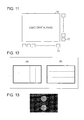
- FIG. 11 is a diagram depicting LEDs arranged on two sides of the liquid crystal panel.
- FIG. 12 is a diagram depicting two types of evaluation areas (a horizontal component evaluation area and a vertical component evaluation area).
- FIG. 13 is a diagram depicting an example of an input image.
- FIG. 14 is a diagram depicting an example of an approximate curve of horizontal components and an approximate curve of vertical components, the approximate curves generated from the input image depicted in FIG. 13 .
- FIG. 15 is a diagram depicting LEDs arranged in a matrix on the back of the liquid crystal panel.
- FIG. 16 is a diagram depicting temporal changes of each LED data for a plurality of input images which are continuously input.
- FIG. 17 is a diagram depicting an example of an input image.
- FIG. 18 depicts an existing technique and is a diagram depicting an example of LED data observed when the input image depicted in FIG. 17 is input.
- FIG. 19 depicts the existing technique and is a diagram depicting the liquid crystal transmittance observed when the input image depicted in FIG. 17 is input.
- FIG. 20 depicts the existing technique and is a diagram depicting the display luminance distribution observed when an LED driver drives LEDs based on the LED data depicted in FIG. 18 and a liquid crystal driver drives a liquid crystal panel based on the liquid crystal transmittance depicted in FIG. 19 .
- FIG. 21 depicts the existing technique and is a diagram depicting the actual luminance distribution observed when the LED driver drives the LEDs based on the LED data depicted in FIG. 18 .
- FIG. 22 depicts the existing technique and is a diagram depicting the liquid crystal transmittance corrected in consideration of the actual luminance distribution when the input image depicted in FIG. 17 is input.
- FIG. 23 depicts the existing technique and is a diagram depicting the display luminance distribution observed when the LED driver drives the LEDs based on the LED data depicted in FIG. 18 and the liquid crystal driver drives the liquid crystal panel based on the liquid crystal transmittance depicted in FIG. 22 .
- FIGS. 1 to 15 An embodiment of the present invention will be described as follows based on FIGS. 1 to 15 .
- FIG. 1 is a block diagram depicting an example of the configuration of principal portions of a liquid crystal display device (an image display device) 1 .
- the liquid crystal display device 1 includes a controlling portion 11 , a liquid crystal panel (a display panel) 12 , LEDs (a light source) 13 , a liquid crystal driver (a display panel driving means) 14 , and an LED driver (a light source driving means) 15 .
- the liquid crystal panel 12 is a liquid crystal display element on which pixels are arranged in a matrix. Each pixel includes subpixels in which color filters that allow red (R), green (G), and blue (B) lights to pass therethrough are disposed. Moreover, the liquid crystal panel 12 has a display surface on which an image can be displayed.
- the number of colors of the color filters disposed in the subpixel is not limited to three mentioned above and may be two or four, for example. Furthermore, in this embodiment, it is assumed that the number of pixels of the liquid crystal panel 12 is 1920 ⁇ 1080 (full HD). However, the number is not limited thereto, and the liquid crystal panel 12 may have an arbitrary number of pixels.
- the LEDs 13 emit light from the back (a surface opposite to a surface on which an image is displayed) side of the liquid crystal panel 12 via a light guide plate. That is, the LEDs 13 function as a backlight. As depicted in FIG. 1 , the LEDs 13 are arranged along one long side of the liquid crystal panel 12 . In this embodiment, it is assumed that 48 LEDs are arranged.
- the light source which is used as the backlight of the liquid crystal display device 1 is not limited to the LED and may be any light source.
- an edge light scheme is adopted and the LEDs 13 are arranged only on one long side of the liquid crystal panel 12 , but the arrangement is not limited thereto.
- the LEDs 13 may be arranged along the two sides: the long side and the short side of the liquid crystal panel 12 .
- a direct-type scheme may be adopted and the LEDs 13 may be arranged on the back side of the liquid crystal panel 12 .
- 48 LEDs 13 are arranged; however, an arbitrary number of LEDs 13 may be used.
- the liquid crystal driver 14 is a driving circuit that drives the liquid crystal panel 12 based on an instruction from the controlling portion 11 . Specifically, the liquid crystal driver 14 controls the liquid crystal transmittance of each pixel (each subpixel) by applying a voltage to each pixel (each subpixel) of the liquid crystal panel 12 .
- the LED driver 15 is a driving circuit that drives each LED 13 based on an instruction (LED data) from the controlling portion 11 . That is, the LED driver 15 controls the intensity of light emitted by each LED 13 . More specifically, the LED driver 15 acquires an LED data string from the controlling portion 11 and controls the output of each LED 13 based on the acquired LED data string.
- the LED data string is what is obtained by arranging the LED data indicating the output of each LED 13 in the order in which the LEDs 13 are arranged. That is, in this embodiment, the LED data string is what is obtained by arranging 48 pieces of LED data.
- the controlling portion 11 is formed of a microcomputer and so forth and controls the entire liquid crystal display device 1 by controlling the portions of the liquid crystal display device 1 .
- the controlling portion 11 has a configuration provided with, as functional blocks, an image evaluating portion (an image evaluating means) 21 , an LED data calculating portion (an approximate curve generating means, a light source data calculating means) 22 , and a liquid crystal transmittance calculating portion (a light transmittance calculating means) 23 .
- These functional blocks ( 21 to 23 ) of the controlling portion 11 may be implemented as a result of a central processing unit (CPU) reading a program stored in a storage device implemented by read only memory (ROM) or the like temporarily into a storing portion implemented by random access memory (RAM) or the like and executing the program. Moreover, the functional blocks ( 21 to 23 ) may be implemented by hardware, not software.
- CPU central processing unit
- ROM read only memory
- RAM random access memory
- the image evaluating portion 21 acquires an input image from the outside of the liquid crystal display device 1 and analyzes the acquired input image. Specifically, the image evaluating portion 21 divides the input image into a plurality of areas, identifies an evaluation value of each area, and generates an evaluation value string in which the evaluation values of the areas are arranged in order. At the same time, the image evaluating portion 21 identifies an evaluation value of the entire input image.
- the evaluation value is an indicator indicating the magnitude of the luminance of a certain region.
- the image evaluating portion 21 outputs the evaluation value string to the LED data calculating portion 22 and outputs the evaluation value of the entire input image to the liquid crystal transmittance calculating portion 23 .
- the evaluation value of the entire input image is referred to as an overall evaluation value.
- the LED data calculating portion 22 calculates LED data (light source data) based on the analysis result of the image evaluating portion 21 . Specifically, the LED data calculating portion 22 acquires the evaluation value string from the image evaluating portion 21 , generates an approximate curve based on the evaluation value string, and calculates LED data from the generated approximate curve. The LED data calculating portion 22 outputs the calculated LED data to the LED driver 15 . Moreover, the LED data calculating portion 22 outputs the generated approximate curve to the liquid crystal transmittance calculating portion 23 .
- the liquid crystal transmittance calculating portion 23 acquires an input image from the outside of the liquid crystal display device 1 and, at the same time, acquires the overall evaluation value from the image evaluating portion 21 and the approximate curve from the LED data calculating portion 22 . Then, the liquid crystal transmittance calculating portion 23 calculates a correction coefficient from the acquired input image, approximate curve, and overall evaluation value and calculates the liquid crystal transmittance (light transmittance) based on the acquired input image and the calculated correction coefficient. The liquid crystal transmittance calculating portion 23 outputs the calculated fluid volume transmittance to the liquid crystal driver 14 .
- the image evaluating portion 21 and the liquid crystal transmittance calculating portion 23 acquire an input image from the outside of the liquid crystal display device 1 ; however, the embodiment is not limited thereto. If the liquid crystal display device 1 includes a storing portion (not depicted), the image evaluating portion 21 and the liquid crystal transmittance calculating portion 23 may acquire an input image by reading an image from the storing portion.
- FIG. 2 is a flowchart depicting an example of the display processing which is performed by the liquid crystal display device 1 .
- the image evaluating portion 21 and the liquid crystal transmittance calculating portion 23 acquire an input image from the outside of the liquid crystal display device 1 (S 1 ).
- the image evaluating portion 21 divides the acquired input image into a plurality of areas (S 2 ).
- the image evaluating portion 21 identifies an evaluation value of each area and generates an evaluation value string in which the evaluation values of the areas are arranged in order (S 3 ).
- the image evaluating portion 21 identifies an overall evaluation value from the input image (S 4 ).
- the LED data calculating portion 22 generates an approximate curve based on the evaluation value string generated by the image evaluating portion 21 (S 5 ). Then, the LED data calculating portion 22 calculates LED data from the generated approximate curve (S 6 ).
- the liquid crystal transmittance calculating portion 23 calculates a correction coefficient from the acquired input image, the approximate curve generated by the LED data calculating portion 22 , and the overall evaluation value identified by the image evaluating portion 21 and calculates the liquid crystal transmittance based on the acquired input image and the calculated correction coefficient (S 7 ).
- the LED driver 15 drives the LEDs 13 based on the LED data calculated by the LED data calculating portion 22
- the liquid crystal driver 14 drives the liquid crystal panel 12 based on the liquid crystal transmittance calculated by the liquid crystal transmittance calculating portion 23 (S 8 ).
- an input image has 0 to 255 (8-bit)-step gradation
- a pixel is one pixel including RGB
- a picture element is an R, G, or B subpixel.
- the value of LED data is assumed to be 10 bit: 0 to 1023.
- FIG. 3 is a diagram depicting an outline of the processing example of the image evaluating portion 21 .
- the image evaluating portion 21 vertically divides an input image 41 depicted in FIG. 3( a ) into five areas 41 a to 41 e with respect to a long-side direction.
- the input image division method is not limited thereto.
- the input image 41 is vertically divided with respect to the long-side direction.
- the input image 41 is vertically divided with respect to the short-side direction.
- the number of areas, the area thereof, and so forth may be arbitrarily set.
- division into five areas 41 a to 41 e is performed, but other division may be performed as long as division into a plurality of areas is performed.
- the input image 41 is divided into five equal parts, but the five areas 41 a to 41 e may differ from one another.
- the number of areas is an odd number in order to obtain an evaluation value at a center of an input image.
- the larger the number of areas the higher the accuracy of evaluation.
- the method for extracting a representative value is not limited to the above-mentioned example.
- a pixel value in an area not a picture element value in the area, may be referred to.
- the average value of pixel values or picture element values in an area may be used as a representative value.
- a histogram of pixel values or picture element values in an area may be created and the most common pixel value or picture element value may be used as a representative value.
- the value of an arbitrary pixel or picture element in an area may be used as a representative value.
- the image evaluating portion 21 divides 0 to 255 into a plurality of levels and uses the value of the level corresponding to the representative value as an evaluation value. Specifically, the image evaluating portion 21 divides 0 to 255 into equal four parts and sets 0 to 63 as “level 0”, 64 to 127 as “level 1”, 128 to 191 as “level 2”, and 192 to 255 as “level 3”. For example, since the representative value of the area 41 a is 150, the evaluation value of the area 41 a is “2”.
- the image evaluating portion 21 identifies the evaluation values of the areas 41 a to 41 e and generates an evaluation value string (index) by arranging the identified evaluation values in order.
- the evaluation value string is “2, 3, 3, 3, 2”.
- the above-described way to divide levels may be carried out in any manner.
- 0 to 255 are divided into four equal parts, but the number of levels, the level range, and so forth may be arbitrarily set.
- the representative value may be used as an evaluation value as it is without level division.
- the image evaluating portion 21 identifies the maximum value of the picture elements included in the input image 41 as an overall evaluation value (frame level).
- the overall evaluation value is “200”.
- a method for identifying the overall evaluation value simply has to be the same as the above-described method for extracting the representative value.
- the image evaluating portion 21 makes evaluations on the input image 41 by dividing the input image 41 into predetermined areas and converts it into numbers in the form of an evaluation value string.
- the luminance distribution of the input image 41 can be grasped as a broad tendency with respect to the direction in which the LEDs 13 are arranged, such as a positive slope, a negative slope, a partial distribution, and a uniform distribution, and treated as numbers. That is, the image evaluating portion 21 approximates the luminance distribution of the input image 41 with respect to the direction in which the LEDs 13 are arranged and converts it into numbers.
- the luminance distribution of the input image 41 is the distribution of the magnitudes of luminance observed when the input image 41 is displayed and corresponds to the distribution of pixel values or picture element values of the input image 41 .
- the LED data calculating portion 22 When acquiring the evaluation value string from the image evaluating portion 21 , the LED data calculating portion 22 generates an approximate curve based on the acquired evaluation value string. In this example, as depicted in FIG. 4 , the LED data calculating portion 22 generates a secondary B spline curve based on the evaluation value string.
- a shape is obtained by interpolation which is performed on the spaces between the evaluation values such that the number of plot points of the final B spline curve becomes the number of LEDs 13 , that is, 48.
- the evaluation values are assumed to be x 1 , x 2 , . . . , x n .
- the number of divisions between the evaluation values is assumed to be m. Incidentally, (n ⁇ 1) ⁇ m is equal to the number of LEDs 13 .
- B spline interpolation calculates a value obtained by interpolating the spaces between three points from the values of the three points. That is, interpolation between x 1 and x 3 and interpolation of x 3 to x 5 , . . . , and x n-2 to x n are performed.
- the evaluation values of the three points include 2m LED plot points.
- the LED data calculating portion 22 generates an approximate curve whose amount of change (gradient) is less than or equal to a predetermined value.
- the LED data calculating portion 22 generates an approximate curve in which the value of a difference between adjacent plot points becomes less than or equal to a predetermined value.
- a secondary B spline curve is generated, but an arbitrary order may be used. By increasing the order, it is possible to perform dimming with a higher degree of accuracy. On the other hand, since the circuit size is increased with an increase in the order, the order is appropriately configured in accordance with an intended application. Moreover, in this example, a B spline curve is generated, but a method for generating an approximate curve may be an arbitrary method.
- the LED data calculating portion 22 calculates LED data by performing mapping to the LED data based on the interpolation values.
- the upper limit and lower limit bias of the LED data is configured separately and linear mapping is performed in such a way that the values of the LED data fall within that range.
- a luminance diffusing filter used in the existing technique has to be made again in a different optical system; however, the use of the present invention eliminates the need for an optical simulation for each liquid crystal display device and a luminance diffusing filter for each optical system.
- the liquid crystal transmittance calculating portion 23 derives a correction coefficient curve as described below based on the input image, the overall evaluation value, and the approximate curve and calculates the liquid crystal transmittance.
- a value obtained by subtracting the approximate curve from the maximum value of the evaluation value string (that is, a vertically-flipped shape) is used as a correction coefficient curve.
- the number of plot points of the approximate curve used in determining the LED data is the number of LEDs 13 ; in deriving the correction coefficient curve, an approximate curve having plot points whose number corresponds to the number of horizontal pixels of the liquid crystal panel 12 is calculated separately.
- “Assist(i,j,c)” is a correction coefficient.
- K is corrected intensity.
- LCD_rate(i,j)” becomes an intermediate value for deriving the correction coefficient.
- Offset is a value obtained by converting the 8-bit overall evaluation value (frame level) to make it possible to perform a comparison with the approximate curve and the evaluation value string.
- “Index_Max” is the maximum value of the evaluation value string (index).
- LCDP j is calculated by the following equations.
- LCDP j ( 1 - j / 2 ⁇ m ) 2 ⁇ x 1 + j / m ⁇ ( 1 - j / 2 ⁇ m ) ⁇ x 2 + ( j / 2 ⁇ m ) 2 ⁇ x 3 ⁇ ( 0 ⁇ j ⁇ 2 ⁇ m )
- LCDP j ( 1 - j / 2 ⁇ m ) 2 ⁇ x 3 + j / m ⁇ ( 1 - j / 2 ⁇ m ) ⁇ x 4 + ( j / 2 ⁇ m ) 2 ⁇ x 5 ⁇ ( 2 ⁇ m ⁇ j ⁇ 4 ⁇ m )
- LCDP j ( 1 - j / 2 ⁇ m ) 2 ⁇ x n - 2 + j / m ⁇ ( 1 - j / 2 ⁇ m ) ⁇ x n - 1 + (
- LCDP j is an integer and 0 ⁇ j ⁇ Nh LCD holds.
- m is the number of divisions between the evaluation values, and (n ⁇ 1) ⁇ m is equal to the number of horizontal pixels Nh LCD .
- n is the number of evaluation values or the number of areas.
- FIG. 6 is a diagram depicting the relationship between the picture element value of an input image and the liquid crystal transmittance.
- the horizontal axis is “Cin(i,j,c)” and the vertical axis is “Cout(i,j,c)”.
- the LED data calculated by the LED data calculating portion 22 and the liquid crystal transmittance calculated by the liquid crystal transmittance calculating portion 23 when the input image 61 depicted in FIG. 7 is input are depicted in FIG. 8 as a graph.
- the horizontal axis is an LED or a picture element (a pixel) corresponding to a position from the point A to the point B in FIG. 7 and the vertical axis is the value of the LED data or the liquid crystal transmittance.
- the LED data calculated by the LED data calculating portion 22 and the liquid crystal transmittance calculated by the liquid crystal transmittance calculating portion 23 are schematically depicted in FIG. 9 .
- a shade of color indicates the LED data value of each LED 13 and the liquid crystal transmittance of a picture element (a pixel) on the image.
- FIG. 10 a display image observed when the LED driver 15 drives the LEDs 13 based on the LED data depicted in FIG. 8 or 9 and the liquid crystal driver 14 drives the liquid crystal panel 12 based on the liquid crystal transmittance depicted in FIG. 8 or 9 is depicted.
- the LED data and the liquid crystal transmittance are calculated based an approximate curve obtained by approximating an input image, the approximate curve whose amount of change is less than or equal to a predetermined value, as compared to the existing dimming method depicted in FIGS. 12 to 15 , it is possible to prevent the occurrence of a local failure of video.
- the LEDs 13 are arranged only on the long side of the liquid crystal panel 12 , but the arrangement is not limited thereto.
- the LEDs 13 may be arranged along the long side and the short side of the liquid crystal panel 12 . That is, light may be allowed to enter the liquid crystal panel 12 from the two sides thereof.
- the image evaluating portion 21 configures two types of evaluation areas (a horizontal component evaluation area and a vertical component evaluation area). Specifically, the image evaluating portion 21 vertically divides an input image into five evaluation areas (horizontal component evaluation areas) with respect to the long-side direction (horizontal direction) as depicted in FIG. 12( a ) . At the same time, the image evaluating portion 21 vertically divides the input image into three evaluation areas (vertical component evaluation areas) with respect to the short-side direction (vertical direction) as depicted in FIG. 12( b ) .
- the image evaluating portion 21 identifies an evaluation value for each of the horizontal component evaluation areas and generates an evaluation value string of the horizontal components. At the same time, the image evaluating portion 21 identifies an evaluation value for each of the vertical component evaluation areas and generates an evaluation value string of the vertical components. Moreover, the image evaluating portion 21 identifies an overall evaluation value.
- the LED data calculating portion 22 generates an approximate curve of the horizontal components, the approximate curve obtained by approximating the evaluation value string of the horizontal components.
- the LED data calculating portion 22 generates an approximate curve of the vertical components, the approximate curve obtained by approximating the evaluation value string of the vertical components. For example, when an input image depicted in FIG. 13 is input, the LED data calculating portion 22 generates an approximate curve of horizontal components and an approximate curve of vertical components depicted in FIG. 14 .
- the LED data calculating portion 22 calculates LED data of the horizontal components by mapping the approximate curve of the horizontal components and calculates LED data of the vertical components by mapping the approximate curve of the vertical components.
- the LED data of the horizontal components is the LED data of the LEDs 13 on the long side
- the LED data of the vertical components is the LED data of the LEDs 13 on the short side.
- the liquid crystal transmittance calculating portion 23 derives a correction coefficient curve as follows based on the input image, the overall evaluation value, and the approximate curve of the horizontal components and the approximate curve of the vertical components and calculates the liquid crystal transmittance.
- a value obtained by subtracting the approximate curve from the maximum value of the evaluation value string that is, a vertically-flipped shape
- a value obtained by multiplying them is used as the correction coefficient curve.
- LCD_rate( i,j ) Offset+(Index_Max_ h ⁇ LCDP j )*(Index_Max_ v ⁇ LCDP i )/(Index_Max_ h *Index_Max_ v )
- LCDP j is calculated by the following equations.
- LCDP j ( 1 - j / 2 ⁇ m h ) 2 ⁇ x 1 + j / m h ⁇ ( 1 - j / 2 ⁇ m h ) ⁇ x 2 + ( j / 2 ⁇ m h ) 2 ⁇ x 3 ⁇ ( 0 ⁇ j ⁇ 2 ⁇ m h )
- LCDP j ( 1 - j / 2 ⁇ m h ) 2 ⁇ x 3 + j / m h ⁇ ( 1 - j / 2 ⁇ m h ) ⁇ x 4 + ( j / 2 ⁇ m h ) 2 ⁇ x 5 ⁇ ( 2 ⁇ m h ⁇ j ⁇ 4 ⁇ m h ) ...
- LCDP j ( 1 - j / 2 ⁇ m h ) 2 ⁇ x nh - 2 + j / m h
- LCDP j is an integer and 0 ⁇ j ⁇ Nh LCD .
- m h is the number of divisions between the evaluation values of the horizontal components, and (nh ⁇ 1) ⁇ m h is equal to the number of horizontal pixels Nh LCD .
- nh is the number of horizontal component evaluation areas.
- LCDP i is calculated by the following equations.
- LCDP i is an integer and 0 ⁇ i ⁇ Nv LCD .
- m v is the number of divisions between the evaluation values of the vertical components, and (nv ⁇ 1) ⁇ m v is equal to the number of vertical pixels Nv LCD .
- nv is the number of vertical component evaluation areas.
- the LEDs 13 are arranged on the long side of the liquid crystal panel 12 , but the arrangement is not limited thereto.
- the LEDs 13 may be arranged in a matrix on the back of the liquid crystal panel 12 .
- the image evaluating portion 21 configures two types of evaluation areas (a horizontal component evaluation area and a vertical component evaluation area) and generates an evaluation value string of the horizontal components and an evaluation value string of the vertical components. Moreover, the image evaluating portion 21 identifies an overall evaluation value.
- the LED data calculating portion 22 generates an approximate curve of the horizontal components and an approximate curve of the vertical components corresponding to the evaluation value string of the horizontal components and the evaluation value string of the vertical components, respectively. Then, the LED data calculating portion 22 calculates LED data of the horizontal components and LED data of the vertical components from the approximate curve of the horizontal components and the approximate curve of the vertical components, respectively.
- the liquid crystal transmittance calculating portion 23 calculates the liquid crystal transmittance based on the input image, the overall evaluation value, and the approximate curve of the horizontal components and the approximate curve of the vertical components.
- the amount of change in LED data is set so as to be less than or equal to a predetermined value in a physical dimension; in addition, the amount of change in LED data may be set so as to be less than or equal to a predetermined value in a temporal dimension.
- LED data when moving images are displayed, LED data may be determined in such a way that a difference between LED data for a certain input image and LED data for the next input image becomes less than or equal to a predetermined value.
- Pre_LED is LED data for an input image before the certain input image described above (is “LED_out” for an input image before the certain input image).
- New_LED is LED data calculated from the approximate curve obtained by approximating the evaluation value string generated from the certain input image.
- T is a correction coefficient and is assumed to be an arbitrary number from 0 to 1.
- the amount of change in an intermediate value “LCD_rate(i,j)” used to derive the liquid crystal transmittance may be set so as to be less than or equal to a predetermined value.
- the intermediate value when moving images are displayed, the intermediate value may be determined in such a way that a difference between the intermediate value used to derive the liquid crystal transmittance of a certain input image and the intermediate value used to derive the liquid crystal transmittance of the next input image becomes less than or equal to a predetermined value.
- Pre_LCD_rate(i,j) is an intermediate value for an input image before the certain input image described above (is “LCD_rate(i,j)” for an input image before the certain input image).
- “New_LCD_rate(i,j)” is an intermediate value calculated from the approximate curve obtained by approximating the evaluation value string generated from the certain input image.
- T is a correction coefficient and is assumed to be an arbitrary number from 0 to 1.
- a liquid crystal display device equipped with a liquid crystal panel is depicted as an example, but the display device is not limited thereto. Any display device may be used as long as the display device has a backlight and can configure the light transmittance of a display panel, and the display device may be, for example, a sign such as color Colton.
- each block of the liquid crystal display device 1 in particular, the controlling portion 11 may be configured by using hardware logic or may be implemented by software by using a CPU as follows.
- the liquid crystal display device 1 includes a central processing unit (CPU) that executes an instruction of a control program implementing the functions, read only memory (ROM) storing the above-described program, random access memory (RAM) in which the above-described program is expanded, a storage device (a recording medium), such as memory, which stores the above-described program and various data, and so forth.
- CPU central processing unit
- ROM read only memory
- RAM random access memory
- storage device a recording medium
- the object of the present invention can also be achieved by supplying a recording medium on which a program code (an execute format program, an intermediate code program, a source program) of the control program of the liquid crystal display device 1 which is software implementing the above-described functions is recorded in such a way as to allow a computer to read the program code to the liquid crystal display device 1 and making the computer (or the CPU or the MPU) read and execute the program code recorded on the recording medium.
- a program code an execute format program, an intermediate code program, a source program
- tapes such as magnetic tapes and cassette tapes
- disks including magnetic disks such as Floppy® disks/hard disks and optical disks such as CD-ROMs/MOs/MDs/DVDs/CD-Rs
- cards such as IC cards (including memory cards)/optical cards
- semiconductor memory such as mask ROM/EPROM/EEPROM®/flash ROM, or the like
- the liquid crystal display device 1 may be configured so as to be connectable to a communication network, and the above-described program code may be supplied thereto via the communication network.
- This communication network is not limited to a particular communication network, and, for example, the Internet, an intranet, an extranet, a LAN, an ISDN, a VAN, a CATV communication network, a virtual private network, a telephone network, a mobile communication network, a satellite communication network, and so forth can be used.
- a transmission medium forming the communication network is not limited to a particular transmission medium, and, for example, both wired media such as IEEE1394, a USB, a power-line carrier, a cable TV circuit, a telephone line, and an ADSL and wireless media such as infrared radiation such as IrDA and remote control, Bluetooth®, 802.11 radio, HDR, a mobile telephone network, a satellite circuit, and a terrestrial digital network can be used.
- wired media such as IEEE1394, a USB, a power-line carrier, a cable TV circuit, a telephone line, and an ADSL and wireless media such as infrared radiation such as IrDA and remote control, Bluetooth®, 802.11 radio, HDR, a mobile telephone network, a satellite circuit, and a terrestrial digital network
- the present invention can also be implemented in the form of a computer data signal embedded in a carrier wave, the computer data signal which is an embodiment of the above-described program code by electronic transmission.
- the present invention can be used in an image display device having the function of controlling the luminance of a backlight based on an input image.
Abstract
Description
LCD_rate(i,j)=Offset+(Index_Max−LCDPj)/Index_Max
Assist(i,j,c)=(1−Cin(i,j,c))*LCD_rate(i,j)*K
Cout(i,j,c)=Cin(i,j,c)+(Cin(i,j,c)*Assist(i,j,c))
LEDPj=(1−j/2m)2 x 1 +j/m(1−j/2m)x 2+(j/2m)2 x 3.
LCD_rate(i,j)=Offset+(Index_Max−LCDPj)/Index_Max
Assist(i,j,c)=(1−Cin(i,j,c))*LCD_rate(i,j)*K
Cout(i,j,c)=Cin(i,j,c)+(Cin(i,j,c)*Assist(i,j,c))
Here, “Cin(i,j,c)” is a picture element value (c=R or G or B) of a pixel in the i-th row and the j-th column of the input image. Moreover, “Cout(i,j,c)” is the liquid crystal transmittance of a picture element (c=R or G or B) of the pixel in the i-th row and the j-th column. Furthermore, “Assist(i,j,c)” is a correction coefficient. “K” is corrected intensity. “LCD_rate(i,j)” becomes an intermediate value for deriving the correction coefficient. In addition, “Offset” is a value obtained by converting the 8-bit overall evaluation value (frame level) to make it possible to perform a comparison with the approximate curve and the evaluation value string. Moreover, “Index_Max” is the maximum value of the evaluation value string (index).
LCD_rate(i,j)=Offset+(Index_Max_h−LCDPj)*(Index_Max_v−LCDPi)/(Index_Max_h*Index_Max_v)
Assist(i,j,c)=(1−Cin(i,j,c))*LCD_rate(i,j)*K
Cout(i,j,c)=Cin(i,j,c)+(Cin(i,j,c)*Assist(i,j,c))
LED_data_f(m,n)=(LED_data_h_#n+LED_data_v_#m)/2 or
LED_data_f(m,n)=LED_data_h_#n*LED_data_v_#m.
LED_out=Pre_LED+(New_LED−Pre_LED)*T.
LCD_rate(i,j)=Pre_LCD_rate(i,j)+(New_LCD_rate(i,j)−Pre_LCD_rate(i,j))*T.
-
- 1 liquid crystal display device (image display device)
- 11 controlling portion
- 12 liquid crystal panel (display panel)
- 13 LED (light source)
- 14 liquid crystal driver (display panel driving means)
- 15 LED driver (light source driving means)
- 21 image evaluating portion (image evaluating means)
- 22 LED data calculating portion (approximate curve generating means, light source data calculating means)
- 23 liquid crystal transmittance calculating portion (light transmittance calculating means)
Claims (4)
Applications Claiming Priority (3)
| Application Number | Priority Date | Filing Date | Title |
|---|---|---|---|
| JP2012197789 | 2012-09-07 | ||
| JP2012-197789 | 2012-09-07 | ||
| PCT/JP2013/071328 WO2014038336A1 (en) | 2012-09-07 | 2013-08-07 | Image display device, control method for image display device, control program, and recording medium |
Publications (2)
| Publication Number | Publication Date |
|---|---|
| US20150325175A1 US20150325175A1 (en) | 2015-11-12 |
| US9542893B2 true US9542893B2 (en) | 2017-01-10 |
Family
ID=50236952
Family Applications (1)
| Application Number | Title | Priority Date | Filing Date |
|---|---|---|---|
| US14/410,457 Expired - Fee Related US9542893B2 (en) | 2012-09-07 | 2013-08-07 | Image display device, recording medium, and method to control light sources based upon generated approximate curves |
Country Status (3)
| Country | Link |
|---|---|
| US (1) | US9542893B2 (en) |
| JP (1) | JP6174032B2 (en) |
| WO (1) | WO2014038336A1 (en) |
Families Citing this family (3)
| Publication number | Priority date | Publication date | Assignee | Title |
|---|---|---|---|---|
| JP6188298B2 (en) * | 2012-09-07 | 2017-08-30 | シャープ株式会社 | Image display device, control method for image display device, control program, and recording medium |
| CN104575405B (en) * | 2015-02-04 | 2017-08-25 | 京东方科技集团股份有限公司 | A kind of method, the display device of adjusting display device backlight illumination |
| CN113470588B (en) * | 2021-06-29 | 2022-11-15 | 腾讯科技(深圳)有限公司 | Driving method of liquid crystal display screen, electronic equipment and driving chip |
Citations (17)
| Publication number | Priority date | Publication date | Assignee | Title |
|---|---|---|---|---|
| US20050184952A1 (en) | 2004-02-09 | 2005-08-25 | Akitoyo Konno | Liquid crystal display apparatus |
| US20060139270A1 (en) * | 2004-12-29 | 2006-06-29 | Lg.Philips Lcd Co., Ltd. | Method and apparatus for driving liquid crystal dispaly device |
| US20070152926A1 (en) * | 2005-12-29 | 2007-07-05 | Lg.Philips Lcd Co., Ltd. | Apparatus and method for driving liquid crystal display device |
| JP2008051905A (en) | 2006-08-22 | 2008-03-06 | Sharp Corp | Liquid crystal display device and backlight driving method therefor |
| US20080129680A1 (en) * | 2006-12-01 | 2008-06-05 | Sony Corporation | Apparatus and method for controlling backlight and liquid crystal display |
| US20080297467A1 (en) * | 2007-05-30 | 2008-12-04 | Wintek Corporation | Method for backlight modulation and image processing |
| US20090140975A1 (en) | 2007-12-04 | 2009-06-04 | Ryosuke Nonaka | Image display apparatus and image display method |
| JP2009192963A (en) | 2008-02-18 | 2009-08-27 | Sharp Corp | Image display device and image display method |
| US20090219244A1 (en) * | 2008-02-29 | 2009-09-03 | Fletcher Bergen Albert | System and method for adjusting an intensity value and a backlight level for a display of an electronic device |
| US20090284545A1 (en) * | 2008-05-19 | 2009-11-19 | Hidekazu Watanabe | Display apparatus, display control method, and display control program |
| US20100066657A1 (en) * | 2008-04-16 | 2010-03-18 | Lg Display Co., Ltd. | Liquid crystal display |
| US20100066752A1 (en) * | 2008-09-18 | 2010-03-18 | Victor Company Of Japan, Limited | Liquid crystal display device and image display method thereof |
| JP2010256912A (en) | 2004-02-09 | 2010-11-11 | Hitachi Ltd | Lighting device, image display apparatus with the same, and image display method |
| US20100295877A1 (en) * | 2007-11-05 | 2010-11-25 | Ju Ho Yun | Liquid crystal display device and method for controlling back-light brightness |
| US20110157255A1 (en) * | 2009-12-30 | 2011-06-30 | Ching-Fu Hsu | System and method for modulating backlight |
| US20150302789A1 (en) * | 2014-02-10 | 2015-10-22 | Synaptics Display Devices Kk | Display device, display panel driver and drive method of display panel |
| US20160035293A1 (en) * | 2014-07-29 | 2016-02-04 | Synaptics Display Devices Gk | Device and method for color adjustment and gamma correction and display panel driver using the same |
Family Cites Families (3)
| Publication number | Priority date | Publication date | Assignee | Title |
|---|---|---|---|---|
| JP4237220B2 (en) * | 2006-11-13 | 2009-03-11 | シャープ株式会社 | Transmission type display device |
| JP5203854B2 (en) * | 2008-08-28 | 2013-06-05 | 株式会社東芝 | Information processing apparatus, image display apparatus and method |
| JP4818351B2 (en) * | 2008-12-25 | 2011-11-16 | 株式会社東芝 | Image processing apparatus and image display apparatus |
-
2013
- 2013-08-07 WO PCT/JP2013/071328 patent/WO2014038336A1/en active Application Filing
- 2013-08-07 US US14/410,457 patent/US9542893B2/en not_active Expired - Fee Related
- 2013-08-07 JP JP2014534255A patent/JP6174032B2/en not_active Expired - Fee Related
Patent Citations (18)
| Publication number | Priority date | Publication date | Assignee | Title |
|---|---|---|---|---|
| JP2010256912A (en) | 2004-02-09 | 2010-11-11 | Hitachi Ltd | Lighting device, image display apparatus with the same, and image display method |
| US20050184952A1 (en) | 2004-02-09 | 2005-08-25 | Akitoyo Konno | Liquid crystal display apparatus |
| US20060139270A1 (en) * | 2004-12-29 | 2006-06-29 | Lg.Philips Lcd Co., Ltd. | Method and apparatus for driving liquid crystal dispaly device |
| US20070152926A1 (en) * | 2005-12-29 | 2007-07-05 | Lg.Philips Lcd Co., Ltd. | Apparatus and method for driving liquid crystal display device |
| JP2008051905A (en) | 2006-08-22 | 2008-03-06 | Sharp Corp | Liquid crystal display device and backlight driving method therefor |
| US20080129680A1 (en) * | 2006-12-01 | 2008-06-05 | Sony Corporation | Apparatus and method for controlling backlight and liquid crystal display |
| US20080297467A1 (en) * | 2007-05-30 | 2008-12-04 | Wintek Corporation | Method for backlight modulation and image processing |
| US20100295877A1 (en) * | 2007-11-05 | 2010-11-25 | Ju Ho Yun | Liquid crystal display device and method for controlling back-light brightness |
| US20090140975A1 (en) | 2007-12-04 | 2009-06-04 | Ryosuke Nonaka | Image display apparatus and image display method |
| JP2009139470A (en) | 2007-12-04 | 2009-06-25 | Toshiba Corp | Image display device, and image display method |
| JP2009192963A (en) | 2008-02-18 | 2009-08-27 | Sharp Corp | Image display device and image display method |
| US20090219244A1 (en) * | 2008-02-29 | 2009-09-03 | Fletcher Bergen Albert | System and method for adjusting an intensity value and a backlight level for a display of an electronic device |
| US20100066657A1 (en) * | 2008-04-16 | 2010-03-18 | Lg Display Co., Ltd. | Liquid crystal display |
| US20090284545A1 (en) * | 2008-05-19 | 2009-11-19 | Hidekazu Watanabe | Display apparatus, display control method, and display control program |
| US20100066752A1 (en) * | 2008-09-18 | 2010-03-18 | Victor Company Of Japan, Limited | Liquid crystal display device and image display method thereof |
| US20110157255A1 (en) * | 2009-12-30 | 2011-06-30 | Ching-Fu Hsu | System and method for modulating backlight |
| US20150302789A1 (en) * | 2014-02-10 | 2015-10-22 | Synaptics Display Devices Kk | Display device, display panel driver and drive method of display panel |
| US20160035293A1 (en) * | 2014-07-29 | 2016-02-04 | Synaptics Display Devices Gk | Device and method for color adjustment and gamma correction and display panel driver using the same |
Non-Patent Citations (2)
| Title |
|---|
| International Search Report PCT/ISA/210 for International Application No. PCT/JP2013/071328 Dated Nov. 12, 2013. |
| Written Opinion of the International Searching Authority PCT/ISA/237 for International Application No. PCT/JP2013/071328 Dated Nov. 12, 2013. |
Also Published As
| Publication number | Publication date |
|---|---|
| US20150325175A1 (en) | 2015-11-12 |
| JP6174032B2 (en) | 2017-08-02 |
| JPWO2014038336A1 (en) | 2016-08-08 |
| WO2014038336A1 (en) | 2014-03-13 |
Similar Documents
| Publication | Publication Date | Title |
|---|---|---|
| US10930225B2 (en) | Display control method and apparatus of backlight sources, and display device | |
| CN109064979B (en) | Image display processing method and device, display device and storage medium | |
| US9601062B2 (en) | Backlight dimming method and liquid crystal display using the same | |
| JP5595516B2 (en) | Method and system for backlight control using statistical attributes of image data blocks | |
| US11270657B2 (en) | Driving method, driving apparatus, display device and computer readable medium | |
| CN111968570B (en) | Display compensation information acquisition method, display compensation method and device | |
| KR101796718B1 (en) | Dynamic dimming led backlight | |
| US20180047345A1 (en) | Dynamic dimming led backlight for lcd array | |
| KR101337076B1 (en) | Liquid crystal display device and driving method having the same | |
| US20110317074A1 (en) | Display device and contrast enhancement method thereof | |
| US10460680B2 (en) | Flexible display panel and display method thereof | |
| JP2008203292A (en) | Image display device and image display method | |
| KR101990335B1 (en) | Data clipping method and device, and display device using the same | |
| CN104751807A (en) | Method and device for regulating backlight brightness and liquid crystal display device | |
| CN104115215B (en) | Video display devices and radiovisor | |
| US9401115B2 (en) | Liquid crystal display with a higher luminance sub-pixel including controllable light emission subsections | |
| US20110063201A1 (en) | Method, system and apparatus for power saving backlight | |
| US9542893B2 (en) | Image display device, recording medium, and method to control light sources based upon generated approximate curves | |
| US20200160492A1 (en) | Image Adjustment Method and Device, Image Display Method and Device, Non-Transitory Storage Medium | |
| WO2019148667A1 (en) | Method and device employing backlight partitioning to display image having high dynamic contrast ratio | |
| US11308895B2 (en) | Liquid crystal display device, image displaying method thereof, and backlight control device for local dimming | |
| US20110063331A1 (en) | Method, system and apparatus for power saving backlight | |
| JP6505007B2 (en) | BACKLIGHT CONTROL DEVICE, IMAGE DISPLAY DEVICE, AND BACKLIGHT CONTROL METHOD | |
| CN108962155A (en) | Luminance regulating method and display | |
| US20200064688A1 (en) | Local dimming system and method adaptable to a backlight of a display |
Legal Events
| Date | Code | Title | Description |
|---|---|---|---|
| AS | Assignment |
Owner name: SHARP KABUSHIKI KAISHA, JAPAN Free format text: ASSIGNMENT OF ASSIGNORS INTEREST;ASSIGNORS:YAMAGUCHI, NORIAKI;KONDOH, NAOKO;YOSHIDA, SHIGETO;REEL/FRAME:034580/0051 Effective date: 20141022 |
|
| STCF | Information on status: patent grant |
Free format text: PATENTED CASE |
|
| FEPP | Fee payment procedure |
Free format text: MAINTENANCE FEE REMINDER MAILED (ORIGINAL EVENT CODE: REM.); ENTITY STATUS OF PATENT OWNER: LARGE ENTITY |
|
| LAPS | Lapse for failure to pay maintenance fees |
Free format text: PATENT EXPIRED FOR FAILURE TO PAY MAINTENANCE FEES (ORIGINAL EVENT CODE: EXP.); ENTITY STATUS OF PATENT OWNER: LARGE ENTITY |
|
| STCH | Information on status: patent discontinuation |
Free format text: PATENT EXPIRED DUE TO NONPAYMENT OF MAINTENANCE FEES UNDER 37 CFR 1.362 |
|
| FP | Lapsed due to failure to pay maintenance fee |
Effective date: 20210110 |