JP6505007B2 - BACKLIGHT CONTROL DEVICE, IMAGE DISPLAY DEVICE, AND BACKLIGHT CONTROL METHOD - Google Patents
BACKLIGHT CONTROL DEVICE, IMAGE DISPLAY DEVICE, AND BACKLIGHT CONTROL METHOD Download PDFInfo
- Publication number
- JP6505007B2 JP6505007B2 JP2015239019A JP2015239019A JP6505007B2 JP 6505007 B2 JP6505007 B2 JP 6505007B2 JP 2015239019 A JP2015239019 A JP 2015239019A JP 2015239019 A JP2015239019 A JP 2015239019A JP 6505007 B2 JP6505007 B2 JP 6505007B2
- Authority
- JP
- Japan
- Prior art keywords
- partial
- value
- average value
- calculation unit
- weighted average
- Prior art date
- Legal status (The legal status is an assumption and is not a legal conclusion. Google has not performed a legal analysis and makes no representation as to the accuracy of the status listed.)
- Expired - Fee Related
Links
- 238000000034 method Methods 0.000 title description 9
- 238000004364 calculation method Methods 0.000 claims description 149
- 238000001514 detection method Methods 0.000 claims description 16
- 235000019557 luminance Nutrition 0.000 description 85
- 230000002093 peripheral effect Effects 0.000 description 19
- 238000010586 diagram Methods 0.000 description 10
- 230000003287 optical effect Effects 0.000 description 6
- 238000012935 Averaging Methods 0.000 description 5
- 230000000694 effects Effects 0.000 description 3
- 230000006870 function Effects 0.000 description 3
- PEDCQBHIVMGVHV-UHFFFAOYSA-N Glycerine Chemical compound OCC(O)CO PEDCQBHIVMGVHV-UHFFFAOYSA-N 0.000 description 2
- 239000004973 liquid crystal related substance Substances 0.000 description 2
- 235000000533 Rosa gallica Nutrition 0.000 description 1
- 244000181025 Rosa gallica Species 0.000 description 1
- 238000005282 brightening Methods 0.000 description 1
- 239000003086 colorant Substances 0.000 description 1
- 230000007423 decrease Effects 0.000 description 1
- 230000007812 deficiency Effects 0.000 description 1
- 238000002834 transmittance Methods 0.000 description 1
Images


Landscapes
- Liquid Crystal Display Device Control (AREA)
- Control Of Indicators Other Than Cathode Ray Tubes (AREA)
- Liquid Crystal (AREA)
Description
本発明は、バックライト制御装置、画像表示装置及びバックライト制御方法に関し、特に、部分領域毎にバックライトの明るさを制御するバックライト制御装置、画像表示装置及びバックライト制御方法に関する。 The present invention relates to a backlight control device, an image display device, and a backlight control method, and more particularly to a backlight control device, an image display device, and a backlight control method for controlling the brightness of the backlight for each partial area.
液晶表示装置等、バックライトを備えた画像表示装置では、バックライトのエリアを区切って、部分的に発光輝度を制御することにより、コントラストの向上と消費電力の低減とを行ってきた。近年、HDR(High Dynamic Range)規格等もあり、消費電力低減だけでなく、例えば、明るく輝く部分の描写力等がより求められるようになってきている。 In an image display device provided with a backlight such as a liquid crystal display device, improvement in contrast and reduction in power consumption have been achieved by dividing the area of the backlight and partially controlling the light emission luminance. In recent years, there are HDR (High Dynamic Range) standards and the like, and not only power consumption reduction, but also, for example, depiction power of brightly bright portions etc. are being sought more.
例えば、特許文献1に記載された画像表示装置は、各エリア内の画素の輝度の最大値を検出し、また、各エリア内の画素の輝度の平均値を算出し、好適な値に設定された閾値と各エリアの輝度最大値とを比較する。そして、この画像表示装置は、閾値よりもエリア輝度最大値の方が大きい場合、最大値に対応する値を出力し、エリア輝度最大値が閾値以下の場合、平均値に対応する値を出力する。
For example, the image display device described in
特許文献1では、上記のように、バックライトであるLED(Light Emitting Diode)の出力値が決定される。閾値が好適な値に設定されていれば、高階調表示が行われるべき画素を含むエリアにおいて、LED出力値が領域最大値に基づいて決定されることにより、輝度不足の発生が抑制される。一方、高階調表示が行われるべき画素を含まないエリアにおいては、LED出力値が領域平均値に基づいて決定されることにより消費電力が低減される。
In
しかしながら、ある値に設定された閾値とエリア輝度最大値とを比較して、バックライトであるLEDの出力値が決定される場合、エリア輝度最大値が閾値を挟んで変化すると、バックライトの輝度に不連続が生じる。ここでバックライトは、LEDが用いられているが、他の光源であっても、同じである。 However, when the output value of the LED that is the backlight is determined by comparing the threshold set to a certain value with the area brightness maximum value, if the area brightness maximum value changes across the threshold, the backlight brightness There is a discontinuity in the Here, LEDs are used as the backlight, but the same is true for other light sources.
例えば、時間軸で考えた場合、エリア輝度最大値が閾値を挟んで変化を繰り返すと、バックライトの輝度は、明るくなったり暗くなったりを繰り返し、視聴者に違和感を与える。また、映像に含まれる意図しない信号(ノイズ)が原因で上記のような状況を生じる場合もあり、大きく画質劣化する場合がある。 For example, in the case of the time axis, when the area brightness maximum value repeatedly changes with the threshold value interposed, the backlight brightness repeats brightening and darkening, giving the viewer a sense of discomfort. In addition, the above situation may occur due to an unintended signal (noise) included in the video, and the image quality may be greatly degraded.
閾値や、閾値と比較する値を変えても、上記のような問題は同じく発生する。 Even if the threshold value or the value to be compared with the threshold value is changed, the above-described problem also occurs.
そこで、本発明は、バックライトの省電力制御と高輝度制御とを連続的に行うことができるようにすることを目的とする。 Therefore, an object of the present invention is to enable power saving control and high brightness control of a backlight to be performed continuously.
本発明の1態様に係るバックライト制御装置は、入力画像の画素毎に特徴量を算出する特徴量算出部と、前記入力画像に含まれる部分領域における前記特徴量の最大値である部分最大値を、前記入力画像に含まれる部分領域毎に検出する部分最大値検出部と、前記部分領域における前記特徴量の平均値である部分平均値を、前記部分領域毎に算出する部分平均値算出部と、予め定められた範囲における前記特徴量の平均値が大きいほど前記部分平均値の割合が高くなるように加重平均係数を算出する加重平均係数算出部と、前記部分領域毎に、前記加重平均係数を用いて、前記部分最大値及び前記部分平均値の加重平均値を算出する加重平均算出部と、前記加重平均値の平均値である基準平均値を算出する平均値算出部と、前記部分領域毎に、前記加重平均値と、前記基準平均値とを比較するために、前記基準平均値を用いて前記加重平均値の偏差を求める比較部と、バックライトの全体の明るさを示す全体制御値に、前記偏差に設定値を乗算した値を加算することで、前記設定値に応じて、前記比較部の比較結果に基づいて、前記部分領域毎に、前記加重平均値が前記基準平均値よりも大きいほど、前記バックライトの対応する部分が明るくなるように、又は、前記部分領域の明るさが同じとなるように、部分制御値を算出する部分制御値算出部と、を備えることを特徴とする。 A backlight control device according to one aspect of the present invention includes a feature amount calculation unit that calculates a feature amount for each pixel of an input image, and a partial maximum value that is the maximum value of the feature amounts in partial regions included in the input image. A partial maximum value detection unit that detects each partial region included in the input image, and a partial average value calculation unit that calculates, for each partial region, a partial average value that is an average value of the feature amounts in the partial region And a weighted average coefficient calculation unit that calculates a weighted average coefficient so that the proportion of the partial average value increases as the average value of the feature amounts in a predetermined range increases, and the weighted average for each partial region A weighted average calculation unit that calculates a weighted average value of the partial maximum value and the partial average value using a coefficient; an average value calculation unit that calculates a reference average value that is an average value of the weighted average values; For each area Said weighted average value, for comparing the reference average value, a comparison unit for determining the deviation of the weighted average value with the reference average value, the overall control value indicating the brightness of the entire backlight, By adding a value obtained by multiplying the deviation by a set value , the weighted average value is larger than the reference average value for each of the partial areas based on the comparison result of the comparison unit according to the set value. as the as the corresponding portion of the backlight becomes brighter, or, as the brightness of the partial region is equal, and wherein Rukoto comprises a partial control value calculating unit for calculating a partial control value, the Do.
本発明の1態様に係る画像表示装置は、バックライトと、入力画像の画素毎に特徴量を算出する特徴量算出部と、前記入力画像に含まれる部分領域における前記特徴量の最大値である部分最大値を、前記入力画像に含まれる部分領域毎に検出する部分最大値検出部と、前記部分領域における前記特徴量の平均値である部分平均値を、前記部分領域毎に算出する部分平均値算出部と、予め定められた範囲における前記特徴量の平均値が大きいほど前記部分平均値の割合が高くなるように加重平均係数を算出する加重平均係数算出部と、前記部分領域毎に、前記加重平均係数を用いて、前記部分最大値及び前記部分平均値の加重平均値を算出する加重平均算出部と、前記加重平均値の平均値である基準平均値を算出する平均値算出部と、前記部分領域毎に、前記加重平均値と、前記基準平均値とを比較するために、前記基準平均値を用いて前記加重平均値の偏差を求める比較部と、バックライトの全体の明るさを示す全体制御値に、前記偏差に設定値を乗算した値を加算することで、前記設定値に応じて、前記比較部の比較結果に基づいて、前記部分領域毎に、前記加重平均値が前記基準平均値よりも大きいほど、前記バックライトの対応する部分が明るくなるように、又は、前記部分領域の明るさが同じとなるように、部分制御値を算出する部分制御値算出部と、前記入力画像に基づいて画像を表示する表示部と、を備え、前記バックライトは、前記部分制御値に基づいて、部分毎に明るさを制御することを特徴とする。 The image display device according to one aspect of the present invention is a backlight, a feature amount calculation unit that calculates a feature amount for each pixel of an input image, and a maximum value of the feature amounts in partial areas included in the input image. A partial maximum value detection unit that detects a partial maximum value for each partial region included in the input image, and a partial average that calculates a partial average value that is an average value of the feature amounts in the partial region for each partial region A value calculation unit, a weighted average coefficient calculation unit that calculates a weighted average coefficient so that the proportion of the partial average value increases as the average value of the feature amounts in a predetermined range increases, and for each of the partial regions, A weighted average calculation unit that calculates a weighted average value of the partial maximum value and the partial average value using the weighted average coefficient; and an average value calculation unit that calculates a reference average value that is an average value of the weighted average values , Said part For each band, and the weighted average value, for comparing the reference average value, a comparison unit for determining the deviation of the weighted average value with the reference average value, the whole showing the overall brightness of the backlight By adding a value obtained by multiplying the deviation to the setting value to the control value, the weighted average value is the reference average value for each of the partial areas based on the comparison result of the comparing unit according to the setting value. larger than the value, as described above corresponding portion of the backlight becomes brighter, or such that the brightness of the partial region is equal, a partial control value calculating unit for calculating a partial control value, the input image and a display unit for displaying an image based on the previous SL backlight, based on the partial control value, and controlling the brightness for each part.
本発明の1態様に係るバックライト制御方法は、入力画像の画素毎に特徴量を算出し、前記入力画像に含まれる部分領域における前記特徴量の最大値である部分最大値を、前記入力画像に含まれる部分領域毎に検出し、前記部分領域における前記特徴量の平均値である部分平均値を、前記部分領域毎に算出し、予め定められた範囲における前記特徴量の平均値が大きいほど前記部分平均値の割合が高くなるように加重平均係数を算出し、前記部分領域毎に、前記加重平均係数を用いて、前記部分最大値及び前記部分平均値の加重平均値を算出し、前記加重平均値の平均値である基準平均値を算出し、前記部分領域毎に、前記基準平均値を用いて前記加重平均値の偏差を求めることで、前記加重平均値と、前記基準平均値とを比較して、前記部分領域毎に、バックライトの全体の明るさを示す全体制御値に、前記偏差に設定値を乗算した値を加算することで、前記設定値に応じて、前記加重平均値が前記基準平均値よりも大きいほど、前記バックライトの対応する部分が明るくなるように、又は、前記部分領域の明るさが同じとなるように、部分制御値を算出することを特徴とする。 The backlight control method according to one embodiment of the present invention calculates a feature value for each pixel of the input image, a partial maximum value is the maximum value of the feature amount in a partial region included in the input image, the input image Is detected for each partial region included in the partial region, and a partial average value that is an average value of the feature amounts in the partial regions is calculated for each partial region, and the larger the average value of the feature amounts in a predetermined range The weighted average coefficient is calculated such that the proportion of the partial average value is high, and the weighted average value of the partial maximum value and the partial average value is calculated using the weighted average coefficient for each of the partial areas, The weighted average value and the reference average value are calculated by calculating a reference average value that is an average value of weighted average values, and determining the deviation of the weighted average value using the reference average value for each of the partial areas. Compare the above parts For each region, the total control value indicating the brightness of the entire backlight, by adding the value obtained by multiplying the set value to the deviation, according to the setting value, the weighted average value from the reference average value The partial control value is calculated so that the corresponding part of the backlight becomes brighter , or the partial area has the same brightness, as the larger the value is.
本発明の一態様によれば、閾値を用いて制御を行っていないため、バックライトの省電力制御と高輝度制御とを連続的に行うことができる。 According to one aspect of the present invention, since control is not performed using the threshold, power saving control and high brightness control of the backlight can be performed continuously.
実施の形態1.
図1は、実施の形態1に係る画像処理装置100の構成を概略的に示すブロック図である。
画像処理装置100は、映像入力端子101と、特徴量算出部102と、部分最大値検出部103と、部分平均値算出部104と、全体平均値算出部105と、加重平均係数算出部106と、加重平均算出部107と、平均値算出部108と、比較部109と、全体制御値算出部110と、部分制御値算出部111と、出力端子112とを備える。
FIG. 1 is a block diagram schematically showing the configuration of the
The
ここで、部分最大値検出部103、部分平均値算出部104、全体平均値算出部105、加重平均係数算出部106、加重平均算出部107、平均値算出部108及び比較部109により、部分相対制御値算出部120が構成される。
また、特徴量算出部102、部分相対制御値算出部120、全体制御値算出部110及び部分制御値算出部111により、バックライト制御装置130が構成される。
Here, partial relative values are detected by partial maximum
A
映像入力端子101は、映像信号の入力を受ける。
特徴量算出部102は、映像入力端子101に入力された映像信号から、入力画像の画素毎に輝度等の特徴量を算出する。
部分最大値検出部103は、有効映像領域に含まれる入力画像の部分領域における特徴量の最大値を部分特徴量最大値(部分最大値)として、部分領域毎に検出する。
部分平均値算出部104は、部分最大値検出部103で特徴量最大値が検出された部分領域と同じ部分領域の特徴量の平均値を部分特徴量平均値(部分平均値)として、部分領域毎に検出する。
The
The feature
The partial maximum
The partial average
全体平均値算出部105は、有効映像領域の入力画像の全体の特徴量の平均値である特徴量平均値を検出する。
加重平均係数算出部106は、加重平均算出部107で、部分特徴量最大値及び部分特徴量平均値の加重平均を算出する際に用いられる係数である加重平均係数を算出する。例えば、加重平均係数算出部106は、予め定められた範囲における特徴量の平均値が大きいほど、部分特徴量平均値の割合が高くなるように加重平均係数を算出する。ここで、実施の形態1においては、予め定められた範囲は、有効映像領域の入力画像の全体である。
The overall average
The weighted average
加重平均算出部107は、部分最大値検出部103から与えられた部分特徴量最大値と、部分平均値算出部104から与えられた部分特徴量平均値とを、加重平均係数算出部106から与えられた加重平均係数により加重平均することで、加重平均値を算出する。
平均値算出部108は、加重平均算出部107で算出された加重平均値の平均値を、基準平均値として算出する。例えば、平均値算出部108は、有効映像領域に含まれる全ての部分領域の加重平均値の平均値を、基準平均値として算出する。
The weighted
The average
比較部109は、加重平均算出部107から与えられた一つの部分領域の加重平均値と、平均値算出部108から与えられた基準平均値とを比較する。ここでは、比較部109は、加重平均値から基準平均値を減算することで、一つの部分領域の加重平均値の偏差を算出する。
全体制御値算出部110は、全体平均値算出部105から与えられた特徴量平均値から、全体のバックライト制御値である全体制御値を算出する。例えば、全体制御値算出部110は、特徴量平均値が高いほど、バックライトが明るくなるように、全体制御値を算出する。
The
The overall control
部分制御値算出部111は、比較部109での比較結果に基づいて、部分領域毎に、加重平均値が基準平均値よりも大きいほど、バックライトの対応する部分が明るくなるように部分制御値を算出する。また、部分制御値算出部111は、比較部109での比較結果に基づいて、部分領域毎に、加重平均値が基準平均値よりも小さいほど、バックライトの対応する部分が暗くなるように部分制御値を算出する。例えば、部分制御値算出部111は、比較部109から与えられた値(偏差)に予め定められた設定値Gを乗算し、その乗算値を、全体制御値算出部110から与えられた全体制御値に加算することで、一つの部分領域に対応するバックライト制御値である部分制御値を算出する。この設定値Gは、バックライト制御をどの程度作用させるかを決める係数であって、ユーザにより予め定められていればよい。
出力端子112は、部分制御値算出部111から与えられる部分制御値を出力する。出力された部分制御値に基づいて、図示しないバックライトの明るさが制御される。
The partial control
The
ここで、それぞれの部分領域のバックライトの部分制御値が、どのように算出されるかを説明する。
ここでは、有効映像領域が、部分領域A、部分領域B及び部分領域Cの三つの部分領域に分割されているものとして説明する。
Here, how the partial control value of the backlight of each partial area is calculated will be described.
Here, it is assumed that the effective video area is divided into three partial areas of partial area A, partial area B and partial area C.
まず、特徴量算出部102は、映像入力端子101から入力された映像信号から、特徴量として、例えば、輝度を算出する。以下、特徴量は、輝度であるものとし、輝度の最大値は、100であるものとする。ここで、輝度の最大値は、相対値であり、いくらであってもよいものとする。
First, the feature
部分最大値検出部103は、これらの部分領域のそれぞれについて、部分特徴量最大値として部分最大輝度を検出する。例えば、部分領域Aの部分最大輝度が80であったとする。
部分平均値算出部104は、これらの部分領域のそれぞれについて、部分特徴量平均値として部分平均輝度を算出する。例えば、部分領域Aの部分平均輝度が30であったとする。
The partial maximum
The partial average
全体平均値算出部105は、有効映像領域全体の特徴量平均値として、有効映像領域全体の平均輝度である全体平均輝度を算出する。ここでは、全体平均輝度が低く、15であるものとする。
加重平均係数算出部106は、全体平均値算出部105で算出された全体平均輝度に基づいて、加重平均係数を算出する。ここで、加重平均係数(CE)は、全体平均輝度(ALLAVG)が低い時、低くなるように算出される。加重平均係数は、例えば、下記の(1)式により算出される。
CE=ALLAVG×0.01+0.05 (1)
但し、加重平均係数の最大値は、1である。
(1)式によれば、全体平均輝度が15の場合には、加重平均係数は0.2となる。
The overall average
The weighted average
CE = ALLAVG × 0.01 + 0.05 (1)
However, the maximum value of the weighted average coefficient is 1.
According to equation (1), when the overall average luminance is 15, the weighted average coefficient is 0.2.
加重平均算出部107は、部分最大値検出部103から与えられる部分最大輝度(PMAX)と、部分平均値算出部104から与えられる部分平均輝度(PAVG)とを、加重平均係数算出部106から与えられる加重平均係数(CE)とに基づいて、下記の(2)式により、加重平均値としての加重平均輝度(WAVG)を算出する。
WAVG=PAVG×CE+PMAX×(1−CE) (2)
以上のように、PMAX=80、PAVG=30及びCE=0.2の場合には、下記の(2−1)式により、部分領域Aの加重平均輝度は、70になる。
30×0.2+80×(1−0.2)=70 (2−1)
Weighted
WAVG = PAVG × CE + PMAX × (1-CE) (2)
As described above, in the case of PMAX = 80, PAVG = 30 and CE = 0.2, the weighted average luminance of the partial region A is 70 according to the following equation (2-1).
30 × 0.2 + 80 × (1-0.2) = 70 (2-1)
部分領域B及び部分領域Cに対しても、上述のようにして、加重平均輝度が算出される。ここでは、部分領域Bの加重平均輝度が60、部分領域Cの加重平均輝度が50であったとする。 The weighted average luminance is calculated for the partial region B and the partial region C as described above. Here, it is assumed that the weighted average luminance of partial area B is 60 and the weighted average luminance of partial area C is 50.
平均値算出部108は、加重平均輝度を有効映像領域全体で平均した基準平均値(AWAVG)を算出する。ここでは、下記の(3)式に示されているように、この基準平均値は、60となる。
(70+60+50)÷3=60 (3)
The average
(70 + 60 + 50) ÷ 3 = 60 (3)
比較部109は、それぞれの部分領域の加重平均輝度と、平均値算出部108から与えられる基準平均値とを比較する。ここでは、比較部109は、下記の(4)式に示されているように、それぞれの部分領域の加重平均輝度(WAVG)から全体の基準平均値(AWAVG)を減算することで、その偏差(DE)を算出する。
DE=WAVG−AWAVG (4)
以上の例では、部分領域Aの偏差は下記の(4−1)式により10、部分領域Bの偏差は下記の(4−2)式により0、及び、部分領域Cの偏差は下記の(4−3)式により−10になる。
70−60=10 (4−1)
60−60=0 (4−2)
50−60=−10 (4−3)
The
DE = WAVG-AWAVG (4)
In the above example, the deviation of the partial area A is 10 according to the following equation (4-1), the deviation of the partial area B is 0 according to the following equation (4-2), and the deviation of the partial area C is 4-3) -10.
70-60 = 10 (4-1)
60-60 = 0 (4-2)
50-60 = -10 (4-3)
一方、全体制御値算出部110は、全体平均値算出部105で算出された全体平均輝度(ALLAVG)から、バックライト全体の全体制御値を算出する。全体平均輝度が低い場合(ここでは15)、全体制御値も小さくなるようにする。例えば、下記の(7)式により、全体制御部(AC)が算出される。
ACV=ALLAVG×2+5 (7)
但し、全体制御値(ACV)の最大値は、100とする。ここで、全体制御値の最大値は相対値であり、いくらであってもよい。
ここで、全体平均輝度が15である場合には、(7)式により、全体制御値は、35となる。
On the other hand, the overall
ACV = ALLAVG × 2 + 5 (7)
However, the maximum value of the overall control value (ACV) is 100. Here, the maximum value of the overall control value is a relative value, and it may be any value.
Here, when the overall average luminance is 15, the overall control value is 35 according to equation (7).
部分制御値算出部111は、全体制御値算出部110から与えられる全体制御値(ACV)と、比較部109から与えられる偏差(DE)と、予め定められている設定値(G)とを用いて、下記の(8)式により、各部分領域の部分制御値(PCV)を算出する。
PCV=ACV+DE×G (8)
以上に記載された例では、ACV=35、部分領域AのDE=10、部分領域BのDE=0、及び、部分領域CのDE=−10である。このため、部分領域A、部分領域B及び部分領域Cの部分制御値は、それぞれ、下記の(8−1)式、(8−2)式及び(8−3)式により求められる。
35+10×G (8−1)
35+0×G (8−2)
35−10×G (8−3)
Partial control
PCV = ACV + DE x G (8)
In the example described above, ACV = 35, DE = 10 of partial region A, DE = 0 of partial region B, and DE = −10 of partial region C. Therefore, the partial control values of the partial region A, the partial region B, and the partial region C can be obtained by the following equations (8-1), (8-2), and (8-3), respectively.
35 + 10 × G (8-1)
35 + 0 × G (8-2)
35-10 × G (8-3)
例えば、G=1と設定されている場合には、部分領域Aの部分制御値は45、部分領域Bの部分制御値は35、及び、部分領域Cの部分制御値は25となる。
また、G=2と設定されている場合には、部分領域Aの部分制御値は55、部分領域Bの部分制御値は35、及び、部分領域Cの部分制御値は15となる。
一方、G=0と設定されている場合には、部分領域A、部分領域B及び部分領域Cの部分制御値は、全て35となる。この場合には、それぞれの部分領域でバックライトの明るさが異ならない、全面バックライト制御となる。即ち、設定値Gを自由に設定することで、視聴者の好みのバックライト動作を実現することができる。
For example, when G = 1, the partial control value of partial area A is 45, the partial control value of partial area B is 35, and the partial control value of partial area C is 25.
When G = 2, the partial control value of partial area A is 55, the partial control value of partial area B is 35, and the partial control value of partial area C is 15.
On the other hand, when G = 0 is set, the partial control values of partial area A, partial area B and partial area C all become 35. In this case, overall backlight control is performed in which the brightness of the backlight does not differ in each partial region. That is, by setting the setting value G freely, it is possible to realize the backlight operation desired by the viewer.
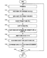
図2は、実施の形態1におけるバックライト制御方法を示すフローチャートである。
まず、映像入力端子101に入力された映像信号に基づいて、特徴量算出部102は、特徴量を算出する(S10)。
FIG. 2 is a flowchart showing a backlight control method according to the first embodiment.
First, based on the video signal input to the
次に、部分最大値検出部103は、各部分領域で部分特徴量最大値を検出する(S11)。
また、部分平均値算出部104は、各部分領域で部分特徴量平均値を算出する(S12)。
全体平均値算出部105は、全画面で特徴量平均値を算出する(S13)。
Next, the partial maximum
Further, the partial average
The overall
加重平均係数算出部106は、全体平均値算出部105で算出された全画面の特徴量平均値から加重平均係数を算出する(S14)。
そして、加重平均算出部は、加重平均係数算出部106で算出された加重平均係数を用いて、部分領域毎に、その部分特徴量最大値と、その部分特徴量平均値とを加重平均する(S15)。
The weighted average
Then, using the weighted average coefficient calculated by the weighted average
平均値算出部108は、加重平均算出部107で算出された加重平均値の平均値である基準平均値を算出する(S16)。
そして、比較部109は、加重平均算出部107から与えられた一つの部分領域の加重平均値と、平均値算出部108から与えられた基準平均値とを比較する。
部分制御値算出部111は、全体平均値算出部105で算出された特徴量平均値に基づいて全体制御値算出部110で算出された全体制御値を受け取る。そして、部分制御値算出部111は、比較部109での比較結果に応じて、全体制御値から各部分領域のバックライト制御値である部分制御値を算出する(S18)。
The average
Then, the
The partial control
そして、映像信号の入力が続く等、特に終了する必要がない場合(S19でYES)には、処理はステップS10に戻り、これらのステップが繰り返される。全てのステップは、一般的に映像信号の時系列的な入力に対し、繰り返し行われる。 Then, when it is not necessary to particularly terminate the process, such as continuing the input of the video signal (YES in S19), the process returns to step S10, and these steps are repeated. All steps are generally repeated for time-sequential input of the video signal.
具体的な数値を挙げて、計算方法を示したが、以下に、具体的な映像を例に、効果を説明する。
図3は、全体平均輝度が低い場合の映像例を示す概略図である。
図3に示されている映像170では、左上に月があり、右にビルがある。ビルの窓は、明るく光っている場合を想定している。簡単のため、背景は一様であるとする。
Although the calculation method is shown by giving specific numerical values, the effect will be described below by taking a specific image as an example.
FIG. 3 is a schematic view showing an example of an image when the overall average luminance is low.
In the
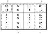
図4は、図3に示された映像170に含まれる部分領域毎の最大輝度と平均輝度とを示す概略図である。
図4に示されている上側の数字が最大輝度、下側の数字が平均輝度である。全体平均輝度は、簡単のため10とする。
図4に示されているように、左上の区域を区域A、右上のビルが一部分ある区域を区域B、右側のビルがある区域を区域C、背景の区域を区域Dとする。
FIG. 4 is a schematic view showing the maximum luminance and the average luminance for each partial area included in the
The upper numbers shown in FIG. 4 are the maximum brightness, and the lower numbers are the average brightness. The overall average luminance is 10 for simplicity.
As shown in FIG. 4, an upper left area is an area A, an upper right area is an area having a part of a building, an area B is an area having a building on the right side, and an area D is a background area.
全体平均輝度が10であるため、(1)式により、加重平均係数は、0.15となる。
そして、それぞれの区域に含まれる部分領域の加重平均輝度は、(2)式に基づいて、以下の(9)式から(12)式により求められる。
区域A: 15×0.15+90×(1−0.15)= 78.75 (9)
区域B: 10×0.15+80×(1−0.15)= 69.5 (10)
区域C: 20×0.15+80×(1−0.15)= 71 (11)
区域D: 5×0.15+ 5×(1−0.15)= 5 (12)
Since the overall average luminance is 10, the weighted average coefficient is 0.15 according to equation (1).
Then, the weighted average luminance of the partial region included in each area is obtained by the following equations (9) to (12) based on the equation (2).
Area A: 15 × 0.15 + 90 × (1-0.15) = 78.75 (9)
Area B: 10 × 0.15 + 80 × (1-0.15) = 69.5 (10)
Area C: 20 × 0.15 + 80 × (1-0.15) = 71 (11)
Area D: 5 × 0.15 + 5 × (1-0.15) = 5 (12)
この時、各区域に含まれる部分領域の加重平均輝度を有効映像領域全体で平均した基準平均値は、下記の(13)により、およそ27.5になる。
(78.75+69.5+71×2+5×8)÷12=27.5 (13)
At this time, a reference average value obtained by averaging the weighted average luminances of the partial areas included in each area over the entire effective image area is approximately 27.5 according to (13) below.
(78.75 + 69.5 + 71 × 2 + 5 × 8) ÷ 12 = 27.5 (13)
そして、比較部109で算出される各区域に含まれる部分領域の偏差は、(4)式に従って、下記の(14)式から(17)式により求められる。
区域A: 78.75−27.5=51.25 (14)
区域B: 69.5−27.5=42 (15)
区域C: 71−27.5=43.5 (16)
区域D: 5−27.5=−22.5 (17)
Then, the deviation of the partial region included in each area calculated by the
Area A: 78.75-27.5 = 51.25 (14)
Area B: 69.5-27.5 = 42 (15)
Area C: 71-27.5 = 43.5 (16)
Area D: 5-27.5 = -22.5 (17)
全体制御値算出部110は、全体平均輝度から、全体制御値を算出する。全体平均輝度が低い場合、全体制御値は小さくなる。この例では、全体平均輝度が10と低いため、(7)式により、全体制御値は25となる。
The overall control
次に、部分制御値算出部111は、(8)式に基づいて、下記の(18)式から(21)式により、各区域に含まれる部分領域の部分制御値を算出する。
区域A: 25+51.25×G (18)
区域B: 25+42×G (19)
区域C: 25+43.5×G (20)
区域D: 25−22.5×G (21)
Next, the partial control
Area A: 25 + 51.25 x G (18)
Area B: 25 + 42 × G (19)
Area C: 25 + 43.5 × G (20)
Area D: 25-22.5 x G (21)
例えば、G=1とすれば、(18)式〜(21)式により、区域Aに含まれる部分領域の部分制御値は76.25、区域Bに含まれる部分領域の部分制御値は67、区域Cに含まれる部分領域の部分制御値は68.5、区域Dに含まれる部分領域の部分制御値は2.5となる。
ここで、部分制御値には、最大値及び最小値が設定されており、部分制御値算出部111は、算出された部分制御値が最小値よりも小さい場合には、最小値を採用し、算出された部分制御部が最大値よりも大きい場合には、最大値を採用する。例えば、最小値は、0、5又は20に設定されている。最小値が0である場合には、算出された部分制御値が負の値となった場合は、設定された最小値が出力される。
For example, if G = 1, the partial control value of the partial area included in area A is 76.25, and the partial control value of the partial area included in area B is 67, according to equations (18) to (21). The partial control value of the partial region included in the area C is 68.5, and the partial control value of the partial region included in the area D is 2.5.
Here, maximum and minimum values are set as partial control values, and the partial control
このように、各区域での平均輝度にあまり差がなくても、各区域の部分制御値は、大きく異なる。このため、メリハリのあるバックライト制御を行うことができる。具体的には、月及びビルの窓が明るく輝いて見える。 Thus, even if there is not much difference in the average brightness in each area, the partial control value of each area is greatly different. For this reason, it is possible to perform backlight control with sharpening. Specifically, the windows of the moon and the building appear bright.
次に、全体平均輝度が高い場合の例を示す。
図5は、全体平均輝度が高い場合の映像例を示す概略図である。
図5に示されている映像171では、左上に太陽があり、右にビルがある。また、中央下部に木とその影がある。簡単のため、背景は一様であるとする。
Next, an example where the overall average luminance is high is shown.
FIG. 5 is a schematic view showing an example of an image when the overall average luminance is high.
In the
図6は、図5に示された映像171に含まれる部分領域毎の最大輝度と平均輝度とを示す概略図である。
図6に示されている上側の数字が最大輝度、下側の数字が平均輝度である。全体平均輝度は、簡単のため50とする。
図6に示されているように、左上の区域を区域A、右上のビルが一部分ある区域を区域B、右側のビルがある区域を区域C、木がある区域を区域域D、木の影がある区域を区域E、背景の区域を区域Fとする。
FIG. 6 is a schematic view showing the maximum luminance and the average luminance for each partial area included in the
The upper numbers shown in FIG. 6 are the maximum brightness, and the lower numbers are the average brightness. The overall average luminance is 50 for simplicity.
As shown in FIG. 6, the upper left area is an area A, the upper right area is an area with a part of a building area B, the area with a right building is an area C, an area with trees is an area D, a tree shadow The area where there is an area is called area E, and the area of the background is called area F.
全体平均輝度が50であるため、(1)式により、加重平均係数は、0.55となる。
そして、それぞれの区域に含まれる部分領域の加重平均輝度は、(2)式に基づいて、以下の(22)式から(27)式により求められる。
区域A: 70×0.55+100×(1−0.55)= 83.5 (22)
区域B: 55×0.55+80 ×(1−0.55)= 66.25 (23)
区域C: 60×0.55+80 ×(1−0.55)= 69 (24)
区域D: 40×0.55+50 ×(1−0.55)= 44.5 (25)
区域E: 20×0.55+50 ×(1−0.55)= 33.5 (26)
区域F: 50×0.55+50 ×(1−0.55)= 50 (27)
Since the overall average luminance is 50, the weighted average coefficient is 0.55 according to equation (1).
Then, the weighted average luminance of the partial region included in each area is obtained by the following equations (22) to (27) based on the equation (2).
Area A: 70 × 0.55 + 100 × (1-0.55) = 83.5 (22)
Area B: 55 × 0.55 + 80 × (1-0.55) = 66.25 (23)
Area C: 60 × 0.55 + 80 × (1-0.55) = 69 (24)
Area D: 40 × 0.55 + 50 × (1-0.55) = 44.5 (25)
Area E: 20 × 0.55 + 50 × (1-0.55) = 33.5 (26)
Section F: 50 × 0.55 + 50 × (1-0.55) = 50 (27)
この時、各区域に含まれる部分領域の加重平均輝度を有効映像領域全体で平均した平均値は、下記の(28)により、およそ55.5になる。
(83.5+66.25+69×2+44.5+33.5+50×6)÷12
=55.5 (28)
At this time, the average value obtained by averaging the weighted average luminance of the partial areas included in each area over the entire effective image area is approximately 55.5 according to the following (28).
(83.5 + 66.25 + 69 × 2 + 44.5 + 33.5 + 50 × 6) ÷ 12
= 55.5 (28)
そして、比較部109で算出される各区域に含まれる部分領域の偏差は、(4)式に従って、下記の(29)式〜(34)式により求められる。
区域A: 83.5 −55.5=28 (29)
区域B: 66.25−55.5=10.75 (30)
区域C: 69 −55.5=13.5 (31)
区域D: 44.5 −55.5=−11 (32)
区域E: 33.5 −55.5=−22 (33)
区域F: 50 −55.5=−5.5 (34)
Then, the deviation of the partial region included in each area calculated by the
Area A: 83.5-55.5 = 28 (29)
Area B: 66.25-55.5 = 10.75 (30)
Area C: 69-55.5 = 13.5 (31)
Area D: 44.5-55.5 = -11 (32)
Area E: 33.5-55.5 = -22 (33)
Area F: 50-55.5 =-5.5 (34)
全体制御値算出部110は、全体平均輝度から、全体制御値を算出する。全体平均輝度が高い場合、全体制御値は大きくなる。この例では、全体平均輝度が50と比較的高いため、(7)式により、全体制御値は100となる。
The overall control
次に、部分制御値算出部111は、(8)式に基づいて、下記の(35)式〜(40)式により、各区域に含まれる部分領域の部分制御値を算出する。
区域A 100+28×G (35)
区域B 100+10.75×G (36)
区域C 100+13.5×G (37)
区域D 100−11×G (38)
区域E 100−22×G (39)
区域F 100−5.5×G (40)
Next, the partial control
Area D 100-11 × G (38)
Area E 100-22 x G (39)
Area F 100-5.5 x G (40)
例えば、G=1とすれば、式(35)〜式(40)により、区域Aに含まれる部分領域の部分制御値は128、区域Bに含まれる部分領域の部分制御値は110.75、区域Cに含まれる部分領域の部分制御値は113.5、区域Dに含まれる部分領域の部分制御値は89、区域Eに含まれる部分領域の部分制御値は78、区域Fに含まれる部分領域の部分制御値は94.5となる。 For example, if G = 1, the partial control value of the partial area included in area A is 128, and the partial control value of the partial area included in area B is 110.75, according to equations (35) to (40). Partial control value of partial area included in area C is 113.5, partial control value of partial area included in area D is 89, partial control value of partial area included in area E is 78, part included in area F The partial control value of the area is 94.5.
ここで、区域Aは128、区域Bは110.75、区域Cは113.5となるが、部分制御値には最大値及び最小値が設定されているため、これらの区域に含まれる部分領域の部分制御値は、最大値(例えば、100、95又は80等)に設定される。例えば、最大値が80の場合は、区域A、区域B及び区域Cの他、区域D及び区域Fの部分制御値も80となる。 Here, although the area A is 128, the area B is 110.75, and the area C is 113.5, since the partial control values are set to the maximum value and the minimum value, the partial areas included in these areas The partial control value of is set to a maximum value (e.g., 100, 95 or 80). For example, when the maximum value is 80, in addition to the area A, the area B and the area C, the partial control values of the area D and the area F also become 80.
このように、各区域での平均輝度にあまり差がなくても、各区域の部分制御値は、大きく異なる。このため、メリハリのあるバックライト制御を行うことができる。具体的には、木の影が黒く引き締まり、コントラストが高くなり、高画質化が可能となる。 Thus, even if there is not much difference in the average brightness in each area, the partial control value of each area is greatly different. For this reason, it is possible to perform backlight control with sharpening. Specifically, the shadow of a tree is tightened black, the contrast is high, and high image quality can be achieved.
なお、最大輝度を検出する際には、意図しない信号(ノイズ)による影響を和らげるため、近隣の画素間で、ローパスフィルタ(LPF)を用いて、突出した最大値を抑制することができる。また、時間方向でもLPFを用いることで、例えば、それぞれの部分領域で、1画面前の最大輝度に現画面の最大輝度を一定の割合(この割合については設定可能)で加算することで、時間的に突出した最大値を抑制することができる。 In addition, when detecting the maximum luminance, since the influence of an unintended signal (noise) is mitigated, it is possible to suppress the projected maximum value using a low pass filter (LPF) between adjacent pixels. Also, by using the LPF even in the time direction, for example, in each partial region, the maximum luminance of the previous screen is added to the maximum luminance of the current screen at a constant ratio (this ratio can be set) It is possible to suppress the maximum value that has been projected.
以上の説明では、特徴量の例として輝度を用いたが、例えば、入力映像が赤、緑及び青の3原色であった場合は、輝度に準ずる値が簡易的な計算式で求められてもよい。入力映像が明るい時に大きくなる数値であれば、輝度に代えて用いることができる。
また、各画素で、画素毎に特定される値の最大値、例えば、赤、緑及び青の画素値の最大値を特徴量としても良い。例えば、赤、緑及び青の画素値の最大値を特徴量とした場合、赤いバラ等は、高い特徴量になり、特徴量を輝度とした時より、バックライトを明るく制御することができる。この場合には、色鮮やかな物を明るく表示したい表示装置等と組み合わせると、効果が期待できる。
In the above description, although luminance is used as an example of the feature amount, for example, when the input image is the three primary colors of red, green and blue, even if a value according to the luminance can be obtained by a simple calculation formula Good. If the input image is a numerical value that increases when it is bright, it can be used instead of the luminance.
In addition, the maximum value of the values specified for each pixel, for example, the maximum values of the pixel values of red, green and blue may be used as the feature amount in each pixel. For example, when the maximum value of pixel values of red, green and blue is used as a feature amount, red roses and the like become high feature amounts, and it is possible to control the backlight brighter than when the feature amount is luminance. In this case, an effect can be expected when combined with a display device or the like that wants to display a colorful object brightly.
以上では、加重平均係数の算出例として、(1)式を用いて算出しているが、加重平均係数の最大値は、1より小さい値であってもよい。また、加重平均係数の最小値が、例えば、0.5等と予め定められた値に決められていてもよい。
また、(1)式のように、加重平均係数の算出式は、必ずしも、全体平均輝度(ALLAVG)の1次式である必要はない。例えば、全体として特徴量の平均を重視したい場合、又は、特徴量の最大値を重視したい場合等、コンテンツ、ディスプレイの性能又はディスプレイの周辺環境により、適切な最大値、最小値及び計算式を用いることで、様々な調整が可能である。例えば、各部分領域において、特徴量の平均の差が小さいが特徴量の最大値に比較的大きな差があるとき、特徴量の最大値の差が小さいが特徴量の平均に比較的大きな差があるとき等に、各部分領域間のバックライトの輝度差が大きい方がよいか又は小さい方がよいかで、様々な調整が可能である。
In the above, although the weighted average coefficient is calculated using equation (1) as an example of calculation of the weighted average coefficient, the maximum value of the weighted average coefficient may be a value smaller than one. In addition, the minimum value of the weighted average coefficient may be determined to a predetermined value such as 0.5, for example.
Also, as in equation (1), the equation for calculating the weighted average coefficient does not necessarily have to be a linear expression of the overall average luminance (ALLAVG). For example, if it is desired to emphasize the average of feature quantities as a whole, or if it is desired to emphasize the maximum value of feature quantities, an appropriate maximum value, minimum value and calculation formula may be used according to content, display performance or display peripheral environment. Various adjustments are possible. For example, in each partial region, when the difference between the averages of the feature amounts is small but the maximum value of the feature amounts is relatively large, the difference between the maximum values of the feature amounts is small, but the average value of the feature amounts is relatively large. At some times, etc., various adjustments can be made depending on whether the difference in backlight luminance between the partial regions is preferably larger or smaller.
また、実施の形態1では、比較部109は、減算を行っているが、除算を行ってもよい。即ち、比較部109は、基準平均値に対する加重平均値の割合を求めてもよい。その場合は、部分制御値算出部111は、加算ではなく、乗算を行う。
In the first embodiment, the
実施の形態2.
図7は、実施の形態2に係る画像処理装置200の構成を概略的に示すブロック図である。
画像処理装置200は、映像入力端子101と、特徴量算出部102と、部分最大値検出部103と、部分平均値算出部104と、全体平均値算出部105と、加重平均係数算出部206と、加重平均算出部107と、平均値算出部108と、比較部109と、全体制御値算出部110と、部分制御値算出部111と、周辺部分平均値算出部213と、出力端子112とを備える。
実施の形態2に係る画像処理装置200は、周辺部分平均値算出部213及び加重平均係数算出部206を除いて、実施の形態1に係る画像処理装置100と同様に構成されている。以下では、主に、周辺部分平均値算出部213及び加重平均係数算出部206について説明する。実施の形態2では、加重平均係数を算出する際に用いられる平均値を算出する範囲が、部分領域毎に異なる範囲となっている。
Second Embodiment
FIG. 7 is a block diagram schematically showing the configuration of the
The
The
ここで、部分最大値検出部103、部分平均値算出部104、加重平均係数算出部206、加重平均算出部107、平均値算出部108、比較部109及び周辺部分平均値算出部213により、部分相対制御値算出部220が構成される。
また、特徴量算出部102、全体平均値算出部105、部分相対制御値算出部220、全体制御値算出部110及び部分制御値算出部111により、バックライト制御装置230が構成される。
Here, partial maximum
Further, a
周辺部分平均値算出部213は、部分最大値検出部103で特徴量最大値が検出された部分領域と同じ部分領域を含む予め定められた周辺部分の特徴量の平均値である周辺部分平均値を算出する。周辺部分は、例えば、それぞれの部分領域と、その周辺の8個の部分領域とを含む9個の部分領域であってもよい。また、周辺部分は、それぞれの部分領域を中心とする、水平方向に5個の部分領域と、垂直方向に3個の部分領域とに構成される15個の部分領域であってもよい。さらに、周辺部分は、それぞれの部分領域を中心とする、水平方向に7個の部分領域と、垂直方向に5個の部分領域とに構成される35個の部分領域であってもよい。
The peripheral part average
加重平均係数算出部206は、周辺部分平均値算出部213から与えられる周辺部分平均値から加重平均係数を算出する。
例えば、加重平均係数算出部206は、周辺部分平均値算出部213から与えられる周辺部分平均値である周辺部分平均輝度(PARTAVG)を用いて、下記の(41)式から、加重平均係数(CE)を算出する。
CE=PARTAVG×0.01+0.05 (41)
但し、加重平均係数(CE)の最大値は1である。
The weighted average coefficient calculation unit 206 calculates a weighted average coefficient from the peripheral partial average value given from the peripheral partial average
For example, the weighted average coefficient calculation unit 206 uses the peripheral partial average luminance (PARTAVG), which is the peripheral partial average value given from the peripheral partial
CE = PARTAVG × 0.01 + 0.05 (41)
However, the maximum value of the weighted average coefficient (CE) is 1.
以下に、具体的な映像を例に、効果を説明する。
図8は、バックライトの領域分割数が比較的多い場合の映像例を示す概略図である。
The effects will be described below by taking a specific video as an example.
FIG. 8 is a schematic view showing an example of an image when the number of area divisions of the backlight is relatively large.
図8に示されている映像272には、明るさの異なる様々な物が含まれている。
例えば、映像272に含まれている木の影に着目すると、木の影の領域の明るさは暗めに制御することが望まれる。映像全体の平均輝度が比較的高く、かつ、木の影の周辺の領域の平均輝度の方が映像全体の平均輝度より高い場合、映像全体の平均輝度により加重平均係数を算出するより、木の影の周辺部分の平均輝度から加重平均係数を算出した方が、最大輝度よりも平均輝度を重視する計算になる。このため、より望ましい明るさ制御が可能となる。これは、全体が暗い映像の場合でも同じことが言える。
The
For example, focusing on the shadow of a tree included in the
加重平均係数を算出するための平均輝度を計算するための最適な範囲は、人の目が一度に認識できる範囲等のように、都合のよい範囲設定が可能か否が関わるので、画面全体の大きさが大きく、バックライトの領域分割数が比較的多い場合に、このような周辺部分平均輝度による加重平均係数の算出方法に効果がある。 The optimum range for calculating the average luminance for calculating the weighted average coefficient depends on whether or not convenient range setting is possible, such as a range that can be recognized by one's eyes at a time. When the size is large and the number of area divisions of the backlight is relatively large, the method of calculating the weighted average coefficient by such peripheral partial average luminance is effective.
実施の形態3.
図9は、実施の形態3に係る画像処理装置300の構成を概略的に示すブロック図である。
画像処理装置300は、映像入力端子101と、特徴量算出部102と、部分相対制御値算出部120、220と、部分制御値算出部111と、出力端子112と、全体制御値入力端子314とを備える。
実施の形態3に係る画像処理装置300は、全体制御値入力端子314を除いて、実施の形態1に係る画像処理装置100又は実施の形態2に係る画像処理装置200と同様に構成されている。以下では、主に、全体制御値入力端子314について説明する。
Third Embodiment
FIG. 9 is a block diagram schematically showing the configuration of the
The
The
ここで、特徴量算出部102、部分相対制御値算出部120、220及び部分制御値算出部111により、バックライト制御装置330が構成される。
実施の形態3におけるバックライト制御装置330には、全体制御値が外部から入力される。
なお、部分相対制御値算出部120、220は、実施の形態1における部分相対制御値算出部120及び実施の形態2における部分相対制御値算出部220の何れか一方である。
Here, the
The entire control value is input from the outside to the
The partial relative control
全体制御値入力端子314は、全体制御値の入力を受け付ける。
実施の形態3における部分制御値算出部111は、部分相対制御値算出部120、220から与えられた値に設定値Gを乗算し、全体制御値入力端子314から与えられた全体制御値に加算する。
The overall control
The partial control
実施の形態3は、全面のバックライト制御機能はあるが部分領域毎に制御する機能がない回路(集積回路:IC等)に、バックライトを部分領域毎に制御する機能を付加する時に有効な構成である。 The third embodiment is effective when adding a function to control the backlight for each partial area to a circuit (integrated circuit: IC etc.) having a backlight control function on the entire surface but not having a function to control each partial area. It is a structure.
実施の形態4.
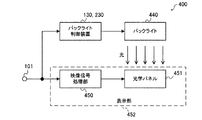
図10は、実施の形態4に係る画像表示装置としての画像処理装置400の構成を概略的に示すブロック図である。
画像処理装置400は、映像入力端子101と、バックライト制御装置130、230と、バックライト440と、映像信号処理部450と、光学パネル451とを備える。
実施の形態4における映像入力端子101は、実施の形態1と同様に構成されている。
実施の形態4におけるバックライト制御装置130、230は、実施の形態1におけるバックライト制御装置130及び実施の形態2におけるバックライト制御装置230の何れか一方である。
Fourth Embodiment
FIG. 10 is a block diagram schematically showing a configuration of an
The
The
The
バックライト440は、バックライト制御装置130、230からの部分制御値に基づいて、部分領域毎に光を発する。ここで、バックライト440は、複数の部分領域で明るさを制御することができる。
映像信号処理部450は、映像入力端子101に入力された映像信号に高画質化処理等を施して出力する。例えば、映像信号処理部450は、一般的な映像信号処理、例えば、ノイズ除去、輝度補正、色補正、輪郭補正又は超解像処理等を行う。
光学パネル451は、映像信号処理部450から入力された映像信号により、光の透過率を変化させる。光学パネル451は、例えば、液晶パネルである。
ここで、映像信号処理部450及び光学パネル451により、入力画像に基づいて画像を表示する表示部452が構成される。
The
The video
The
Here, the video
以上のような構成により、実施の形態4に係る画像処理装置400は、実施の形態1又は実施の形態2で説明したような画像を出力することができる。
With the above configuration, the
実施の形態5.
図11は、実施の形態5に係る画像表示装置としての画像処理装置500の構成を概略的に示すブロック図である。
画像処理装置500は、映像入力端子101と、全体制御値入力端子314と、バックライト制御装置330と、バックライト440と、映像信号処理部450と、光学パネル451とを備える。
実施の形態5における画像処理装置500は、全体制御値入力端子314及びバックライト制御装置330を除いて、実施の形態4に係る画像処理装置400と同様に構成されている。
FIG. 11 is a block diagram schematically showing a configuration of an
The
The
実施の形態5における全体制御値入力端子314は、実施の形態3における全体制御値入力端子314である。
実施の形態5におけるバックライト制御装置330は、実施の形態3におけるバックライト制御装置330である。
The general control
The
以上のような構成により、実施の形態5に係る画像処理装置500は、実施の形態3で説明したような画像を出力することができる。
With the configuration as described above, the
以上に記載されたバックライト制御装置130、230、330の一部又は全部は、例えば、図12(A)に示されているように、メモリ661と、メモリ661に格納されているプログラムを実行するCPU(Central Processing Unit)等のプロセッサ662とにより構成することができる。このようなプログラムは、ネットワークを通じて提供されてもよく、また、記録媒体に記録されて提供されてもよい。即ち、このようなプログラムを記録したコンピュータで読み取り可能な記憶媒体もまた本発明の一部を成す。
Some or all of the
また、バックライト制御装置130、230、330の一部又は全部は、例えば、図12(B)に示されているように、単一回路、復号回路、プログラム化したプロセッサ、並列プログラム化したプロセッサ、ASIC(Application Specific Integrated Circuits)又はFPGA(Field Programmable Gate Array)等の処理回路663で構成することもできる。
Also, some or all of the
以上の実施の形態によれば、バックライトの制御は連続して変化するため、バックライトの輝度は、なめらかに変化し、画質が劣化しない。 According to the above embodiment, since the control of the backlight changes continuously, the brightness of the backlight changes smoothly and the image quality does not deteriorate.
また、以上の実施の形態1によれば、映像全体の全体平均輝度によって、部分領域内の部分平均輝度と部分領域内の部分最大輝度が加重平均される。このため、例えば、全体に明るい画像では、部分領域内の部分平均輝度が重視され、部分領域間で、部分領域内の部分最大輝度の差が少なくなっても、メリハリのあるバックライト制御を行うことができる。また、全体に暗い画像では、部分領域内の部分最大輝度が重視され、部分領域内の一部に明るい部分がある場合でも、バックライトを明るく制御し、明るく輝く部分を好ましく表現することができる。 Further, according to the first embodiment, the partial average luminance in the partial area and the partial maximum luminance in the partial area are weighted-averaged by the entire average luminance of the entire video. Therefore, for example, in an overall bright image, emphasis is placed on partial average luminance in a partial area, and backlight control with sharpening is performed even if the difference in partial maximum luminance in a partial area decreases between partial areas. be able to. In the case of a dark image as a whole, the partial maximum brightness in the partial area is emphasized, and even if there is a bright part in a part of the partial area, the backlight can be controlled brightly to preferably express the bright part .
また、以上の実施の形態2によれば、対象となる部分領域とその周辺の部分領域を含む範囲の平均輝度によって、部分領域内の部分平均輝度と部分領域内の部分最大輝度とが加重平均される。このため、例えば、一定程度のエリアにまたがって暗いエリアがあり、その中の一部エリア内に明るい部分がある場合に、部分領域内の部分最大輝度が重視されることで、バックライトを明るく制御し、明るく輝く部分を好ましく表現することができる。 Further, according to the second embodiment described above, the partial average luminance in the partial area and the partial maximum luminance in the partial area are weighted averages by the average luminance of the range including the target partial area and the partial area around it. Be done. For this reason, for example, when there is a dark area across a certain degree of area and there is a bright part in a part of the area, the backlight is brightened by emphasizing the partial maximum luminance in the partial area. It is possible to control and preferably express bright and bright parts.
さらに、各部分領域内で、加重平均によって得られた値を全ての部分領域で平均した基準平均値と、各部分領域で加重平均によって得られた値とを比較し、全体のバックエリア制御値に加算するため、各部分領域のバックライト輝度の偏りの強さを簡単に制御でき、全体のバックライト制御と違和感なく融合することができる。 Furthermore, within each partial area, a reference average value obtained by averaging the values obtained by the weighted average in all partial areas is compared with the value obtained by the weighted average in each partial area, and the total back area control value Therefore, it is possible to easily control the intensity of the bias of the backlight luminance of each partial region, and it is possible to merge with the entire backlight control without a sense of discomfort.
100,200,300,400,500 画像処理装置、 101 映像入力端子、 102 特徴量算出部、 103 部分最大値検出部、 104 部分平均値算出部、 105 全体平均値算出部、 106,206 加重平均係数算出部、 107 加重平均算出部、 108 平均値算出部、 109 比較部、 110 全体制御値算出部、 111 部分制御値算出部、 112 出力端子、 213 周辺部分平均値算出部、 314 全体制御値入力端子、 120,220 部分相対制御値算出部、 130,230,330 バックライト制御装置、 440 バックライト、 450 映像信号処理部、 451 光学パネル、 452 表示部、 661 メモリ、 662 プロセッサ、 663 処理回路。
100, 200, 300, 400, 500 image processing apparatus, 101 video input terminal, 102 feature amount calculation unit, 103 partial maximum value detection unit, 104 partial average value calculation unit, 105 overall average value calculation unit, 106, 206 weighted average Coefficient calculation unit, 107 weighted average calculation unit, 108 average value calculation unit, 109 comparison unit, 110 whole control value calculation unit, 111 partial control value calculation unit, 112 output terminal, 213 peripheral partial average value calculation unit, 314 whole control
Claims (6)
前記入力画像に含まれる部分領域における前記特徴量の最大値である部分最大値を、前記入力画像に含まれる部分領域毎に検出する部分最大値検出部と、
前記部分領域における前記特徴量の平均値である部分平均値を、前記部分領域毎に算出する部分平均値算出部と、
予め定められた範囲における前記特徴量の平均値が大きいほど前記部分平均値の割合が高くなるように加重平均係数を算出する加重平均係数算出部と、
前記部分領域毎に、前記加重平均係数を用いて、前記部分最大値及び前記部分平均値の加重平均値を算出する加重平均算出部と、
前記加重平均値の平均値である基準平均値を算出する平均値算出部と、
前記部分領域毎に、前記加重平均値と、前記基準平均値とを比較するために、前記基準平均値を用いて前記加重平均値の偏差を求める比較部と、
バックライトの全体の明るさを示す全体制御値に、前記偏差に設定値を乗算した値を加算することで、前記設定値に応じて、前記比較部の比較結果に基づいて、前記部分領域毎に、前記加重平均値が前記基準平均値よりも大きいほど、前記バックライトの対応する部分が明るくなるように、又は、前記部分領域の明るさが同じとなるように、部分制御値を算出する部分制御値算出部と、を備えること
を特徴とするバックライト制御装置。 A feature amount calculation unit that calculates a feature amount for each pixel of the input image;
A partial maximum value detection unit that detects, for each partial region included in the input image, a partial maximum value that is a maximum value of the feature amount in a partial region included in the input image;
A partial average calculation unit configured to calculate, for each of the partial regions, a partial average value that is an average value of the feature amounts in the partial regions;
A weighted average coefficient calculation unit that calculates a weighted average coefficient such that the proportion of the partial average value increases as the average value of the feature amounts in a predetermined range increases;
A weighted average calculation unit configured to calculate a weighted average value of the partial maximum value and the partial average value using the weighted average coefficient for each of the partial regions;
An average value calculation unit that calculates a reference average value that is an average value of the weighted average values;
A comparison unit for determining the deviation of the weighted average value using the reference average value to compare the weighted average value with the reference average value for each partial region;
By adding a value obtained by multiplying the deviation to a setting value to an overall control value indicating the overall brightness of the backlight, each partial area is added based on the comparison result of the comparing unit according to the setting value. , the more the weighted average value is greater than the reference average value, wherein as the corresponding portion of the backlight becomes brighter, or the brightness of the partial region is to be the same, to calculate the partial control value backlight control device according to claim Rukoto and a partial control value calculation unit.
前記特徴量平均値に基づいて、前記全体制御値を算出する全体制御値算出部をさらに備えること
を特徴とする請求項1に記載のバックライト制御装置。 An overall average value calculation unit that calculates a feature amount average value that is an average value of the feature amounts in the entire input image;
The backlight control device according to claim 1 , further comprising: an overall control value calculation unit configured to calculate the overall control value based on the feature amount average value.
を特徴とする請求項1又は2に記載のバックライト制御装置。 The feature amount backlight control device according to claim 1 or 2, characterized in that the luminance.
を特徴とする請求項1から3の何れか一項に記載のバックライト制御装置。 The backlight control device according to any one of claims 1 to 3 , wherein the feature amount is a maximum value of values specified for each pixel.
入力画像の画素毎に特徴量を算出する特徴量算出部と、
前記入力画像に含まれる部分領域における前記特徴量の最大値である部分最大値を、前記入力画像に含まれる部分領域毎に検出する部分最大値検出部と、
前記部分領域における前記特徴量の平均値である部分平均値を、前記部分領域毎に算出する部分平均値算出部と、
予め定められた範囲における前記特徴量の平均値が大きいほど前記部分平均値の割合が高くなるように加重平均係数を算出する加重平均係数算出部と、
前記部分領域毎に、前記加重平均係数を用いて、前記部分最大値及び前記部分平均値の加重平均値を算出する加重平均算出部と、
前記加重平均値の平均値である基準平均値を算出する平均値算出部と、
前記部分領域毎に、前記加重平均値と、前記基準平均値とを比較するために、前記基準平均値を用いて前記加重平均値の偏差を求める比較部と、
バックライトの全体の明るさを示す全体制御値に、前記偏差に設定値を乗算した値を加算することで、前記設定値に応じて、前記比較部の比較結果に基づいて、前記部分領域毎に、前記加重平均値が前記基準平均値よりも大きいほど、前記バックライトの対応する部分が明るくなるように、又は、前記部分領域の明るさが同じとなるように、部分制御値を算出する部分制御値算出部と、
前記入力画像に基づいて画像を表示する表示部と、を備え、
前記バックライトは、前記部分制御値に基づいて、部分毎に明るさを制御すること
を特徴とする画像表示装置。 With backlight
A feature amount calculation unit that calculates a feature amount for each pixel of the input image;
A partial maximum value detection unit that detects, for each partial region included in the input image, a partial maximum value that is a maximum value of the feature amount in a partial region included in the input image;
A partial average calculation unit configured to calculate, for each of the partial regions, a partial average value that is an average value of the feature amounts in the partial regions;
A weighted average coefficient calculation unit that calculates a weighted average coefficient such that the proportion of the partial average value increases as the average value of the feature amounts in a predetermined range increases;
A weighted average calculation unit configured to calculate a weighted average value of the partial maximum value and the partial average value using the weighted average coefficient for each of the partial regions;
An average value calculation unit that calculates a reference average value that is an average value of the weighted average values;
A comparison unit for determining the deviation of the weighted average value using the reference average value to compare the weighted average value with the reference average value for each partial region;
By adding a value obtained by multiplying the deviation to a setting value to an overall control value indicating the overall brightness of the backlight, each partial area is added based on the comparison result of the comparing unit according to the setting value. , the more the weighted average value is greater than the reference average value, wherein as the corresponding portion of the backlight becomes brighter, or the brightness of the partial region is to be the same, to calculate the partial control value A partial control value calculation unit,
A display unit for displaying an image based on the input image;
Before SL backlight, based on the partial control values, the image display apparatus and controls the brightness for each part.
前記入力画像に含まれる部分領域における前記特徴量の最大値である部分最大値を、前記入力画像に含まれる部分領域毎に検出し、
前記部分領域における前記特徴量の平均値である部分平均値を、前記部分領域毎に算出し、
予め定められた範囲における前記特徴量の平均値が大きいほど前記部分平均値の割合が高くなるように加重平均係数を算出し、
前記部分領域毎に、前記加重平均係数を用いて、前記部分最大値及び前記部分平均値の加重平均値を算出し、
前記加重平均値の平均値である基準平均値を算出し、
前記部分領域毎に、前記基準平均値を用いて前記加重平均値の偏差を求めることで、前記加重平均値と、前記基準平均値とを比較して、前記部分領域毎に、バックライトの全体の明るさを示す全体制御値に、前記偏差に設定値を乗算した値を加算することで、前記設定値に応じて、前記加重平均値が前記基準平均値よりも大きいほど、前記バックライトの対応する部分が明るくなるように、又は、前記部分領域の明るさが同じとなるように、部分制御値を算出すること
を特徴とするバックライト制御方法。 Calculate the feature amount for each pixel of the input image,
A partial maximum value which is a maximum value of the feature amount in a partial region included in the input image is detected for each partial region included in the input image;
Calculating a partial average value, which is an average value of the feature amounts in the partial regions, for each of the partial regions,
The weighted average coefficient is calculated such that the proportion of the partial average value increases as the average value of the feature amounts in a predetermined range increases.
Calculating a weighted average value of the partial maximum value and the partial average value using the weighted average coefficient for each of the partial regions;
Calculate a reference average value which is an average value of the weighted average values,
By calculating the deviation of the weighted average value using the reference average value for each of the partial areas, the weighted average value is compared with the reference average value to obtain an overall backlight for each of the partial areas. the overall control value indicating the brightness of, by adding the value obtained by multiplying the set value to the deviation, according to the setting value, the higher the weighted mean value is greater than the reference average value, of the backlight Calculating a partial control value such that the corresponding part is bright or the partial area has the same brightness .
Priority Applications (1)
| Application Number | Priority Date | Filing Date | Title |
|---|---|---|---|
| JP2015239019A JP6505007B2 (en) | 2015-12-08 | 2015-12-08 | BACKLIGHT CONTROL DEVICE, IMAGE DISPLAY DEVICE, AND BACKLIGHT CONTROL METHOD |
Applications Claiming Priority (1)
| Application Number | Priority Date | Filing Date | Title |
|---|---|---|---|
| JP2015239019A JP6505007B2 (en) | 2015-12-08 | 2015-12-08 | BACKLIGHT CONTROL DEVICE, IMAGE DISPLAY DEVICE, AND BACKLIGHT CONTROL METHOD |
Publications (3)
| Publication Number | Publication Date |
|---|---|
| JP2017106991A JP2017106991A (en) | 2017-06-15 |
| JP2017106991A5 JP2017106991A5 (en) | 2017-11-16 |
| JP6505007B2 true JP6505007B2 (en) | 2019-04-24 |
Family
ID=59060769
Family Applications (1)
| Application Number | Title | Priority Date | Filing Date |
|---|---|---|---|
| JP2015239019A Expired - Fee Related JP6505007B2 (en) | 2015-12-08 | 2015-12-08 | BACKLIGHT CONTROL DEVICE, IMAGE DISPLAY DEVICE, AND BACKLIGHT CONTROL METHOD |
Country Status (1)
| Country | Link |
|---|---|
| JP (1) | JP6505007B2 (en) |
Cited By (1)
| Publication number | Priority date | Publication date | Assignee | Title |
|---|---|---|---|---|
| JP2018156813A (en) * | 2017-03-17 | 2018-10-04 | 三菱電機株式会社 | Backlight controller, image display device and backlight control method |
Families Citing this family (2)
| Publication number | Priority date | Publication date | Assignee | Title |
|---|---|---|---|---|
| KR101988555B1 (en) * | 2017-12-05 | 2019-06-12 | 충북대학교 산학협력단 | Simultaneous localization and mapping system using illumination invariant image, and method for mapping pointcloud thereof |
| WO2023050189A1 (en) * | 2021-09-29 | 2023-04-06 | 京东方科技集团股份有限公司 | Brightness adjustment method and adjustment system, and display device |
Family Cites Families (4)
| Publication number | Priority date | Publication date | Assignee | Title |
|---|---|---|---|---|
| JP2011242604A (en) * | 2010-05-18 | 2011-12-01 | Sony Corp | Liquid crystal display apparatus |
| WO2012090358A1 (en) * | 2010-12-28 | 2012-07-05 | パナソニック株式会社 | Video signal processing device |
| JP5323272B2 (en) * | 2011-02-09 | 2013-10-23 | 三菱電機株式会社 | LIGHT EMITTING CONTROL DEVICE AND METHOD, LIGHT EMITTING DEVICE, IMAGE DISPLAY DEVICE, PROGRAM, AND RECORDING MEDIUM |
| JP2014137390A (en) * | 2013-01-15 | 2014-07-28 | Canon Inc | Display device and control method therefor |
-
2015
- 2015-12-08 JP JP2015239019A patent/JP6505007B2/en not_active Expired - Fee Related
Cited By (1)
| Publication number | Priority date | Publication date | Assignee | Title |
|---|---|---|---|---|
| JP2018156813A (en) * | 2017-03-17 | 2018-10-04 | 三菱電機株式会社 | Backlight controller, image display device and backlight control method |
Also Published As
| Publication number | Publication date |
|---|---|
| JP2017106991A (en) | 2017-06-15 |
Similar Documents
| Publication | Publication Date | Title |
|---|---|---|
| CN109064979B (en) | Image display processing method and device, display device and storage medium | |
| US11270657B2 (en) | Driving method, driving apparatus, display device and computer readable medium | |
| JP5595516B2 (en) | Method and system for backlight control using statistical attributes of image data blocks | |
| US10810950B2 (en) | Light source control device, display device, and image processing device | |
| CN102726036B (en) | Enhancement of images for display on liquid crystal displays | |
| TWI439996B (en) | Method for adjusting a backlight of a display device and device thereof | |
| US20120075353A1 (en) | System and Method for Providing Control Data for Dynamically Adjusting Lighting and Adjusting Video Pixel Data for a Display to Substantially Maintain Image Display Quality While Reducing Power Consumption | |
| US20080240557A1 (en) | Methods and apparatuses for restoring color and enhancing electronic images | |
| US20160027354A1 (en) | Display unevenness correction apparatus, display apparatus, method for correcting display unevenness, an method for manufacturing the display apparatus | |
| CN105161064A (en) | Liquid crystal display brightness control method and device and liquid crystal display device | |
| CN105513559B (en) | A kind of image processing method and display device | |
| US10192495B2 (en) | Display apparatus with lighting device, control method for display apparatus, and storage medium | |
| CN101281731A (en) | Liquid crystal display method | |
| US11393416B2 (en) | Method and device for backlight control, electronic device, and computer readable storage medium | |
| US20110025725A1 (en) | Backlight unit and control method for the same | |
| KR20120117887A (en) | Methods and systems for reducing power consumption in dual modulation displays | |
| JP6505007B2 (en) | BACKLIGHT CONTROL DEVICE, IMAGE DISPLAY DEVICE, AND BACKLIGHT CONTROL METHOD | |
| US20080297467A1 (en) | Method for backlight modulation and image processing | |
| JP2015007739A (en) | Display divice and control method thereof | |
| JP6265710B2 (en) | Image processing apparatus, computer program, and image processing method | |
| KR20070114163A (en) | Method and/or apparatus to improve the visual perception of an image displayed on a screen | |
| JP6395232B2 (en) | Image display device and light source dimming method | |
| JP6108238B2 (en) | Control circuit and display device thereof | |
| US9886644B2 (en) | Image processing method and device | |
| KR20090003080A (en) | Display apparatus and method of adjusting brightness for the same |
Legal Events
| Date | Code | Title | Description |
|---|---|---|---|
| A521 | Request for written amendment filed |
Free format text: JAPANESE INTERMEDIATE CODE: A523 Effective date: 20171004 |
|
| A621 | Written request for application examination |
Free format text: JAPANESE INTERMEDIATE CODE: A621 Effective date: 20171004 |
|
| A977 | Report on retrieval |
Free format text: JAPANESE INTERMEDIATE CODE: A971007 Effective date: 20180706 |
|
| A131 | Notification of reasons for refusal |
Free format text: JAPANESE INTERMEDIATE CODE: A131 Effective date: 20180807 |
|
| A521 | Request for written amendment filed |
Free format text: JAPANESE INTERMEDIATE CODE: A523 Effective date: 20180927 |
|
| TRDD | Decision of grant or rejection written | ||
| A01 | Written decision to grant a patent or to grant a registration (utility model) |
Free format text: JAPANESE INTERMEDIATE CODE: A01 Effective date: 20190226 |
|
| A61 | First payment of annual fees (during grant procedure) |
Free format text: JAPANESE INTERMEDIATE CODE: A61 Effective date: 20190326 |
|
| R150 | Certificate of patent or registration of utility model |
Ref document number: 6505007 Country of ref document: JP Free format text: JAPANESE INTERMEDIATE CODE: R150 |
|
| R250 | Receipt of annual fees |
Free format text: JAPANESE INTERMEDIATE CODE: R250 |
|
| LAPS | Cancellation because of no payment of annual fees |