US9534681B2 - Wave gear device having tapered flexible external gear - Google Patents
Wave gear device having tapered flexible external gear Download PDFInfo
- Publication number
- US9534681B2 US9534681B2 US14/348,298 US201114348298A US9534681B2 US 9534681 B2 US9534681 B2 US 9534681B2 US 201114348298 A US201114348298 A US 201114348298A US 9534681 B2 US9534681 B2 US 9534681B2
- Authority
- US
- United States
- Prior art keywords
- section
- tooth
- tooth profile
- external
- teeth
- Prior art date
- Legal status (The legal status is an assumption and is not a legal conclusion. Google has not performed a legal analysis and makes no representation as to the accuracy of the status listed.)
- Active, expires
Links
Images


Classifications
-
- F—MECHANICAL ENGINEERING; LIGHTING; HEATING; WEAPONS; BLASTING
- F16—ENGINEERING ELEMENTS AND UNITS; GENERAL MEASURES FOR PRODUCING AND MAINTAINING EFFECTIVE FUNCTIONING OF MACHINES OR INSTALLATIONS; THERMAL INSULATION IN GENERAL
- F16H—GEARING
- F16H49/00—Other gearings
- F16H49/001—Wave gearings, e.g. harmonic drive transmissions
-
- F—MECHANICAL ENGINEERING; LIGHTING; HEATING; WEAPONS; BLASTING
- F16—ENGINEERING ELEMENTS AND UNITS; GENERAL MEASURES FOR PRODUCING AND MAINTAINING EFFECTIVE FUNCTIONING OF MACHINES OR INSTALLATIONS; THERMAL INSULATION IN GENERAL
- F16H—GEARING
- F16H55/00—Elements with teeth or friction surfaces for conveying motion; Worms, pulleys or sheaves for gearing mechanisms
- F16H55/02—Toothed members; Worms
- F16H55/08—Profiling
- F16H55/0833—Flexible toothed member, e.g. harmonic drive
-
- F—MECHANICAL ENGINEERING; LIGHTING; HEATING; WEAPONS; BLASTING
- F16—ENGINEERING ELEMENTS AND UNITS; GENERAL MEASURES FOR PRODUCING AND MAINTAINING EFFECTIVE FUNCTIONING OF MACHINES OR INSTALLATIONS; THERMAL INSULATION IN GENERAL
- F16H—GEARING
- F16H49/00—Other gearings
- F16H49/001—Wave gearings, e.g. harmonic drive transmissions
- F16H2049/003—Features of the flexsplines therefor
-
- Y—GENERAL TAGGING OF NEW TECHNOLOGICAL DEVELOPMENTS; GENERAL TAGGING OF CROSS-SECTIONAL TECHNOLOGIES SPANNING OVER SEVERAL SECTIONS OF THE IPC; TECHNICAL SUBJECTS COVERED BY FORMER USPC CROSS-REFERENCE ART COLLECTIONS [XRACs] AND DIGESTS
- Y10—TECHNICAL SUBJECTS COVERED BY FORMER USPC
- Y10T—TECHNICAL SUBJECTS COVERED BY FORMER US CLASSIFICATION
- Y10T74/00—Machine element or mechanism
- Y10T74/19—Gearing
- Y10T74/19642—Directly cooperating gears
- Y10T74/19647—Parallel axes or shafts
Definitions
- the present invention relates to a wave gear device having a tapered flexible external gear furnished with a tooth profile capable of continuous meshing over a wide range in the tooth trace direction.
- the present invention relates to a wave gear device having a tapered flexible external gear, whereby maximization of transmission load torque is possible through optimization of the rim thickness established in the flexible external gear.
- Patent Document 1 Since the invention of the wave gear device by C. W. Musser (Patent Document 1) up to the present day, inventions for devices of various types have been conceived by its originator, as well as by numerous researchers, including the present inventor. Even limiting the discussion to inventions relating to the tooth profile, numerous different types have been proposed. For example, in Patent Document 2, the present inventor proposed using an involute tooth profile as a basic tooth profile; and in Patent Documents 3 and 4 proposed a tooth profile design method employing a procedure for approximating, by means of a rack, meshing of the teeth of a rigid internal gear and a flexible external gear of a wave gear device, to derive an addendum tooth profile that affords contact of the two gears over a wide area.
- a wave gear device has a ring-shaped rigid internal gear, a flexible external gear disposed coaxially to the inside thereof, and a wave generator fitting inside thereof.
- the flexible external gear is provided with a flexible cylindrical barrel portion, a diaphragm radially extending from the rear end of this cylindrical barrel portion, and external teeth formed on the outside peripheral face section of the cylindrical barrel portion at the front end opening side thereof.
- the flexible external gear is flexed into ellipsoidal shape by the wave generator, and meshes with the rigid internal gear at both ends in the major axis direction of the ellipse.
- the external teeth of the flexible external gear flexed into ellipsoidal shape have an increasing amount of flexure, proportional to the distance from the diaphragm, from the diaphragm side towards the front end opening along the tooth trace direction thereof.
- sections of the tooth portion of the flexible external gear undergo repeated flexure in radial directions in association with rotation of the wave generator.
- sufficient consideration has not been given to a rational method for establishing a tooth profile in a manner that takes into consideration such flexural action (coning) of the flexible external gear by the wave generator.
- Patent Document 5 the present inventor proposed a wave gear device provided with a tooth profile by which continuous meshing is possible, with consideration given to coning of the teeth.
- a first homothetic curve BC is derived by scaling down, by a ratio ⁇ ( ⁇ 1) while employing a point B as the homothetic center, a curve segment extending from a point A of an apical portion to the point B in the next bottom portion in a movement locus of a standard deflection obtained in the principal cross section, and this first homothetic curve BC is adopted as the basic tooth profile for the addendum of the rigid internal gear.
- a second homothetic curve is derived by scaling, by a ratio (1 ⁇ )/ ⁇ while employing an end point C of the first homothetic curve BC as the homothetic center, of a curve obtained by 180 degree rotation of the first homothetic curve BC about a center at the point C, and this second homothetic curve is adopted as the basic tooth profile for the addendum of the flexible external gear.
- a transposition is applied to tooth profile sections to both sides, in the tooth trace direction, from the principal cross section in the tooth profile of the flexible external gear, doing so in such a way that both negative deflecting-side movement loci obtained in axis-perpendicular cross sections flexed to a negative deflection state (flexural coefficient ⁇ 1) to the diaphragm side from the principal cross section in the external teeth of the flexible external gear, and positive deflection-side movement loci obtained in axis-perpendicular cross sections flexed to a positive deflection state (flexural coefficient ⁇ >1) to the opening side from the principal cross section, describe curves that contact the bottom part of the standard-deflecting movement locus in the principal cross section.
- the resultant flexible external gear is a tapered flexible gear having an addendum circle of progressively smaller diameter from the opening side towards the diaphragm side in the tooth trace direction.
- the tooth profiles of both gears and the external tooth rim thickness are established according to the procedure of (1) to (6) below.
- a modified Goodman diagram is employed to establish optimal root rim thickness at the opening end location in the tooth trace direction of the external teeth of the flexible external gear.
- a modified Goodman diagram is employed to establish (on the basis of the optimal root rim thickness at the opening end location) the root rim thickness at locations other than the opening end in the tooth trace direction of the external teeth.
- a wave gear device capable of continuous meshing, provided with a tapered flexible external gear with which continuous meshing is achieved over a wide range in the principal cross section of an opening end location of the external teeth, as well as achieving meshing over a wide range in the tooth trace direction, wherein the root rim thickness of the flexible external gear, which had been given no consideration whatsoever in the prior art, can be established at optimal thickness at each location in the tooth trace direction, so as to be commensurate with the transmission load torque. Therefore, according to the present invention, it is possible to greatly improve the transmission load torque of a flexible external gear of a wave gear device, as compared with the prior art.
- FIG. 1 is a schematic front view of a typical wave gear device
- FIG. 2 is a descriptive diagram showing conditions of flexure of a flexible external gear, (a) showing a state prior to deformation, (b) showing a state in a cross section including the major axis of a flexible external gear when deformed to ellipsoidal shape, and (c) showing a state in a cross section including the minor axis of a flexible external gear when deformed to ellipsoidal shape;
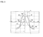
- FIG. 3 is a descriptive diagram showing an example of the tooth profiles of both gears in an axis-perpendicular cross section (principal cross section) of the opening end of external teeth;
- FIG. 4 is a descriptive diagram showing a tooth profile shape in the tooth trace direction of external teeth to which tooth profile shifting has been applied;
- FIG. 5 is a descriptive diagram showing movement loci of external teeth with respect to internal teeth, obtained through rack approximation of the relative motion of a flexible external gear and a rigid internal gear, in axis-perpendicular cross sections at an opening end location, a medial location, and an inner end location in the tooth trace direction of the external teeth of a flexible external gear;
- FIG. 6 is a descriptive diagram showing a procedure for deriving respective tooth profiles for both gears, from movement loci in a principal cross section (standard-deflecting cross section) of the external teeth of a flexible external gear;
- FIG. 7 is a descriptive diagram showing a procedure employing a modified Goodman diagram to determine the root rim thickness of a flexible external gear
- FIG. 8 is a descriptive diagram showing three movement loci, for a principal cross section of the tooth profile of a flexible external gear to which tooth profile shifting has been applied, and for cross sections to the front and back thereof.
- FIG. 9A is a descriptive diagram showing conditions of meshing in a cross section (standard-deflecting cross section) at an opening end location of external teeth in the tooth trace direction of the tooth profile of both gears;
- FIG. 9B is a descriptive diagram showing conditions of meshing in a cross section (negative-deflecting cross section) at a medial location of external teeth in the tooth trace direction of the tooth profile of both gears;
- FIG. 9C is a descriptive diagram showing the conditions of meshing in a cross section (negative-deflecting cross section) at an inner end location of external teeth in the tooth trace direction of the tooth profile of both gears.
- FIG. 1 is a front view of a wave gear device to which the present invention is directed.
- the cross sectional views in FIG. 2 show, in axis-including cross section, a condition in which the opening of the flexible external gear thereof is flexed into ellipsoidal shape, wherein FIG. 2( a ) shows a state prior to deformation, FIG. 2( b ) shows a cross section including the major axis of an ellipsoidal curve subsequent to deformation, and FIG. 2( c ) shows a cross section including the minor axis of an ellipsoidal curve subsequent to deformation, respectively.
- the solid lines indicate a flexible external gear of cup shape, and the broken lines show a flexible external gear of silk hat shape.
- the wave gear device 1 has a ring-shaped rigid internal gear 2 , a flexible external gear 3 disposed to the inside thereof, and a wave generator 4 of ellipsoidal contours fitting inside thereof.
- the rigid internal gear 2 and the flexible external gear 3 are both spur gears of module m.
- the difference in number of teeth between the two gears is 2n (n is a positive integer), with the rigid internal gear 2 having the greater number.
- the flexible external gear 3 is flexed into ellipsoidal shape by the wave generator 4 of ellipsoidal contours, and meshes with the rigid internal gear 2 in sections at either end of the ellipsoidal shape in the major axis L 1 direction.
- the flexible external gear 3 is provided with a flexible cylindrical barrel part 31 , a diaphragm 32 continuing on from the rear end 31 b thereof and spreading out in a radial direction, a boss 33 continuing on from the diaphragm 32 , and external teeth 34 formed on an outside peripheral surface section at an opening 31 a side of the cylindrical barrel part 31 .
- the cylindrical barrel part 31 Due to the wave generator 4 of ellipsoidal contours fitting within an inside peripheral surface section of the external tooth formation section of the cylindrical barrel part 31 , the cylindrical barrel part 31 experiences a progressively increasing amount of flexure towards the outside or towards the inside in a radial direction, towards the opening end 31 a from a rear end 31 b on the diaphragm side. As shown in FIG. 2( b ) , in a cross section that includes the major axis L 1 of the ellipsoidal shape, the amount of flexure towards the outside progressively increases in proportion to the distance from the rear end 31 b to the opening end 31 a ; and as shown in FIG.
- the amount of flexure towards the inside progressively increases in proportion to the distance from the rear end 31 b to the opening end 31 a . Consequently, the external teeth 34 formed on the outside peripheral surface section at the opening end 31 a side likewise experience varying amounts of flexure in axis-perpendicular cross sections in the tooth trace direction thereof. Specifically, the amount of flexure progressively increases, in a manner proportional to the distance from the rear end 31 b , from the location of the inner end 34 b on the diaphragm side towards the location of the opening end 34 a on the opening side in the tooth trace direction of the external teeth 34 .
- FIG. 3 is a descriptive diagram showing an example of the tooth profiles of both gears 2 , 3 ; and FIG. 4 is a descriptive diagram showing a tooth profile contour shape in the tooth trace direction of the flexible external gear 3 .
- the tooth profile shape of the external teeth 34 shown in FIG. 3 is that at the location of the opening end 34 a (principal cross section) thereof, and the tooth profile shape in a section extending from the opening end 34 a to the inner end 34 b of the external teeth 34 is a shifted tooth profile shape obtained by applying minus tooth profile shifting to the tooth profile shape shown in FIG. 3 , in the manner discussed below. As a result, as shown in FIG.
- the flexible external gear 3 is a tapered flexible external gear in which the diameter of the addendum circle becomes progressively smaller from the opening end 34 a towards the inner end 34 b along the tooth trace direction.
- the tooth profile shape of the inner teeth 24 is unchanging along the entire tooth trace direction, and is established to have the tooth profile shape shown in FIG. 3 .
- the tooth profile shape at the opening end 34 a (principal cross section) of the external teeth 34 is defined by an external tooth addendum tooth profile section 41 of convex curving shape, an external tooth linear tooth profile section 42 continuous therewith, an external tooth dedendum tooth profile section 43 of concave curving shape continuous therewith, and an external tooth root section 44 continuous therewith.
- the tooth profile shape of the internal teeth 24 is defined by an internal tooth addendum tooth profile section 51 of convex curving shape, an internal tooth linear tooth profile section 52 continuous therewith, an internal tooth dedendum tooth profile section 53 of concave curving shape continuous therewith, and an internal tooth root section 54 continuous therewith.
- FIG. 5 is a diagram showing movement loci of the external teeth 34 of the flexible external gear 3 with respect to the internal teeth 24 of the rigid internal gear 2 , obtained through rack approximation of the relative motion of the two gears 2 , 3 .
- the x axis is the translation direction of the rack
- the y axis shows a direction perpendicular thereto.
- the amount of flexure by the external tooth 34 in question at the major axis location L 1 in an ellipsoidal rim neutral line with respect to the rim neutral line prior to flexure of the external tooth 34 in question into ellipsoidal shape is 2 ⁇ mn, where ⁇ is the flexural coefficient.
- the origin of the y axis in FIG. 5 is the average position of amplitude of the movement loci.
- the principal cross section serving as the foundation for formation of the tooth profile of the two gears 2 , 3 is an axis-perpendicular cross section at the location of the opening end 34 a in the tooth trace direction of the external teeth 34 of the flexible external gear 3 .
- the negative deflecting movement locus M 2 is a locus obtained in an axis-perpendicular cross section at a medial location in the tooth trace direction of the external teeth 34
- the negative deflecting movement locus M 3 is a locus obtained at the location of the inner end 34 b in the tooth trace direction of the external teeth 34 .
- FIG. 6 is a descriptive diagram showing a utilization range of the standard deflecting movement locus M 1 , employed in forming the tooth profiles of the external teeth 34 and the inner teeth 24 .
- the parameter ⁇ of the standard deflecting movement locus M 1 of the principal cross section has a range from ⁇ (point B: the bottom portion of the movement locus) to 0 (point A: the apical portion of the movement locus), and with point B as the homothetic center, the standard deflecting movement locus M 1 undergoes homothetic transformation by a ratio ⁇ ( ⁇ 1), to obtain a first homothetic curve BC.
- the first homothetic curve BC is adopted as the tooth profile curve employed for defining the addendum tooth profile of the rigid internal gear 2 .
- the first homothetic curve BC is then rotated by 180 degrees about the end point C of the first homothetic curve BC, to obtain a curve B′C.
- a second homothetic curve AC is obtained through transformation of this curve B′C at a ratio (1 ⁇ )/ ⁇ at a homothetic center at the end point C.
- the second homothetic curve AC is adopted as the tooth profile curve employed for defining the addendum tooth profile of the flexible external gear 3 .
- the tooth profile curve AC for defining the addendum tooth profile is employed in forming an external tooth tooth profile in the principal cross section (an axis-perpendicular cross section of the opening end 34 a ) of the external teeth 34 in the following manner.
- a straight line L is drawn to intersect, at a pressure angle ⁇ , the tooth profile curve AC for defining the addendum tooth profile of the flexible external gear 3 , and a curve segment AD lying between the end point A of the tooth profile curve AC and an intersection point D with the straight line L is derived.
- the tooth profile curve in question is employed to form the external tooth addendum tooth profile section 41 .
- the external tooth linear tooth profile section 42 is defined by a line segment of the straight line L extending from the intersection point D.
- the external tooth deddendum tooth profile section 43 is defined by a predetermined convex curve connecting between the external tooth linear tooth profile section 42 and the external tooth root section 44 which is defined by a predetermined external tooth root curve, doing so in such a way as to ensure predetermined radial clearance of the external tooth linear tooth profile section 42 with respect to the internal teeth 24 .
- the tooth profile curve BC employed for defining the addendum tooth profile is employed to form the tooth profile of the internal teeth 24 .
- a straight line L is drawn to intersect, at a pressure angle ⁇ , the tooth profile curve BC for defining the addendum tooth profile of the rigid internal gear 2 , and a curve segment BE lying between the end point B of the tooth profile curve BC and an intersection point E with the straight line L is derived. Adopting this curve segment BE as the tooth profile curve defining a normal addendum tooth profile, the tooth profile curve in question is employed to form the internal tooth addendum tooth profile section 51 .
- the internal tooth linear tooth profile section 52 is defined by a line segment of the straight line L extending from the intersection point E.
- the internal tooth deddendum tooth profile section 53 is defined by a predetermined convex curve connecting the internal tooth linear tooth profile section 52 and the internal tooth root section 54 which is defined by a predetermined external tooth root curve, doing so in such a way as to ensure predetermined radial clearance of the internal tooth linear tooth profile section 52 with respect to the external teeth 34 .
- the tooth profile sections 43 , 44 , 53 , 54 of the deddendums of the two gears do not participate in meshing. Consequently, these dedendum tooth profile sections 43 , 44 , 53 , 54 can be designed freely, provided that there is no interference with the respective corresponding addendum tooth profile sections 51 , 52 , 41 , 42 .
- tooth profile shapes are formed at locations of principal cross sections (axis-perpendicular cross sections of the opening end 34 a of the external teeth 34 ) in both of the gears 2 , 3 shown in FIG. 3 .
- the pressure angle of the linear tooth profile ⁇ is 9 degrees. From the standpoint of machining of the gears, it is preferable to avoid sections in which the pressure angle of the addendum tooth profile is close to zero, and to connect the linear tooth profiles to the deddendum tooth profiles from points of a pressure angle of close to 6 degrees to 10 degrees.
- the negative deflecting movement loci M 2 , M 3 interfere with the non-deflecting movement locus M 1 , and for as long as this persists, continuous intermeshing of the addendum tooth profiles, such as that taking place in the case of the principal cross section, cannot be sustained.
- a shifted tooth profile in which a tooth profile shifting is applied to the tooth profile of the principal cross section (the axis-perpendicular cross section of the opening end 34 a ) is adopted as the external tooth tooth profile of axis-perpendicular cross sections in a section extending from the opening end 34 a to the inner end 34 b in the external teeth 34 .
- the shifted tooth profile shapes are obtained by applying minus tooth profile shifting to the external-tooth tooth profile of the opening end 34 a , doing in such a way that movement loci obtained through rack approximation of the external teeth 34 with respect to the internal teeth 24 in axis-perpendicular cross sections from the opening end 34 a to the inner end 34 b contact the bottom portion B of the movement locus M 1 obtained at the opening end 34 a constituting the principal cross section location. In so doing, proper meshing in at least localized fashion can be ensured on all cross sections in the tooth trace direction of the external teeth 34 .
- an amount of addendum modification mnh is established according to the flexural coefficient ⁇ at each of the axis-perpendicular cross section locations, doing so in such a way that the movement locus in each axis-perpendicular cross section contacts the bottom part B of the movement locus M 1 at the opening end 34 a .
- t 1 root rim thickness in principal cross section (axis-perpendicular cross section at the opening end).
- FIG. 7 shows the procedure of the present invention in which a so-called modified Goodman diagram is employed to determine the root rim thickness of a flexible external gear, and amounts of addendum modification for the teeth.
- ⁇ b is the tensile stress associated with bending of the root rim surface on the major axis in association with deformation of the flexible external gear 3 to ellipsoidal shape
- ⁇ b is defined by the following expression, taken from a basic formula of material mechanics.
- ⁇ b 3 Et /( RD )
- ⁇ n T /( DLt )
- L tooth width of flexible external gear
- a straight line is drawn connecting a point A (the vertical coordinate of which is ⁇ A ) at which the substantial fatigue limit of alternating stress of the steel constituting the material of the flexible external gear 3 is plotted on the vertical axis, and a point B (the horizontal coordinate of which is ⁇ B ) at which the center of yield stress and tensile strength of the steel is plotted on the horizontal axis, to create a so-called modified Goodman diagram.
- the triangular area bounded by this straight line, the horizontal axis, and the vertical axis is the permissible range of points produced by plotting the average stress of the root rim surface of the flexible external gear 3 on the horizontal axis, and the stress amplitude thereof on the vertical axis.
- a point P is derived by plotting, on the vertical axis, of the stress amplitude ( ⁇ b + ⁇ n /2) appearing at the root rim surface in the principal cross section (the axis-perpendicular cross section at the opening end 34 a ) arising due to rotation of the wave generator 4 , and plotting, on the horizontal axis, of the average stress ⁇ n /2.
- this point P it is necessary for this point P to be included within the aforedescribed triangular area.
- the transmission load torque T transmitted by the flexible external gear 3 is proportional to the product of the root rim thickness t and the tensile stress ⁇ n .
- the root rim thickness t is proportional to the tensile stress ⁇ b in association with bending. Consequently, the torque T of the flexible external gear is proportional to the product of the tensile stress ⁇ b and the tensile stress ⁇ n .
- ⁇ b is represented by a line segment PQ, where Q designates the intersection point of a straight line parallel to the vertical axis and passing through point P, and a straight line forming a 45 degree angle to the horizontal axis and passing through the origin. From the above, the torque T is proportional to the area of an oblong shape bounded by straight lines parallel to the horizontal axis and passing respectively through point P and point Q to the vertical axis, and the line segment PQ.
- the root rim thickness t 1 at the location of the opening end 34 a in the tooth trace direction of the external teeth 34 is ⁇ t 1 . Consequently, when the root rim thickness t 1 at the opening end 34 a is set to the optimal rim thickness t m in the aforedescribed manner, the root rim thickness t in each of axis-perpendicular cross sections taken from the opening end 34 a to the inner end 34 b of the external teeth 34 is set to ⁇ t m .
- the rim thickness of the flexible external gear is determined in such a fashion as to take progressively smaller values, in such a way that points corresponding to root rim thickness of axis-perpendicular cross sections lying in the tooth trace direction from the opening end 34 a to the inner end 34 b of the external teeth 34 are plotted to the right side of the midpoint M in the modified Goodman diagram.
- the coordinate points representing stress amplitude and average stress on the modified Goodman diagram it is necessary for the coordinate points representing stress amplitude and average stress on the modified Goodman diagram to lie within the permissible range mentioned earlier.
- the condition in question is met, and the coordinate points of the modified Goodman diagram representing the stress state of the flexible external gear 3 lie in the triangular area constituting the permissible range in the diagram in question.
- the root rim thickness of axis-perpendicular cross sections from the opening end 34 a to the inner end 34 b when the root rim thickness of the opening end 34 a of the flexible external gear has been assigned the optimal value t m , in order to sustain meshing of the tooth profiles along the tooth trace, the root rim thickness is set to ⁇ t m , which is equivalent to applying tooth profile shifting of a coefficient 1 ⁇ ( ⁇ 1) to the teeth, doing so in such a way that the bottom portions of the movement loci of the external teeth 34 of the flexible external gear 3 to the internal teeth 24 of the rigid internal gear 2 in each of the axis-perpendicular cross sections are made congruent.
- the tensile stress of the rim at any location increases in the manner ⁇ nm / ⁇ , with respect to the tensile stress ⁇ nm of the opening end 34 a due to torque.
- bending stress ⁇ b arising on the major axis in any cross section of the flexible external gear is proportional to the product of the rim thickness ⁇ t m and the amount of flexure w.
- FIG. 8 is a graph showing movement loci of external teeth on axis-perpendicular cross sections at the opening end 34 a (principal cross section), and at a medial location and at the inner end 34 b in the tooth trace direction, in the external teeth 34 for which the tooth profile has been established in the aforedescribed manner.
- the movement loci M 2a , M 3a of the shifted tooth profiles at the medial location and at the inner end 34 b contact the movement locus M 1 at the opening end 34 a in the bottom portion B, the shapes of the loci being mutually homothetic, with the exception of portions of the apical portions.
- FIG. 9A to FIG. 9C are descriptive diagrams showing, through rack approximation, the condition of meshing of external teeth and internal teeth for which tooth profiles have been established in the aforedescribed manner.
- FIG. 9A shows that obtained at the opening end location of the external teeth
- FIG. 9B that at a medial location in the tooth trace direction of the external teeth
- FIG. 9C that at the inner end location of the external teeth.
- the movement loci at each location in the tooth trace direction of the external teeth have good congruence in sections leading to the bottom portions thereof, whereby it may be appreciated that a state of meshing of the external teeth and the internal teeth is obtained over the entirety of the tooth trace.
Landscapes
- Engineering & Computer Science (AREA)
- General Engineering & Computer Science (AREA)
- Mechanical Engineering (AREA)
- Retarders (AREA)
- Gears, Cams (AREA)
Abstract
Description
- [Patent Document 1] U.S. Pat. No. 2,906,143
- [Patent Document 2] JP-B 45-41171
- [Patent Document 3] JP-A 63-115943
- [Patent Document 4] JP-A 64-79448
- [Patent Document 5] WO 2010/070712
x=0.5 mn(θ−κ sin θ)
y=κmn cos θ
x=0.5(θ−κ sin θ)
y=κ cos θ
x Ca=0.5{(1−λ)π+λ(θ−sin θ)}
y Ca=λ(1+cos θ)} (0≦θ≦π)
x Fa=0.5(1−λ)(π−θ+sin θ)}
y Fa=(1−λ)(1+cos θ)} (0≦θ≦π)
(Tooth Profile Shape of Principal Cross Section of External Teeth)
h=κ−1
t=κt 1
σb=3Et/(RD)
-
- t: root rim thickness
- R: reduction ratio
- D: diameter of rim neutral circle prior to deformation
σn =T/(DLt)
((σb+σn)−(−σb))/2=σb+σn/2
((σb+σn)+(−σb))/2=σn/2,
σb=σA/2
σn=σAσB/(σA+σB)
t 1 =t m=σA RD/(6E)
σb=κ2σbm=κ2σA/2.
From the equation for a straight line, the vertical coordinate corresponding to the horizontal coordinate of average stress σnm/κ/2 on the modified Goodman diagram is:
−(σA/σB)/σnm/2/κ+σA
Here, employing the relationship σbm=σA/2, in the axis-perpendicular cross section of the opening
(σB−σnm/2)(σA/σB)=σbm+σnm/2=σA/2+σnm/2
the following result is obtained.
σnm=σAσB/(σA+σB)
and this value is positive with respect to the range of actual values of κ (in the present example, from 1 to 0.7), thereby showing that the coordinate values with respect to the rim thickness κt lie within the permissible range.
(State of Meshing of Teeth)
Claims (4)
Applications Claiming Priority (1)
| Application Number | Priority Date | Filing Date | Title |
|---|---|---|---|
| PCT/JP2011/005521 WO2013046274A1 (en) | 2011-09-29 | 2011-09-29 | Wave gear device having tapered flexible external gear |
Publications (2)
| Publication Number | Publication Date |
|---|---|
| US20140251048A1 US20140251048A1 (en) | 2014-09-11 |
| US9534681B2 true US9534681B2 (en) | 2017-01-03 |
Family
ID=47994397
Family Applications (1)
| Application Number | Title | Priority Date | Filing Date |
|---|---|---|---|
| US14/348,298 Active 2032-10-19 US9534681B2 (en) | 2011-09-29 | 2011-09-29 | Wave gear device having tapered flexible external gear |
Country Status (5)
| Country | Link |
|---|---|
| US (1) | US9534681B2 (en) |
| JP (1) | JP5774713B2 (en) |
| CN (1) | CN103827542B (en) |
| DE (1) | DE112011105695T5 (en) |
| WO (1) | WO2013046274A1 (en) |
Cited By (7)
| Publication number | Priority date | Publication date | Assignee | Title |
|---|---|---|---|---|
| US10253862B2 (en) * | 2014-07-23 | 2019-04-09 | Harmonic Drive Systems Inc. | Dual-type strain wave gearing |
| US10760663B2 (en) * | 2014-06-16 | 2020-09-01 | Hiwin Technologies Corp. | Method of making strain wave gearing |
| US20220290752A1 (en) * | 2019-09-27 | 2022-09-15 | Harmonic Drive Systems Inc. | Flat strain wave gearing |
| US11786112B2 (en) | 2020-04-30 | 2023-10-17 | Ambu A/S | Endoscope control system |
| US11828356B2 (en) | 2020-10-30 | 2023-11-28 | Harmonic Drive Systems Inc. | Strain wave gearing provided with three-dimensional tooth profile |
| US12215769B2 (en) | 2023-02-13 | 2025-02-04 | Hamilton Sundstrand Corporation | Harmonic drive with flex spline end clamps |
| US12533009B2 (en) | 2020-04-30 | 2026-01-27 | Ambu A/S | Steering assembly for an endoscope, in particular for a single use endoscope |
Families Citing this family (17)
| Publication number | Priority date | Publication date | Assignee | Title |
|---|---|---|---|---|
| JP6221892B2 (en) * | 2014-03-27 | 2017-11-01 | アイシン精機株式会社 | Flexure meshing gear unit |
| JP6017066B2 (en) * | 2014-07-11 | 2016-10-26 | 株式会社ハーモニック・ドライブ・システムズ | Wave gear device having continuous contact tooth profile formed using arc tooth profile |
| JP6218692B2 (en) * | 2014-07-23 | 2017-10-25 | 株式会社ハーモニック・ドライブ・システムズ | Dual type wave gear device |
| WO2016194239A1 (en) * | 2015-06-02 | 2016-12-08 | 株式会社ハーモニック・ドライブ・システムズ | Strain wave gearing device with compound meshing that involves congruity of tooth surfaces |
| WO2017094195A1 (en) * | 2015-12-04 | 2017-06-08 | 株式会社ハーモニック・ドライブ・システムズ | 2-stress separating strain wave gearing device |
| JP6522791B2 (en) * | 2016-01-15 | 2019-05-29 | 株式会社ハーモニック・ドライブ・システムズ | Wave gear device of two stress pure separation |
| DE102016205748B3 (en) * | 2016-04-07 | 2017-07-20 | Schaeffler Technologies AG & Co. KG | actuating mechanism |
| JP6830736B2 (en) * | 2017-06-05 | 2021-02-17 | 株式会社ハーモニック・ドライブ・システムズ | Strain wave gearing with pure separation of two stresses |
| JP7188388B2 (en) * | 2017-08-23 | 2022-12-13 | 日本電産株式会社 | Decelerator |
| CN111201389B (en) * | 2017-10-19 | 2023-04-28 | 谐波传动系统有限公司 | Wave gear device with 3-dimensional meshing tooth profile |
| JP7168187B2 (en) * | 2018-02-22 | 2022-11-09 | 日本電産シンポ株式会社 | Flexible external gear and strain wave gearing having the same |
| JP6886415B2 (en) * | 2018-02-23 | 2021-06-16 | 住友重機械工業株式会社 | Gear device series, how to build a series of gear devices, and how to manufacture a group of gear devices |
| EP3795858A4 (en) * | 2018-05-14 | 2021-10-27 | Harmonic Drive Systems Inc. | WAVE GEAR DEVICE |
| US11732791B2 (en) * | 2020-01-08 | 2023-08-22 | Harmonic Drive System Inc. | Strain wave gearing |
| JP7530267B2 (en) * | 2020-10-16 | 2024-08-07 | 美的集団股▲フン▼有限公司 | Wave gear device and actuator |
| KR102573210B1 (en) | 2020-10-30 | 2023-08-30 | 가부시키가이샤 하모닉 드라이브 시스템즈 | Wave gear device with 3-dimensional teeth |
| CN114263708B (en) * | 2021-12-31 | 2024-02-06 | 浙江如川谐波传动科技有限公司 | Harmonic reducer |
Citations (17)
| Publication number | Priority date | Publication date | Assignee | Title |
|---|---|---|---|---|
| US2906143A (en) | 1955-03-21 | 1959-09-29 | United Shoe Machinery Corp | Strain wave gearing |
| JPS63115943A (en) | 1986-11-05 | 1988-05-20 | Haamonitsuku Drive Syst:Kk | Flexiblly meshing type gear device |
| JPS6479448A (en) | 1987-09-21 | 1989-03-24 | Harmonic Drive Systems | Deflection engagement type gear device |
| US5918508A (en) * | 1995-12-15 | 1999-07-06 | Harmonic Drive Systems, Inc. | Strain wave gearing having a non-interfering wide mesh range tooth profile |
| US6167783B1 (en) * | 1997-11-28 | 2001-01-02 | Harmonic Drive Systems, Inc. | Flexible meshing type gearing having three-dimensional, non-interactive wide-area intermeshing tooth profile |
| JP2001234988A (en) | 2000-02-22 | 2001-08-31 | Harmonic Drive Technologies-Teijin Seiki Boston Inc | Harmonic drive bearing structure |
| US20070180947A1 (en) | 2006-02-09 | 2007-08-09 | Harmonic Drive Systems Inc. | Wave gear drive with continuous meshing, high ratcheting torque tooth profile |
| WO2010023710A1 (en) | 2008-08-29 | 2010-03-04 | 株式会社ハーモニック・ドライブ・システムズ | Harmonic drive gear device having positive shift meshing compound tooth profile |
| WO2010070712A1 (en) | 2008-12-18 | 2010-06-24 | 株式会社ハーモニック・ドライブ・システムズ | Wave gear device having three-dimensionally contactable shifted tooth profile |
| US20100212446A1 (en) * | 2009-02-20 | 2010-08-26 | Harmonic Drive Systems Inc. | Wave gear device |
| US20100319484A1 (en) * | 2009-06-23 | 2010-12-23 | Harmonic Drive Systems Inc. | Wave Gear Device |
| JP2011144916A (en) | 2010-01-18 | 2011-07-28 | Harmonic Drive Systems Inc | Wave gear device having three-dimensionally contacting positive shifted tooth profile |
| US20120285283A1 (en) * | 2011-05-09 | 2012-11-15 | Harmonic Drive Systems Inc. | Wave gear device having three-dimensional continuous contact tooth profile |
| US20120304791A1 (en) * | 2011-06-01 | 2012-12-06 | Harmonic Drive Systems Inc. | Wave gear device provided with tapered flexible externally toothed gear |
| US20130081496A1 (en) * | 2011-02-04 | 2013-04-04 | Harmonic Drive Systems Inc. | Wave gear device having three-dimensional contacting involute positive deflection tooth profile |
| US20140224050A1 (en) * | 2013-02-11 | 2014-08-14 | California Institute Of Technology | Systems and methods for implementing bulk metallic glass-based strain wave gears and strain wave gear components |
| US20140345406A1 (en) * | 2012-01-10 | 2014-11-27 | Harmonic Drive Systems Inc. | Strain wave gearing with involute positive deflection tooth profile taking rim thickness into consideration |
Family Cites Families (2)
| Publication number | Priority date | Publication date | Assignee | Title |
|---|---|---|---|---|
| JP4132113B2 (en) * | 1996-11-27 | 2008-08-13 | 株式会社ハーモニック・ドライブ・システムズ | Flexure meshing gear unit |
| JP4999475B2 (en) * | 2007-01-24 | 2012-08-15 | 株式会社ハーモニック・ドライブ・システムズ | Flat wave gear device |
-
2011
- 2011-09-29 CN CN201180073828.4A patent/CN103827542B/en active Active
- 2011-09-29 US US14/348,298 patent/US9534681B2/en active Active
- 2011-09-29 WO PCT/JP2011/005521 patent/WO2013046274A1/en not_active Ceased
- 2011-09-29 DE DE112011105695.8T patent/DE112011105695T5/en active Pending
- 2011-09-29 JP JP2013535638A patent/JP5774713B2/en active Active
Patent Citations (20)
| Publication number | Priority date | Publication date | Assignee | Title |
|---|---|---|---|---|
| US2906143A (en) | 1955-03-21 | 1959-09-29 | United Shoe Machinery Corp | Strain wave gearing |
| JPS63115943A (en) | 1986-11-05 | 1988-05-20 | Haamonitsuku Drive Syst:Kk | Flexiblly meshing type gear device |
| JPS6479448A (en) | 1987-09-21 | 1989-03-24 | Harmonic Drive Systems | Deflection engagement type gear device |
| US5918508A (en) * | 1995-12-15 | 1999-07-06 | Harmonic Drive Systems, Inc. | Strain wave gearing having a non-interfering wide mesh range tooth profile |
| US6167783B1 (en) * | 1997-11-28 | 2001-01-02 | Harmonic Drive Systems, Inc. | Flexible meshing type gearing having three-dimensional, non-interactive wide-area intermeshing tooth profile |
| JP2001234988A (en) | 2000-02-22 | 2001-08-31 | Harmonic Drive Technologies-Teijin Seiki Boston Inc | Harmonic drive bearing structure |
| US20070180947A1 (en) | 2006-02-09 | 2007-08-09 | Harmonic Drive Systems Inc. | Wave gear drive with continuous meshing, high ratcheting torque tooth profile |
| JP2007211907A (en) | 2006-02-09 | 2007-08-23 | Harmonic Drive Syst Ind Co Ltd | Wave gear device having continuous meshing high ratcheting torque tooth profile |
| US7694607B2 (en) * | 2006-02-09 | 2010-04-13 | Harmonic Drive Systems Inc. | Wave gear drive with continuous meshing, high ratcheting torque tooth profile |
| WO2010023710A1 (en) | 2008-08-29 | 2010-03-04 | 株式会社ハーモニック・ドライブ・システムズ | Harmonic drive gear device having positive shift meshing compound tooth profile |
| WO2010070712A1 (en) | 2008-12-18 | 2010-06-24 | 株式会社ハーモニック・ドライブ・システムズ | Wave gear device having three-dimensionally contactable shifted tooth profile |
| US20110237382A1 (en) * | 2008-12-18 | 2011-09-29 | Harmonic Drive Systems Inc. | Wave gear device having three-dimensionally contactable shifted tooth profile |
| US20100212446A1 (en) * | 2009-02-20 | 2010-08-26 | Harmonic Drive Systems Inc. | Wave gear device |
| US20100319484A1 (en) * | 2009-06-23 | 2010-12-23 | Harmonic Drive Systems Inc. | Wave Gear Device |
| JP2011144916A (en) | 2010-01-18 | 2011-07-28 | Harmonic Drive Systems Inc | Wave gear device having three-dimensionally contacting positive shifted tooth profile |
| US20130081496A1 (en) * | 2011-02-04 | 2013-04-04 | Harmonic Drive Systems Inc. | Wave gear device having three-dimensional contacting involute positive deflection tooth profile |
| US20120285283A1 (en) * | 2011-05-09 | 2012-11-15 | Harmonic Drive Systems Inc. | Wave gear device having three-dimensional continuous contact tooth profile |
| US20120304791A1 (en) * | 2011-06-01 | 2012-12-06 | Harmonic Drive Systems Inc. | Wave gear device provided with tapered flexible externally toothed gear |
| US20140345406A1 (en) * | 2012-01-10 | 2014-11-27 | Harmonic Drive Systems Inc. | Strain wave gearing with involute positive deflection tooth profile taking rim thickness into consideration |
| US20140224050A1 (en) * | 2013-02-11 | 2014-08-14 | California Institute Of Technology | Systems and methods for implementing bulk metallic glass-based strain wave gears and strain wave gear components |
Non-Patent Citations (1)
| Title |
|---|
| International Search Report (PCT/ISA/210) mailed on Dec. 13, 2011, by the Japanese Patent Office as the International Searching Authority for International Application No. PCT/JP2011/005521. |
Cited By (11)
| Publication number | Priority date | Publication date | Assignee | Title |
|---|---|---|---|---|
| US10760663B2 (en) * | 2014-06-16 | 2020-09-01 | Hiwin Technologies Corp. | Method of making strain wave gearing |
| US10253862B2 (en) * | 2014-07-23 | 2019-04-09 | Harmonic Drive Systems Inc. | Dual-type strain wave gearing |
| US20220290752A1 (en) * | 2019-09-27 | 2022-09-15 | Harmonic Drive Systems Inc. | Flat strain wave gearing |
| US11841071B2 (en) * | 2019-09-27 | 2023-12-12 | Harmonic Drive Systems Inc. | Flat strain wave gearing |
| US11786112B2 (en) | 2020-04-30 | 2023-10-17 | Ambu A/S | Endoscope control system |
| US12011146B2 (en) | 2020-04-30 | 2024-06-18 | Ambu A/S | Method of assembly of an endoscope control system |
| US12396626B2 (en) | 2020-04-30 | 2025-08-26 | Ambu A/S | Method of assembly of an endoscope control system |
| US12402782B2 (en) | 2020-04-30 | 2025-09-02 | Ambu A/S | Endoscope control system |
| US12533009B2 (en) | 2020-04-30 | 2026-01-27 | Ambu A/S | Steering assembly for an endoscope, in particular for a single use endoscope |
| US11828356B2 (en) | 2020-10-30 | 2023-11-28 | Harmonic Drive Systems Inc. | Strain wave gearing provided with three-dimensional tooth profile |
| US12215769B2 (en) | 2023-02-13 | 2025-02-04 | Hamilton Sundstrand Corporation | Harmonic drive with flex spline end clamps |
Also Published As
| Publication number | Publication date |
|---|---|
| JPWO2013046274A1 (en) | 2015-03-26 |
| US20140251048A1 (en) | 2014-09-11 |
| WO2013046274A1 (en) | 2013-04-04 |
| DE112011105695T5 (en) | 2014-07-17 |
| CN103827542A (en) | 2014-05-28 |
| CN103827542B (en) | 2016-09-21 |
| JP5774713B2 (en) | 2015-09-09 |
Similar Documents
| Publication | Publication Date | Title |
|---|---|---|
| US9534681B2 (en) | Wave gear device having tapered flexible external gear | |
| JP5913378B2 (en) | Wave gear device having involute positive deviation tooth profile considering rim thickness | |
| US9903459B2 (en) | Strain wave gearing having continuous-contact tooth profile formed using arcuate tooth profile | |
| US8776638B2 (en) | Wave gear device having three-dimensionally contactable shifted tooth profile | |
| EP3306132B1 (en) | Strain wave gearing device with compound meshing that involves congruity of tooth surfaces | |
| JP5456941B1 (en) | Wave gear device having a three-dimensional contact tooth profile | |
| US20130081496A1 (en) | Wave gear device having three-dimensional contacting involute positive deflection tooth profile | |
| TWI638105B (en) | Harmonic gear device with negative offset tooth profile with 2 degree contact | |
| WO1997022818A1 (en) | Deflection mesh type gear having non-interference wide-range engaging tooth profile | |
| JP2005098479A (en) | Wave gear device having wide area three-dimensional meshing tooth profile | |
| US10883589B2 (en) | Two stress-separation strain wave gearing | |
| US10174825B2 (en) | Passing-type-meshing negative-deflection strain wave gearing | |
| US20100317483A1 (en) | High performance differential | |
| JP7203275B2 (en) | Strain wave gearing with three-dimensional tooth profile | |
| JPH05172196A (en) | Forming method for three-dimensional non-shifting tooth profile of flexible meshing type gearing | |
| JP2009156461A (en) | Tooth profile setting method capable of meshing non-positive deviation maximum in flat wave gear device |
Legal Events
| Date | Code | Title | Description |
|---|---|---|---|
| AS | Assignment |
Owner name: HARMONIC DRIVE SYSTEMS INC., JAPAN Free format text: ASSIGNMENT OF ASSIGNORS INTEREST;ASSIGNOR:ISHIKAWA, SHOICHI;REEL/FRAME:032552/0723 Effective date: 20120105 |
|
| FEPP | Fee payment procedure |
Free format text: PAYOR NUMBER ASSIGNED (ORIGINAL EVENT CODE: ASPN); ENTITY STATUS OF PATENT OWNER: LARGE ENTITY |
|
| STCF | Information on status: patent grant |
Free format text: PATENTED CASE |
|
| MAFP | Maintenance fee payment |
Free format text: PAYMENT OF MAINTENANCE FEE, 4TH YEAR, LARGE ENTITY (ORIGINAL EVENT CODE: M1551); ENTITY STATUS OF PATENT OWNER: LARGE ENTITY Year of fee payment: 4 |
|
| MAFP | Maintenance fee payment |
Free format text: PAYMENT OF MAINTENANCE FEE, 8TH YEAR, LARGE ENTITY (ORIGINAL EVENT CODE: M1552); ENTITY STATUS OF PATENT OWNER: LARGE ENTITY Year of fee payment: 8 |