US9533496B2 - Apparatus for ejecting liquids, ejection detection apparatus, and ejection detector - Google Patents
Apparatus for ejecting liquids, ejection detection apparatus, and ejection detector Download PDFInfo
- Publication number
- US9533496B2 US9533496B2 US15/046,573 US201615046573A US9533496B2 US 9533496 B2 US9533496 B2 US 9533496B2 US 201615046573 A US201615046573 A US 201615046573A US 9533496 B2 US9533496 B2 US 9533496B2
- Authority
- US
- United States
- Prior art keywords
- liquids
- receiver
- face
- ejection
- electrode
- Prior art date
- Legal status (The legal status is an assumption and is not a legal conclusion. Google has not performed a legal analysis and makes no representation as to the accuracy of the status listed.)
- Expired - Fee Related
Links
- 239000007788 liquid Substances 0.000 title claims abstract description 213
- 238000001514 detection method Methods 0.000 title claims description 42
- 230000008859 change Effects 0.000 claims abstract description 13
- 230000007246 mechanism Effects 0.000 description 29
- 230000000052 comparative effect Effects 0.000 description 8
- 230000008531 maintenance mechanism Effects 0.000 description 8
- 239000002699 waste material Substances 0.000 description 7
- 238000012423 maintenance Methods 0.000 description 6
- 238000011084 recovery Methods 0.000 description 6
- 230000000694 effects Effects 0.000 description 5
- 238000010586 diagram Methods 0.000 description 4
- 239000000463 material Substances 0.000 description 4
- 238000005259 measurement Methods 0.000 description 4
- 229910052758 niobium Inorganic materials 0.000 description 4
- PXHVJJICTQNCMI-UHFFFAOYSA-N Nickel Chemical compound [Ni] PXHVJJICTQNCMI-UHFFFAOYSA-N 0.000 description 3
- KDLHZDBZIXYQEI-UHFFFAOYSA-N Palladium Chemical compound [Pd] KDLHZDBZIXYQEI-UHFFFAOYSA-N 0.000 description 3
- 230000005856 abnormality Effects 0.000 description 3
- 230000003321 amplification Effects 0.000 description 3
- 239000003292 glue Substances 0.000 description 3
- 238000000034 method Methods 0.000 description 3
- 238000003199 nucleic acid amplification method Methods 0.000 description 3
- 238000007493 shaping process Methods 0.000 description 3
- 238000007599 discharging Methods 0.000 description 2
- 238000009413 insulation Methods 0.000 description 2
- 229910052751 metal Inorganic materials 0.000 description 2
- 239000002184 metal Substances 0.000 description 2
- 239000004033 plastic Substances 0.000 description 2
- 230000008569 process Effects 0.000 description 2
- 229910000881 Cu alloy Inorganic materials 0.000 description 1
- 230000002159 abnormal effect Effects 0.000 description 1
- 230000002776 aggregation Effects 0.000 description 1
- 238000004220 aggregation Methods 0.000 description 1
- 238000004458 analytical method Methods 0.000 description 1
- 238000013459 approach Methods 0.000 description 1
- 230000008901 benefit Effects 0.000 description 1
- 239000011230 binding agent Substances 0.000 description 1
- 230000005540 biological transmission Effects 0.000 description 1
- 230000015572 biosynthetic process Effects 0.000 description 1
- 239000000919 ceramic Substances 0.000 description 1
- 238000006243 chemical reaction Methods 0.000 description 1
- 238000004140 cleaning Methods 0.000 description 1
- 239000011248 coating agent Substances 0.000 description 1
- 238000000576 coating method Methods 0.000 description 1
- 239000003086 colorant Substances 0.000 description 1
- 230000007423 decrease Effects 0.000 description 1
- 239000000284 extract Substances 0.000 description 1
- 239000004744 fabric Substances 0.000 description 1
- 239000000835 fiber Substances 0.000 description 1
- 239000011521 glass Substances 0.000 description 1
- 230000003179 granulation Effects 0.000 description 1
- 238000005469 granulation Methods 0.000 description 1
- 230000005484 gravity Effects 0.000 description 1
- 230000010365 information processing Effects 0.000 description 1
- 239000010985 leather Substances 0.000 description 1
- 239000003595 mist Substances 0.000 description 1
- 238000012986 modification Methods 0.000 description 1
- 230000004048 modification Effects 0.000 description 1
- 229910052759 nickel Inorganic materials 0.000 description 1
- 229910052763 palladium Inorganic materials 0.000 description 1
- 239000002245 particle Substances 0.000 description 1
- 230000002093 peripheral effect Effects 0.000 description 1
- 238000012805 post-processing Methods 0.000 description 1
- 238000007781 pre-processing Methods 0.000 description 1
- 238000012545 processing Methods 0.000 description 1
- 230000002940 repellent Effects 0.000 description 1
- 239000005871 repellent Substances 0.000 description 1
- 230000004044 response Effects 0.000 description 1
- 239000007787 solid Substances 0.000 description 1
- 239000007921 spray Substances 0.000 description 1
- XLYOFNOQVPJJNP-UHFFFAOYSA-N water Substances O XLYOFNOQVPJJNP-UHFFFAOYSA-N 0.000 description 1
Images


Classifications
-
- B—PERFORMING OPERATIONS; TRANSPORTING
- B41—PRINTING; LINING MACHINES; TYPEWRITERS; STAMPS
- B41J—TYPEWRITERS; SELECTIVE PRINTING MECHANISMS, i.e. MECHANISMS PRINTING OTHERWISE THAN FROM A FORME; CORRECTION OF TYPOGRAPHICAL ERRORS
- B41J2/00—Typewriters or selective printing mechanisms characterised by the printing or marking process for which they are designed
- B41J2/005—Typewriters or selective printing mechanisms characterised by the printing or marking process for which they are designed characterised by bringing liquid or particles selectively into contact with a printing material
- B41J2/01—Ink jet
- B41J2/015—Ink jet characterised by the jet generation process
- B41J2/04—Ink jet characterised by the jet generation process generating single droplets or particles on demand
- B41J2/045—Ink jet characterised by the jet generation process generating single droplets or particles on demand by pressure, e.g. electromechanical transducers
- B41J2/04501—Control methods or devices therefor, e.g. driver circuits, control circuits
- B41J2/04555—Control methods or devices therefor, e.g. driver circuits, control circuits detecting current
-
- B—PERFORMING OPERATIONS; TRANSPORTING
- B41—PRINTING; LINING MACHINES; TYPEWRITERS; STAMPS
- B41J—TYPEWRITERS; SELECTIVE PRINTING MECHANISMS, i.e. MECHANISMS PRINTING OTHERWISE THAN FROM A FORME; CORRECTION OF TYPOGRAPHICAL ERRORS
- B41J2/00—Typewriters or selective printing mechanisms characterised by the printing or marking process for which they are designed
- B41J2/005—Typewriters or selective printing mechanisms characterised by the printing or marking process for which they are designed characterised by bringing liquid or particles selectively into contact with a printing material
- B41J2/01—Ink jet
- B41J2/015—Ink jet characterised by the jet generation process
- B41J2/04—Ink jet characterised by the jet generation process generating single droplets or particles on demand
- B41J2/045—Ink jet characterised by the jet generation process generating single droplets or particles on demand by pressure, e.g. electromechanical transducers
- B41J2/04501—Control methods or devices therefor, e.g. driver circuits, control circuits
- B41J2/04558—Control methods or devices therefor, e.g. driver circuits, control circuits detecting presence or properties of a dot on paper
-
- B—PERFORMING OPERATIONS; TRANSPORTING
- B41—PRINTING; LINING MACHINES; TYPEWRITERS; STAMPS
- B41J—TYPEWRITERS; SELECTIVE PRINTING MECHANISMS, i.e. MECHANISMS PRINTING OTHERWISE THAN FROM A FORME; CORRECTION OF TYPOGRAPHICAL ERRORS
- B41J2/00—Typewriters or selective printing mechanisms characterised by the printing or marking process for which they are designed
- B41J2/005—Typewriters or selective printing mechanisms characterised by the printing or marking process for which they are designed characterised by bringing liquid or particles selectively into contact with a printing material
- B41J2/01—Ink jet
- B41J2/015—Ink jet characterised by the jet generation process
- B41J2/04—Ink jet characterised by the jet generation process generating single droplets or particles on demand
- B41J2/045—Ink jet characterised by the jet generation process generating single droplets or particles on demand by pressure, e.g. electromechanical transducers
- B41J2/04501—Control methods or devices therefor, e.g. driver circuits, control circuits
- B41J2/04586—Control methods or devices therefor, e.g. driver circuits, control circuits controlling heads of a type not covered by groups B41J2/04575 - B41J2/04585, or of an undefined type
Definitions
- the disclosures herein generally relate to an apparatus for ejecting liquids, an ejection detection apparatus, and an ejection detector.
- An apparatus for ejecting liquids including an ejection detection apparatus which detects ejection status of a liquid ejection head (liquid droplet ejection head) is known in the related art.
- Japanese Unexamined Patent Application Publication No. 2014-097642 discloses an ejection detection apparatus which ejects liquid droplets onto an electrode board from a head in order to detect ejection Or non-ejection by measuring electrical change when the liquid droplets land on the electrode board.
- a short circuit may occur via columnar liquids (liquid column) between the electrode board and the head due to fluctuation of a gap between the electrode board and the head, and a length of the liquids (droplets) ejected from a nozzle.
- An embodiment of the present invention provides an apparatus for ejecting liquids including a liquid ejection head including a nozzle, the nozzle ejecting the liquids; and an ejection detector to detect whether the liquids are ejected from the nozzle of the liquid ejection head, the ejection detector including an insulated receiver having an adhering face to receive and adhere the liquids ejected from the nozzle and an electrode disposed on an opposite side of the adhering face of the receiver.
- the ejection detector detects electrical change generated when the liquids adhere to the adhering face of the receiver while generating a potential difference between the liquid ejection head and the electrode.
- An embodiment of the present invention also provides an ejection detection apparatus for detecting whether liquids are ejected from a nozzle of a liquid ejection head including an insulated receiver having an adhering face to receive and adhere the liquids ejected from the nozzle; and an electrode disposed on an opposite side of the adhering face of the receiver.
- the ejection detection apparatus detects electrical change generated when the liquids adhere to the adhering face of the receiver while generating a potential difference generated between the liquid ejection head and the electrode.
- An embodiment of the present invention also provides an ejection detector for detecting whether liquids are ejected from a nozzle of a liquid ejection head including an insulated receiver having an adhering face to receive and adhere the liquids ejected from the nozzle; and an electrode disposed on an opposite side of the adhering face of the receiver.
- the ejection detector detects electrical change generated when the liquids adhere to the adhering face of the receiver while generating a potential difference generated between the liquid ejection head and the electrode.
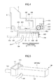
- FIG. 1 is a plan view of a mechanical section of an apparatus for ejecting liquids according to a first embodiment
- FIG. 2 is a schematic view of heads of the apparatus according to the first embodiment
- FIG. 3 is a block diagram of a control unit of the apparatus according to the first embodiment
- FIG. 4 is a lateral view of a carriage and an ejection detector according to the first embodiment in a state in which the ejection detector opposes the heads;
- FIG. 5 a partial perspective view of the ejection detector according to the first embodiment
- FIG. 6 is a partial perspective view of the ejection detector in which the ejection detector is partly cut out according to the first embodiment
- FIG. 7 is a block diagram of an ejection detection part according to the first embodiment
- FIG. 8 is a graph which indicates detection output of the ejection detection part according to the first embodiment
- FIG. 9 is a drawing illustrating an example of the first embodiment for describing an effect of the first embodiment
- FIG. 10 is a drawing of a comparative example for describing a problem of the comparative example
- FIG. 11 is a conceptual drawing of the ejection detector according to a second embodiment.
- FIG. 12 is a conceptual drawing of the ejection detector according to a third embodiment.
- FIG. 1 is a plan view of a mechanical section of the apparatus for ejecting liquids.
- the apparatus is a serial-type apparatus.
- a carriage 3 is supported by a main guide member 1 and a sub guide member (not shown) so as to be movable.
- the main guide member 1 and the sub guide member extend between left and right side plates (not shown).
- a main scanning motor 5 reciprocally moves the carriage 3 in a main scanning direction (a moving direction of the carriage 3 ) MSD via a timing belt 8 held by a driving pulley 6 and a driven pulley 7 .
- Liquid ejection heads 4 a and 4 b are mounted on the carriage 3 .
- the heads 4 eject, for example, liquids (ink) of respective colors, such as yellow (Y), cyan (C), magenta (M), and black (K).
- nozzle rows Na and Nb are arranged on each of the heads 4 .
- Each of the nozzle rows Na and Nb includes a plurality of nozzles 4 n , in a sub scanning direction SSD perpendicular to the main scanning direction MSD. The liquids are ejected downward from the nozzles.
- FIG. 2 is a schematic view of the heads 4 of the apparatus for ejecting the liquids according to the first embodiment.
- each of the heads 4 includes two nozzle rows Na and Nb.
- Each of nozzle rows Na and Nb includes the nozzles 4 n .
- the nozzle row Na of the head 4 a ejects liquid droplets of black (K), and the nozzle row Nb of the head 4 a ejects liquid droplets of cyan (C).
- the nozzle row Na of the head 4 b ejects liquid droplets of magenta (M), and the nozzle row Nb of the head 4 b ejects liquid droplets of yellow (Y).
- the apparatus includes a conveyance belt 12 , which is a conveyance unit, for conveying and holding a sheet 10 , which is a medium, at a position opposite to the heads 4 .
- the conveyance belt 12 is an endless belt and held by a conveyance roller 13 and a tension roller 14 .
- the conveyance roller 13 is rotated by a sub-scanning motor 16 via a timing belt 17 and a timing pulley 18 in order to circulate the conveyance belt 12 in the sub-scanning direction SSD.
- the conveyance belt 12 holds the sheet 10 with electrostatic attraction or air suction.
- a maintenance recovery mechanism 20 is disposed near a lateral side of the conveyance belt 12 .
- the maintenance recovery mechanism 20 performs maintenance and recovery of the heads 4 .
- an idle ejection receiving portion 21 for performing idle ejection is disposed at the lateral side of the conveyance belt 12 .
- the maintenance recovery mechanism 20 includes, for example, cap members 20 a which cap nozzle faces (faces on which the nozzles 4 n are formed) of the heads 4 , a wiper member 20 b which wipes the nozzle faces, and an idle ejection receiving portion to which liquids are ejected for keeping and recovering ejection capability (discharging performance).
- an ejection detector 100 according to the first embodiment which constitutes an ejection detection apparatus, is disposed in an area in which the ejection detector 100 can oppose (face) the heads 4 .
- the ejection detection apparatus according to the first embodiment detects whether the liquids are ejected from the nozzle(s) 4 n of the head(s) 4 .
- the carriage 3 includes a wiping unit 200 which cleans a face to which the liquids adhere of the ejection detector 100 .
- an encoder scale 23 having a predetermined pattern extends between the side plates along the main scanning direction MSD of the carriage 3 .
- a main scanning encoder sensor 24 is disposed on the carriage 3 .
- the encoder sensor 24 includes a transmissive photosensor which reads the pattern of the encoder scale 23 .
- the encoder scale 23 and the main scanning encoder sensor 24 constitute a linear encoder (main scanning encoder) which detects movement of the carriage 3 .
- a code wheel 25 is mounted on a shaft of the conveyance roller 13 .
- a sub scanning encoder sensor 26 includes a transmissive photosensor which detects a pattern formed in the code wheel 25 .
- the code wheel 25 and the sub scanning encoder sensor 26 constitute a rotary encoder (sub scanning encoder) which detects the movement amount and movement position of the conveyance belt 12 .
- the sheet 10 is fed from a sheet feed tray (not shown) by holding the sheet 10 on the conveyance belt 12 , and conveyed in the sub-scanning direction SSD according to the circulation of the conveyance belt 12 .
- the liquids are ejected onto the stopped sheet 10 in order to form one line of an image. Then, after the sheet 10 is fed by a certain distance, an operation for recording next line of the image is performed.
- the apparatus finishes the recording operation and discharges the sheet 10 to a sheet discharge tray (not shown).
- FIG. 3 is a block diagram of the control unit 500 of the apparatus.
- the control unit 500 includes a main control unit 500 A.
- the main control unit 500 A includes a central processing unit (CPU) 501 , a read-only memory (ROM) 502 , and a random access memory (RAM) 503 .
- the CPU 501 performs the overall control of the apparatus.
- the ROM 502 stores programs executed by the CPU 501 and other fixed data.
- the RAM 503 temporarily stores image data and other data.
- control unit 500 includes a host interface (I/F) 506 which transmits and receives data to and from a host 600 (information processing apparatus), such as a personal computer (PC).
- host interface (I/F) 506 which transmits and receives data to and from a host 600 (information processing apparatus), such as a personal computer (PC).
- the control unit 500 includes an image output control part 511 which controls driving of the heads 4 , and an encoder analyzing part 512 .
- the encoder analyzing part 512 inputs and analyzes detection signals from the main-scanning encoder sensor 24 and the sub-scanning encoder sensor 26 .
- control unit 500 includes a main-scanning motor driving part 513 which drives the main scanning motor 5 , a sub scanning motor driver 514 which drives the sub-scanning motor 16 , and an input/output (I/O) unit 516 connected to various sensors and actuators 517 .
- main-scanning motor driving part 513 which drives the main scanning motor 5
- sub scanning motor driver 514 which drives the sub-scanning motor 16
- I/O unit 516 connected to various sensors and actuators 517 .
- control unit 500 includes an ejection detection part 531 which measures (detects) electrical change when the liquid droplets land on an electrode board 101 of the ejection detector 100 in order to determine ejection or non-ejection. Further, the control unit 500 includes a wiping unit driving part 532 which drives a driving motor 203 of the wiping unit 200 which wipes the electrode board 101 of the ejection detector 100 .
- the image output control part 511 includes a data generation unit which generates print data, a driving waveform generation unit which generates driving waveforms for controlling driving of the heads 4 , and a data transmission unit which transmits the print data and head control signals for selecting desired driving signals from the driving waveforms.
- the image output control part 511 outputs the driving waveforms, the head control signals, the print data and the like to a head driver 510 , which is a head driving circuit for driving the heads 4 mounted on the carriage 3 , in order to eject the liquids from the nozzles 4 n of the heads 4 based on the print data.
- the encoder analyzing part 512 includes a direction detection part 520 which detects the movement direction of the carriage 3 from detection signals and a counter 521 which detects the movement amount of the carriage 3 .
- the control unit 500 controls driving of the main scan motor 5 via the main scanning motor driving part 513 in order to control the movement of the carriage 3 . Further, the control unit 500 controls driving of the sub scanning motor 16 via sub scanning motor driving part 514 in order to control feeding of the sheet 10 .
- the main control unit 500 A of the control unit 500 moves the heads 4 to a position opposite to the ejection detector 100 and causes desired nozzles of the heads 4 to eject in order to determine ejection status based on detection signals from the ejection detection part 531 .
- FIG. 4 is a lateral view of the carriage 3 and the ejection detector 100 in a state in which the ejection detector 100 opposes (face) the heads 4 .
- FIG. 5 is a partial perspective view of the ejection detector 100 .
- FIG. 6 is a partial perspective view of the ejection detector 100 in which the ejection detector 100 is partly cut out.
- the ejection detector 100 includes a holder 103 which has a box shape.
- a receiver 102 which receives the liquids ejected from the heads 4 is integrally formed on the holder 103 .
- a wall part of the upper face of the holder 103 is the receiver 102 , and the upper face of the holder 103 to which the liquids ejected from the heads 4 adhere is a receiving face 102 a.
- an electrode board 101 which is an electrode, is disposed on an opposite side (back face) of the receiving face (adhering face) 102 a to which the liquids adhere. In this way, the electrode board 101 is covered with the receiver 102 . In the first embodiment, the electrode board 101 is arranged in a state in which the electrode board 101 contacts the back face of the receiver 102 .
- the holder 103 which includes a part serving as the receiver 102 , is an insulated member which is made of an insulated material, such as plastic. It is preferable to apply water repellent treatment to the receiving face 102 a of the receiver 102 .
- the electrode board 101 is, for example, a conductive metal plate made of a material such as SUS304 and copper alloy plated with nickel (Ni) or palladium (Pd).
- the electrode board 101 is electrically connected to the ejection detection part 531 via a lead cable 109 .
- an opening portion 110 is formed on the holder 103 at a terminal end side in a wiping direction of a wiping member 201 .
- a portion (edge portion) of the holder 103 forming the opening portion 110 also forms a wiper cleaner 111 which is a cleaning member.
- the wiper cleaner 111 removes waste liquid adhering to the wiping member 201 and cleans the wiping member 201 .
- the holder 103 includes a waste liquid tube 112 which forms a channel connected to a waste liquid tank (not shown) from a lower side of the opening portion 110 . Further, it is preferable to provide a suction pump on the channel, which is connected to the waste liquid tank, for forcibly discharging the waste liquid accumulated on a bottom portion of the opening portion 110 into the waste liquid tank.
- the wiping unit 200 is disposed on the carriage 3 .
- the wiping unit 200 includes the wiping member 201 which moves for wiping the liquids adhering to the receiving face 102 a of the receiver 102 along a nozzle arrangement direction.
- the wiping member 201 is attached on a timing belt 223 wound around a driving pulley 221 and a driven pulley 222 .
- the driving pulley 221 is rotated by the driving motor 203 which is a driving source attached on the carriage 3 via a worm gear 224 and a gear 225 , the wiping member 201 is circulated (moved) together with the timing belt 223 in a direction indicated by an arrow A shown in FIG. 4 .
- the wiping unit 200 includes a wiper retraction cover 204 which covers the wiping member 201 at a retraction position.
- the wiping member 201 is accommodated in the wiper retraction cover 204 .
- Such a configuration can prevent a slight amount of waste liquids adhering to the wiping member 201 from scattering during operation of the carriage 3 .
- the ejection detection apparatus may be constructed with, for example, a combination of the ejection detector 100 and the wiping unit 200 , a combination of the ejection detector 100 and the ejection detection part 531 , a combination of the ejection detector 100 and the main control unit 500 A, or the like.
- FIG. 7 is a block diagram of the ejection detection part 531 .
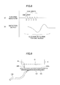
- FIG. 8 is a graph which indicates detection output of the ejection detection part 531 .
- the ejection detection part 531 includes a high-voltage power source 701 which supplies a high voltage VE (for example, 750 V) to the electrode board 101 .
- the main control unit 500 A controls on and off states of the high-voltage power source 701 .
- the ejection detection part 531 includes a band pass filter (BPF) 702 which inputs signals responding to electrical changes that occur when the ejected liquids adhere to the receiving face 102 a of the receiver 102 , an amplification (AMP) circuit 703 which amplifies the signals, and an analog-digital converter (ADC) 704 which converts the amplified signals from analog format to digital format.
- BPF band pass filter
- AMP amplification
- ADC analog-digital converter
- the main control unit 500 A causes the nozzle faces 41 of the heads 4 to oppose the electrode board 101 , and the high voltage VE is supplied to the electrode board 101 in order to generate a potential difference (electrical potential difference) between the nozzle faces 41 and the electrode board 101 .
- the nozzle faces 41 of the heads 4 are charged negatively, and the electrode board 101 is charged positively.
- the liquids for detection are ejected from each of the nozzles 4 n of the heads 4 .
- the liquid droplets are ejected from the nozzle face 41 of the head 4 which is charged negatively, the liquids are also charged negatively.
- the voltage of the high voltage VE supplied to the electrode board 101 slightly fluctuates (changes).
- the band-pass filter 702 extracts such voltage change (AC component), and the amplification circuit 703 amplifies the signal corresponding to the voltage change.
- the ADC 704 converts the amplified component from analog format to digital format and inputs the converted data as a measurement result (detection result) to the main control unit 500 A.
- detection output (AC component) is obtained as shown in FIG. 8( b ) if the nozzle ejects normally.
- the main control unit 500 A determines whether the measurement result (corresponding to the fluctuation) is greater than a preset threshold, and when the measurement result is greater than the preset threshold, the main control unit 500 A determines that a detected nozzle of the head 4 has ejected a liquid droplet(s). On the other hand, when the measurement result is not greater than the threshold value, the main control unit 500 A determines that the detected nozzle of the head 4 has not ejected the liquid droplet(s).
- the first embodiment can give, to two nozzles, waveforms for ejecting at the same time, and compare the detection outputs with two preset thresholds in order to determine whether both of the two nozzles eject, one of the two nozzles ejects, or neither of the two nozzles eject.
- the voltage VE supplied to the electrode board 101 is turned into off state.
- the ejection detector 100 can detect whether the liquids are ejected by detecting the electrical change generated when the liquids adhere to the receiving face 102 a of the receiver 102 while generating the potential difference generated between the heads 4 and the electrode board 101 .
- FIG. 9 is a drawing illustrating an example of the first embodiment for describing an effect of the first embodiment.
- FIG. 10 is a drawing of a comparative example for describing a problem of the comparative example.
- the comparative example does not include the receiver 102 of the first embodiment.
- the nozzle faces 41 of the heads 4 and the electrode board 101 are directly opposing to each other and the liquids are landed on the face of the electrode board 101 .
- a short circuit between the electrode board 101 and the heads may occur via a liquid column 300 due to fluctuation of a gap G between the heads 4 and the electrode board 101 and fluctuation of a length of the liquids ejected from the nozzles 4 n.
- the high potential difference (for example, 600 V to 800 V) is supplied between the heads 4 and the electrode board 101 .
- the liquids in the heads 4 are electrolyzed and bubbles are generated in a channel in the heads 4 when the short circuit occurs between the heads 4 and the electrode board 101 .
- ejection abnormality such as curving of ejecting and an ejection error may occur.
- the receiver 102 which is the insulated receiver, receives the liquids ejected from the heads 4 , and the electrode board 101 is disposed on the opposite side of the receiver 102 with respect to the heads 4 .
- the short circuit of the electrode board 101 and the heads 4 does not occur even when the liquid column 300 connects the heads 4 and the receiver 102 due to the fluctuation of the gap between the heads 4 and the electrode board 101 and the length of the liquids ejected from the nozzles 4 n.
- the ejection detecRFtion unit 100 can reduce the ejection abnormality due to the short circuit and perform the ejection detection with high reliability.
- the apparatus according to the first embodiment can eject the liquids which have a length connecting the heads 4 and the receiver 102 , like the liquid column 300 , when performing the ejection detection.
- the electrical change generated in the electrode board 101 is increased by ejecting the liquids which have the length connecting the heads 4 and the receiver 102 .
- capability of the ejection detection can be improved.
- the receiver 102 is formed as a part of the holder 103 which has the box shape, and the electrode board 101 is disposed in the holder 103 such that the holder 103 covers the electrode board 101 .
- the ejection detector according 100 to the first embodiment can maintain the insulation between the electrode board 101 and the housing of the apparatus, whose electrical potential is 0 V (GND), while some liquids drip downward in the gravity direction. Thus, the noise is not generated in the first embodiment.
- FIG. 11 is a conceptual drawing of the ejection detector 100 according to the second embodiment.
- the receiver 102 which is the insulated receiver, is disposed apart from the electrode board 101 by a gap Ga. It should be noted that other configurations of the second embodiment may be similar to the configurations of the first embodiment.
- the detection status can be detected because the electrical potential of the electrode board 101 changes according to the liquids charged in a reverse polarity approaching the electrode board 101 charged via the receiver 102 .
- FIG. 12 is a conceptual drawing of the ejection detector 100 according to the third embodiment.
- an insulated film 102 A is formed on the surface of the electrode board 101 .
- the insulated film 102 A serves as the receiver. It should be noted that other configurations of the third embodiment may be similar to the configurations of the first embodiment.
- the insulated film 102 A is formed on the entire face of the electrode board 101 in the third embodiment, the present invention is not limited to this.
- the insulated film 102 A may be formed on at least a face side of the electrode board 101 opposite to the heads 4 .
- effects similar to the effects of the first embodiment can be obtained, because the insulated film 102 A intervenes between the electrode board 101 and the heads 4 , and the short circuit of the electrode board 101 and the heads 4 due to the liquid column 300 does not occur.
- the apparatus for ejecting liquids indicates an apparatus which includes a liquid ejection head or a liquid ejection unit and drives the liquid ejection head or the liquid ejection unit in order to eject the liquids.
- An apparatus which is able to eject the liquids to a medium (object to which the liquids adhere) to which the liquids can adhere may be used as the apparatus for ejecting the liquids.
- the apparatus for ejecting the liquids may include the liquid ejection head or the liquid ejection unit, a control unit configured to control operation of the liquid ejection, a unit configured to feed, to convey, and to discharge the object to which the liquids adhere and another apparatus such as a preprocessing apparatus and a post processing apparatus.
- a recording apparatus a printing apparatus, an image forming apparatus, a liquid droplets ejection apparatus, a liquids ejection apparatus, a process liquids coating apparatus, a solid shaping apparatus, an apparatus which generates minute particles by a spray granulation method, a printer, a multifunction peripheral (MFP), a three-dimensional (3D) printer and the like may be used as “the apparatus for ejecting the liquids”.
- the apparatus for ejecting the liquids is not limited to an apparatus which generates (visualize) meaningful images such as characters and figures by ejecting the liquids.
- an apparatus which generates meaningless images such as patterns or three dimensional images may be used as the apparatus for ejecting the liquids.
- the above described “medium to which the liquids can adhere” indicates a medium to which the liquids can adhere even temporarily.
- the “medium to which the liquids can adhere” may be made of a material, to which the liquids can adhere even temporarily, such as paper, string, fiber, cloth, leather, metal, plastic, glass, timber, and ceramic.
- ink process liquid
- DNA samples resist, pattern material, a binding agent, shaping liquid and the like may be used for the “liquids”.
- a serial-type apparatus which moves the liquid ejection heads or a line-type apparatus which does not move the liquid ejection heads may be used as “the apparatus for ejecting the liquids” unless limited specifically.
- the liquid ejection unit includes the liquid ejection head(s), another functional part, and another mechanism integrally and indicates an aggregation of parts which correspond to the ejection of the liquids.
- the liquid ejection unit may include a configuration in which at least one of a head tank, a carriage, a supplying mechanism, a maintenance mechanism, and a main scanning movement mechanism is arbitrarily combined with the liquid ejection head.
- the main scanning movement mechanism is a mechanism for moving the liquid ejection head(s) in the main scanning direction.
- the main scanning movement mechanism may be constructed by combining a guide member which guides the liquid ejection head or the carriage, the driving source, and a movement mechanism of the carriage.
- the guide member single body may be included in the main scanning movement mechanism.
- the supplying mechanism is a mechanism for supplying the liquids stored outside of the liquid ejection head to the liquid ejection head.
- the supplying mechanism may include a mounting portion for mounting a liquid cartridge and a tube.
- the tube single body or the mounting portion single body may be included in the supplying mechanism.
- the maintenance mechanism is a mechanism for performing maintenance and recovery of capability of the liquid ejection head(s).
- the maintenance mechanism may have a configuration in which at least two of a cap, a wiping member, a suction unit connected to the cap such as a suction pump, and an idle receiving portion are combined.
- the mechanism in which the liquid ejection head and the other functional part/mechanism are integrated may have a fasten member, glue or heat caulking for fixing, a tube for connecting, or members engaging each other (including members in which one member slidably engages with the other member).
- the present invention is not limited to the configuration in which the liquid ejection head and the other functional part/mechanism are fixed, connected, or engaged, directly.
- the present invention may use a configuration in which the liquid ejection head and the other functional part/mechanism are fixed, connected, engaged via an intermediate member.
- the liquid ejection head and the head tank are fixed with the fasten member, the glue or the like in order to integrate the liquid ejection head and the head tank may be used for the liquid ejection unit.
- a configuration in which the liquid ejection head and the head tank are connected to each other by the tube or the like in order to integrate the liquid ejection head and the head tank may be used for the liquid ejection unit.
- the liquid ejection unit may include a unit including a filter between the head tank and the liquid ejection head.
- liquid ejection head and the carriage are fixed with the fasten member, the glue or the like in order to integrate the liquid ejection head and the carriage may be used for the liquid ejection unit.
- a configuration in which the liquid ejection head and the carriage are fixed via an attachment member for attaching in order to integrate the liquid ejection head and the carriage may be used for the liquid ejection unit.
- a configuration in which the liquid ejection head slidably engages (or, attaches) with a guide member forming a part of the main scanning movement mechanism in order to integrate the liquid ejection head and the main scanning movement mechanism may be used for the liquid ejection unit.
- a configuration in which the carriage, on which the liquid ejection head is attached, slidably engages (or, attaches) with the guide member forming the part of the main scanning movement mechanism in order to integrate the liquid ejection head and the main scanning movement mechanism may be used for the liquid ejection unit.
- a configuration in which the liquid ejection head and a cap which is a part of the maintenance mechanism are fixed with the fasten member or the like in order to integrate the liquid ejection head and the maintenance mechanism may be used for the liquid ejection unit.
- a configuration in which the carriage, on which the liquid ejection head is attached, and the cap, which is the part of the maintenance mechanism, are fixed with the fasten member or the like in order to integrate the liquid ejection head and the maintenance mechanism may be used for the liquid ejection unit.
- a configuration in which a tube for supplying the liquids from the outside to the inside of the liquid ejection head is connected to the liquid ejection head in order to integrate the liquid ejection head and the supplying mechanism may be used for the liquid ejection unit.
- a configuration in which a channel part to which the tube is connected is attached to the liquid ejection head in order to integrate the liquid ejection head and the supplying mechanism via the channel part may be used for the liquid ejection unit.
- a configuration in which the head tank to which the tube is connected is attached to the liquid ejection head in order to integrate the liquid ejection head and head tank may be used for the liquid ejection unit.
- the liquid ejection head the carriage, the main scanning mechanism, the maintenance mechanism and the supplying mechanism are integrated may be used as “the liquid ejection unit”.
- a pressure generation unit used for “the liquid ejection head” is not limited.
- a piezoelectric actuator laminated piezoelectric element may be used
- a thermal actuator using an electricity-heat conversion element such as a heat resistance element, or an electrostatic actuator including a vibration plate and a counter electrode may be used.
Landscapes
- Ink Jet (AREA)
Abstract
Description
Claims (9)
Applications Claiming Priority (2)
| Application Number | Priority Date | Filing Date | Title |
|---|---|---|---|
| JP2015-039894 | 2015-03-02 | ||
| JP2015039894A JP2016159503A (en) | 2015-03-02 | 2015-03-02 | Device for discharging liquid, discharge detection device, and discharge detection unit |
Publications (2)
| Publication Number | Publication Date |
|---|---|
| US20160257113A1 US20160257113A1 (en) | 2016-09-08 |
| US9533496B2 true US9533496B2 (en) | 2017-01-03 |
Family
ID=56843902
Family Applications (1)
| Application Number | Title | Priority Date | Filing Date |
|---|---|---|---|
| US15/046,573 Expired - Fee Related US9533496B2 (en) | 2015-03-02 | 2016-02-18 | Apparatus for ejecting liquids, ejection detection apparatus, and ejection detector |
Country Status (2)
| Country | Link |
|---|---|
| US (1) | US9533496B2 (en) |
| JP (1) | JP2016159503A (en) |
Cited By (2)
| Publication number | Priority date | Publication date | Assignee | Title |
|---|---|---|---|---|
| US11400705B2 (en) | 2020-03-26 | 2022-08-02 | Brother Kogyo Kabushiki Kaisha | Liquid ejection apparatus |
| US11618251B2 (en) | 2020-03-31 | 2023-04-04 | Brother Kogyo Kabushiki Kaisha | Liquid ejection apparatus |
Families Citing this family (8)
| Publication number | Priority date | Publication date | Assignee | Title |
|---|---|---|---|---|
| US10907055B2 (en) | 2016-02-02 | 2021-02-02 | Sensor Electronic Technology, Inc. | Curing ultraviolet sensitive polymer materials |
| US10226929B2 (en) | 2016-11-10 | 2019-03-12 | Ricoh Company, Ltd. | Head cleaner, maintenance device, and liquid discharge apparatus |
| JP2019074609A (en) * | 2017-10-13 | 2019-05-16 | キヤノン株式会社 | Image forming apparatus, information processing method, and program |
| US11161340B2 (en) | 2019-07-23 | 2021-11-02 | Ricoh Company, Ltd. | Liquid discharge apparatus |
| US11173717B2 (en) | 2019-07-24 | 2021-11-16 | Ricoh Company, Ltd. | Liquid discharge apparatus |
| US11235570B2 (en) | 2019-07-31 | 2022-02-01 | Ricoh Company, Ltd. | Liquid discharge apparatus |
| CN113650417B (en) * | 2020-05-12 | 2025-05-23 | 精工爱普生株式会社 | Liquid ejection device and dispensing system for liquid ejection head |
| JP7571537B2 (en) * | 2020-12-25 | 2024-10-23 | ブラザー工業株式会社 | Liquid ejection device |
Citations (7)
| Publication number | Priority date | Publication date | Assignee | Title |
|---|---|---|---|---|
| US7645007B2 (en) * | 2005-09-30 | 2010-01-12 | Seiko Epson Corporation | Ink jet recording apparatus, nozzle inspection method and program thereof |
| US20100302295A1 (en) * | 2009-05-29 | 2010-12-02 | Seiko Epson Corporation | Liquid ejecting head inspection apparatus, liquid ejecting apparatus, and inspection method of liquid ejecting head inspection apparatus |
| JP2014097642A (en) | 2012-11-15 | 2014-05-29 | Ricoh Co Ltd | Image forming apparatus |
| US8919921B2 (en) | 2012-11-15 | 2014-12-30 | Ricoh Company, Ltd. | Image forming apparatus |
| US8967759B2 (en) | 2013-03-07 | 2015-03-03 | Ricoh Company, Ltd. | Image forming apparatus |
| US20150062223A1 (en) | 2013-09-04 | 2015-03-05 | Ricoh Company, Ltd. | Image forming apparatus and droplet discharge detector |
| US9028039B2 (en) | 2013-10-07 | 2015-05-12 | Ricoh Company, Ltd. | Image forming apparatus |
Family Cites Families (4)
| Publication number | Priority date | Publication date | Assignee | Title |
|---|---|---|---|---|
| US6951379B2 (en) * | 2003-04-09 | 2005-10-04 | Hewlett-Packard Development Company, L.P. | Print head charge shield |
| JP4946012B2 (en) * | 2005-11-18 | 2012-06-06 | セイコーエプソン株式会社 | Image forming apparatus, print head inspection method and program thereof |
| JP2008049511A (en) * | 2006-08-23 | 2008-03-06 | Seiko Epson Corp | Discharge inspection apparatus, discharge inspection method, and inspection program |
| JP2011084043A (en) * | 2009-10-19 | 2011-04-28 | Seiko Epson Corp | Ejection examination apparatus and printing apparatus |
-
2015
- 2015-03-02 JP JP2015039894A patent/JP2016159503A/en active Pending
-
2016
- 2016-02-18 US US15/046,573 patent/US9533496B2/en not_active Expired - Fee Related
Patent Citations (7)
| Publication number | Priority date | Publication date | Assignee | Title |
|---|---|---|---|---|
| US7645007B2 (en) * | 2005-09-30 | 2010-01-12 | Seiko Epson Corporation | Ink jet recording apparatus, nozzle inspection method and program thereof |
| US20100302295A1 (en) * | 2009-05-29 | 2010-12-02 | Seiko Epson Corporation | Liquid ejecting head inspection apparatus, liquid ejecting apparatus, and inspection method of liquid ejecting head inspection apparatus |
| JP2014097642A (en) | 2012-11-15 | 2014-05-29 | Ricoh Co Ltd | Image forming apparatus |
| US8919921B2 (en) | 2012-11-15 | 2014-12-30 | Ricoh Company, Ltd. | Image forming apparatus |
| US8967759B2 (en) | 2013-03-07 | 2015-03-03 | Ricoh Company, Ltd. | Image forming apparatus |
| US20150062223A1 (en) | 2013-09-04 | 2015-03-05 | Ricoh Company, Ltd. | Image forming apparatus and droplet discharge detector |
| US9028039B2 (en) | 2013-10-07 | 2015-05-12 | Ricoh Company, Ltd. | Image forming apparatus |
Cited By (2)
| Publication number | Priority date | Publication date | Assignee | Title |
|---|---|---|---|---|
| US11400705B2 (en) | 2020-03-26 | 2022-08-02 | Brother Kogyo Kabushiki Kaisha | Liquid ejection apparatus |
| US11618251B2 (en) | 2020-03-31 | 2023-04-04 | Brother Kogyo Kabushiki Kaisha | Liquid ejection apparatus |
Also Published As
| Publication number | Publication date |
|---|---|
| JP2016159503A (en) | 2016-09-05 |
| US20160257113A1 (en) | 2016-09-08 |
Similar Documents
| Publication | Publication Date | Title |
|---|---|---|
| US9533496B2 (en) | Apparatus for ejecting liquids, ejection detection apparatus, and ejection detector | |
| US6935717B2 (en) | Ink drop detector configurations | |
| US9028039B2 (en) | Image forming apparatus | |
| US9694584B2 (en) | Liquid ejector and liquid ejecting detector | |
| US8967759B2 (en) | Image forming apparatus | |
| JP2009072973A (en) | Liquid ejection apparatus, control method thereof, and program thereof | |
| US20160152033A1 (en) | Liquid Ejecting Apparatus, Ultrasonic Cleaning Device, and Ultrasonic Cleaning Method | |
| CN101087688B (en) | Printing apparatus and printing method | |
| JP2017071067A (en) | Device and program for discharging liquid | |
| US8919921B2 (en) | Image forming apparatus | |
| JP2009269313A (en) | Ink-jet recording device and pre-ejection method | |
| JP5088708B2 (en) | Liquid discharge inspection apparatus and liquid discharge inspection method | |
| US20100165035A1 (en) | Discharge inspection apparatus, fluid discharging apparatus, and method for working shield cable | |
| JP2010201854A (en) | Device, apparatus and method for inspecting ejection | |
| JP2013111794A (en) | Device, and method for inspecting liquid discharge, printing apparatus, and program | |
| JP2018075784A (en) | Liquid discharge detector and device for discharging liquid | |
| JP2010201853A (en) | Ejection inspecting device, fluid ejecting apparatus and ejection inspecting method | |
| JP2013111769A (en) | Device, and method for inspecting liquid discharge, printing apparatus, and program | |
| JP2012179796A (en) | Ejection detection device, liquid ejection device, and cleaning method | |
| JP2009160833A (en) | Ink jet printer, nozzle cleaning method and control program for ink jet printer | |
| JP4752418B2 (en) | Inkjet printer | |
| JP2007098571A (en) | Print head inspection apparatus, printing apparatus, print head inspection method and program thereof | |
| JP2017052131A (en) | Device discharging liquid, program and discharge detecting method | |
| JP2017043066A (en) | Device for discharging liquid | |
| JP2006346907A (en) | Droplet ejection apparatus, droplet ejection system, droplet ejection detection method, and droplet ejection detection program |
Legal Events
| Date | Code | Title | Description |
|---|---|---|---|
| AS | Assignment |
Owner name: RICOH COMPANY, LTD., JAPAN Free format text: ASSIGNMENT OF ASSIGNORS INTEREST;ASSIGNORS:TAKEUCHI, SHOTARO;SAITO, SHOHEI;KIKUCHI, TAKAHIRO;REEL/FRAME:037772/0636 Effective date: 20160217 |
|
| FEPP | Fee payment procedure |
Free format text: PAYOR NUMBER ASSIGNED (ORIGINAL EVENT CODE: ASPN); ENTITY STATUS OF PATENT OWNER: LARGE ENTITY |
|
| STCF | Information on status: patent grant |
Free format text: PATENTED CASE |
|
| AS | Assignment |
Owner name: RICOH COMPANY, LTD., JAPAN Free format text: ASSIGNMENT OF ASSIGNORS INTEREST;ASSIGNORS:TAKEUCHI, SHOTARO;SAITO, SHOHEI;KIKUCHI, TAKAHIRO;REEL/FRAME:042491/0766 Effective date: 20160217 |
|
| MAFP | Maintenance fee payment |
Free format text: PAYMENT OF MAINTENANCE FEE, 4TH YEAR, LARGE ENTITY (ORIGINAL EVENT CODE: M1551); ENTITY STATUS OF PATENT OWNER: LARGE ENTITY Year of fee payment: 4 |
|
| FEPP | Fee payment procedure |
Free format text: MAINTENANCE FEE REMINDER MAILED (ORIGINAL EVENT CODE: REM.); ENTITY STATUS OF PATENT OWNER: LARGE ENTITY |
|
| LAPS | Lapse for failure to pay maintenance fees |
Free format text: PATENT EXPIRED FOR FAILURE TO PAY MAINTENANCE FEES (ORIGINAL EVENT CODE: EXP.); ENTITY STATUS OF PATENT OWNER: LARGE ENTITY |
|
| STCH | Information on status: patent discontinuation |
Free format text: PATENT EXPIRED DUE TO NONPAYMENT OF MAINTENANCE FEES UNDER 37 CFR 1.362 |
|
| FP | Lapsed due to failure to pay maintenance fee |
Effective date: 20250103 |