US9528379B2 - Turbine bucket having serpentine core - Google Patents
Turbine bucket having serpentine core Download PDFInfo
- Publication number
- US9528379B2 US9528379B2 US14/061,363 US201314061363A US9528379B2 US 9528379 B2 US9528379 B2 US 9528379B2 US 201314061363 A US201314061363 A US 201314061363A US 9528379 B2 US9528379 B2 US 9528379B2
- Authority
- US
- United States
- Prior art keywords
- leading edge
- bucket
- casing
- airfoil
- core
- Prior art date
- Legal status (The legal status is an assumption and is not a legal conclusion. Google has not performed a legal analysis and makes no representation as to the accuracy of the status listed.)
- Active, expires
Links
Images


Classifications
-
- F—MECHANICAL ENGINEERING; LIGHTING; HEATING; WEAPONS; BLASTING
- F01—MACHINES OR ENGINES IN GENERAL; ENGINE PLANTS IN GENERAL; STEAM ENGINES
- F01D—NON-POSITIVE DISPLACEMENT MACHINES OR ENGINES, e.g. STEAM TURBINES
- F01D5/00—Blades; Blade-carrying members; Heating, heat-insulating, cooling or antivibration means on the blades or the members
- F01D5/12—Blades
- F01D5/14—Form or construction
- F01D5/18—Hollow blades, i.e. blades with cooling or heating channels or cavities; Heating, heat-insulating or cooling means on blades
- F01D5/187—Convection cooling
-
- B—PERFORMING OPERATIONS; TRANSPORTING
- B22—CASTING; POWDER METALLURGY
- B22C—FOUNDRY MOULDING
- B22C9/00—Moulds or cores; Moulding processes
- B22C9/10—Cores; Manufacture or installation of cores
-
- B—PERFORMING OPERATIONS; TRANSPORTING
- B22—CASTING; POWDER METALLURGY
- B22C—FOUNDRY MOULDING
- B22C9/00—Moulds or cores; Moulding processes
- B22C9/10—Cores; Manufacture or installation of cores
- B22C9/103—Multipart cores
-
- B—PERFORMING OPERATIONS; TRANSPORTING
- B22—CASTING; POWDER METALLURGY
- B22C—FOUNDRY MOULDING
- B22C9/00—Moulds or cores; Moulding processes
- B22C9/22—Moulds for peculiarly-shaped castings
- B22C9/24—Moulds for peculiarly-shaped castings for hollow articles
-
- F—MECHANICAL ENGINEERING; LIGHTING; HEATING; WEAPONS; BLASTING
- F01—MACHINES OR ENGINES IN GENERAL; ENGINE PLANTS IN GENERAL; STEAM ENGINES
- F01D—NON-POSITIVE DISPLACEMENT MACHINES OR ENGINES, e.g. STEAM TURBINES
- F01D5/00—Blades; Blade-carrying members; Heating, heat-insulating, cooling or antivibration means on the blades or the members
- F01D5/12—Blades
- F01D5/14—Form or construction
- F01D5/147—Construction, i.e. structural features, e.g. of weight-saving hollow blades
-
- F—MECHANICAL ENGINEERING; LIGHTING; HEATING; WEAPONS; BLASTING
- F05—INDEXING SCHEMES RELATING TO ENGINES OR PUMPS IN VARIOUS SUBCLASSES OF CLASSES F01-F04
- F05D—INDEXING SCHEME FOR ASPECTS RELATING TO NON-POSITIVE-DISPLACEMENT MACHINES OR ENGINES, GAS-TURBINES OR JET-PROPULSION PLANTS
- F05D2230/00—Manufacture
- F05D2230/20—Manufacture essentially without removing material
- F05D2230/21—Manufacture essentially without removing material by casting
- F05D2230/211—Manufacture essentially without removing material by casting by precision casting, e.g. microfusing or investment casting
-
- F—MECHANICAL ENGINEERING; LIGHTING; HEATING; WEAPONS; BLASTING
- F05—INDEXING SCHEMES RELATING TO ENGINES OR PUMPS IN VARIOUS SUBCLASSES OF CLASSES F01-F04
- F05D—INDEXING SCHEME FOR ASPECTS RELATING TO NON-POSITIVE-DISPLACEMENT MACHINES OR ENGINES, GAS-TURBINES OR JET-PROPULSION PLANTS
- F05D2250/00—Geometry
- F05D2250/10—Two-dimensional
- F05D2250/18—Two-dimensional patterned
- F05D2250/185—Two-dimensional patterned serpentine-like
-
- F—MECHANICAL ENGINEERING; LIGHTING; HEATING; WEAPONS; BLASTING
- F05—INDEXING SCHEMES RELATING TO ENGINES OR PUMPS IN VARIOUS SUBCLASSES OF CLASSES F01-F04
- F05D—INDEXING SCHEME FOR ASPECTS RELATING TO NON-POSITIVE-DISPLACEMENT MACHINES OR ENGINES, GAS-TURBINES OR JET-PROPULSION PLANTS
- F05D2250/00—Geometry
- F05D2250/70—Shape
- F05D2250/74—Shape given by a set or table of xyz-coordinates
-
- Y—GENERAL TAGGING OF NEW TECHNOLOGICAL DEVELOPMENTS; GENERAL TAGGING OF CROSS-SECTIONAL TECHNOLOGIES SPANNING OVER SEVERAL SECTIONS OF THE IPC; TECHNICAL SUBJECTS COVERED BY FORMER USPC CROSS-REFERENCE ART COLLECTIONS [XRACs] AND DIGESTS
- Y02—TECHNOLOGIES OR APPLICATIONS FOR MITIGATION OR ADAPTATION AGAINST CLIMATE CHANGE
- Y02T—CLIMATE CHANGE MITIGATION TECHNOLOGIES RELATED TO TRANSPORTATION
- Y02T50/00—Aeronautics or air transport
- Y02T50/60—Efficient propulsion technologies, e.g. for aircraft
-
- Y02T50/673—
-
- Y02T50/676—
Definitions
- the subject matter disclosed herein relates to turbomachines. More particularly, the subject matter disclosed herein relates to components within turbomachines such as gas and/or steam turbines.
- Gas turbine systems are one example of turbomachines widely utilized in fields such as power generation.
- a conventional gas turbine system includes a compressor section, a combustor section, and a turbine section.
- various components in the system are subjected to high temperature flows, which can cause the components to fail. Since higher temperature flows generally result in increased performance, efficiency, and power output of the gas turbine system, it may be desirable to cool the components that are subjected to high temperature flows to allow the gas turbine system to operate at increased temperatures.
- Various embodiments of the invention include turbine buckets and systems employing such buckets.
- Various particular embodiments include a turbine bucket having: a base; and an airfoil connected with the base at a first end of the airfoil, the airfoil including: a casing having: a suction side; a pressure side opposing the suction side; a leading edge spanning between the pressure side and the suction side; and a trailing edge opposing the leading edge and spanning between the pressure side and the suction side, the casing including an aperture on the leading edge; and a core within the casing, the core having a serpentine shape for supporting the casing and a leading edge passage fluidly connected with the aperture on the leading edge of the casing.
- a first aspect of the invention includes a turbine bucket having: a base; and an airfoil connected with the base at a first end of the airfoil, the airfoil including: a casing having: a suction side; a pressure side opposing the suction side; a leading edge spanning between the pressure side and the suction side; and a trailing edge opposing the leading edge and spanning between the pressure side and the suction side, the casing including an aperture on the leading edge; and a core within the casing, the core having a serpentine shape for supporting the casing and a leading edge passage fluidly connected with the aperture on the leading edge of the casing.
- a second aspect of the invention includes a turbine rotor section including: a set of buckets, the set of buckets including at least one bucket having: a base; and an airfoil connected with the base at a first end of the airfoil, the airfoil including: a casing having: a suction side; a pressure side opposing the suction side; a leading edge spanning between the pressure side and the suction side; and a trailing edge opposing the leading edge and spanning between the pressure side and the suction side, the casing including an aperture on the leading edge; and a core within the casing, the core having a serpentine shape for supporting the casing and a leading edge passage fluidly connected with the aperture on the leading edge of the casing.
- a third aspect of the invention includes a turbine having: a diaphragm section; and a rotor section at least partially contained within the diaphragm section, the rotor section having a set of buckets including at least one bucket having: a base; and an airfoil connected with the base at a first end of the airfoil, the airfoil including: a casing having: a suction side; a pressure side opposing the suction side; a leading edge spanning between the pressure side and the suction side; and a trailing edge opposing the leading edge and spanning between the pressure side and the suction side, the casing including an aperture on the leading edge; and a core within the casing, the core having a serpentine shape for supporting the casing and a leading edge passage fluidly connected with the aperture on the leading edge of the casing, wherein the at least one bucket has a nominal internal core profile substantially in accordance with Cartesian coordinate values of X, Y and Z set forth in Table I, wherein the Z values are
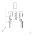
- FIG. 1 shows a three-dimensional partial cut-away perspective view of a portion of a turbine according to an embodiment of the invention.
- FIG. 2 shows a schematic three-dimensional depiction of a turbine bucket including an airfoil and a base according to various embodiments of the invention.
- FIG. 3 shows a perspective view of a core of the turbine bucket of FIG. 2 according to various embodiments of the invention.
- FIG. 4 shows a close-up perspective view of a base portion of the core of FIG. 3 .
- FIG. 5 shows a close-up perspective view of a metered inlet portion of the core of FIG. 3 .
- FIG. 6 shows a close-up perspective view of a non-asynchronous turn portion of the core of FIG. 3 .
- FIG. 7 shows a schematic block diagram illustrating portions of a multi-shaft combined cycle power plant system according to embodiments of the invention.
- FIG. 8 shows a schematic block diagram illustrating portions of a single-shaft combined cycle power plant system according to embodiments of the invention.
- FIGS. 1-9 are not necessarily to scale.
- the drawings are intended to depict only typical aspects of the invention, and therefore should not be considered as limiting the scope of the invention. It is understood that elements similarly numbered between the FIGURES may be substantially similar as described with reference to one another. Further, in embodiments shown and described with reference to FIGS. 1-9 , like numbering may represent like elements. Redundant explanation of these elements has been omitted for clarity. Finally, it is understood that the components of FIGS. 1-9 and their accompanying descriptions may be applied to any embodiment described herein.
- various aspects of the invention are directed toward turbine buckets.
- Particular aspects of the invention include turbine buckets having a serpentine core structure.
- aspects of the invention include a turbine bucket (e.g., a dynamic bucket for driving a turbine shaft) having a serpentine core reinforcement structure within its casing.
- the bucket can also include a leading edge passage fluidly connected with an aperture on the leading edge of the bucket.
- the serpentine core reinforcement structure can reinforce the bucket casing and provide enhanced stability when compared with conventional reinforcement structures. Additionally, the leading edge passage can reduce flow-related inefficiencies in a turbine employing the bucket. Further, as described herein, the serpentine core reinforcement structure can provide for enhanced heat transfer within and/or across one or more buckets employing such reinforcement structures.
- the terms “axial” and/or “axially” refer to the relative position/direction of objects along axis A, which is substantially parallel to the axis of rotation of the turbomachine (in particular, the rotor section).
- the terms “radial” and/or “radially” refer to the relative position/direction of objects along axis (r), which is substantially perpendicular with axis A and intersects axis A at only one location.
- the terms “circumferential” and/or “circumferentially” refer to the relative position/direction of objects along a circumference which surrounds axis A but does not intersect the axis A at any location.
- leading edge/pressure side refer to components and/or surfaces which are oriented upstream relative to the fluid flow of the system
- trailing edge/suction side refer to components and/or surfaces which are oriented downstream relative to the fluid flow of the system.
- Cartesian coordinate system used to define the shape of the serpentine core structure is defined further herein, and may operate independently from the axial, radial, etc., directional indicators.
- FIG. 1 shows a perspective partial cut-away illustration of a turbine 10 (e.g., a gas or steam turbine) according to various embodiments of the invention.
- Turbine 10 includes a rotor 12 that includes a rotating shaft 14 and a plurality of axially spaced rotor wheels 18 .
- a plurality of rotating buckets 20 (dynamic buckets) are mechanically coupled to each rotor wheel 18 . More specifically, buckets 20 are arranged in rows that extend circumferentially around each rotor wheel 18 .
- a diaphragm 21 is shown including a plurality of stationary blades (or, vanes) 22 that circumferentially around shaft 14 , and the blades 22 are axially positioned between adjacent rows of buckets 20 .
- Stationary blades 22 cooperate with buckets 20 to form a stage of the turbine 10 , and to define a portion of a flow path through turbine 10 .
- the diaphragm 21 at least partially surrounds the rotor 12 (shown in this cut-away view).
- the turbine 10 shown is a dual-flow turbine 10 that includes an axially centered inlet mouth which feeds two sets of turbine stages.
- axial turbines e.g., axial inlet gas turbines that inlet a combustion gas from a first axial end and outlet that combustion gas to a second axial end after the gas has performed mechanical work on the turbine.
- gas 24 enters an inlet 26 of turbine 10 and is channeled through stationary blades 22 . Blades 22 direct gas 24 against buckets 20 . Gas 24 passes through the remaining stages imparting a force on buckets 20 causing shaft 14 to rotate. At least one end of turbine 10 may extend axially away from rotating shaft 12 and may be attached to a load or machinery (not shown) such as, but not limited to, a generator, and/or another turbine.
- turbine 10 may include five stages.
- the five stages are referred to as L 0 , L 1 , L 2 , L 3 and L 4 .
- Stage L 4 is the first stage and is the smallest (in a radial direction) of the five stages.
- Stage L 3 is the second stage and is the next stage in an axial direction.
- Stage L 2 is the third stage and is shown in the middle of the five stages.
- Stage L 1 is the fourth and next-to-last stage.
- Stage L 0 is the last stage and is the largest (in a radial direction). It is to be understood that five stages are shown as one example only, and each turbine may have more or less than five stages. Also, as will be described herein, the teachings of the invention do not require a multiple stage turbine.
- turbine 10 may comprise an aircraft engine used to produce thrust.
- FIG. 2 a schematic three-dimensional depiction of a turbine bucket (or simply, bucket) 200 is shown according to various embodiments.
- the bucket 200 is a rotatable (dynamic) bucket which is part of a set of buckets circumferentially dispersed about a rotor shaft in a stage of a turbine (e.g., turbine 10 ). It is understood that in various embodiments, the bucket 200 can be implemented in a turbine (e.g., turbine 10 , FIG. 1 ), just as the bucket(s) 20 shown and described with respect to FIG. 1 .
- bucket 200 will rotate about the axis A as a working fluid (e.g., gas or steam) is directed across the bucket's airfoil, initiating rotation of a rotor shaft (e.g., shaft 14 ).
- a working fluid e.g., gas or steam
- rotor shaft e.g., shaft 14
- bucket 200 is configured to couple (mechanically couple via fasteners, welds, slot/grooves, etc.) with a plurality of similar or distinct buckets (e.g., buckets 200 or other buckets) to form a set of buckets in a stage of the turbine.
- the turbine bucket 200 can include an airfoil 202 having a suction side 204 (obstructed in this view), and a pressure side 206 opposing the suction side 204 .
- the bucket 200 can also include a leading edge 208 spanning between the pressure side 206 and the suction side 204 , and a trailing edge 210 opposing the leading edge 208 and spanning between the pressure side 206 and the suction side 204 .
- the casing 203 of the airfoil 202 is visible, as its core structure ( 300 , FIG. 3 ) is obstructed by the casing 203 .
- the core structure ( 300 , FIG. 3 ) will be described in greater detail herein.
- the bucket 200 can be a first stage (L 4 ) bucket, exposed to higher temperature and pressure working fluid (e.g., gas or steam) than buckets located in later stages (e.g., L 3 -L 0 ).
- higher temperature and pressure working fluid e.g., gas or steam
- later stages e.g., L 3 -L 0
- various aspects of the turbine bucket 200 allow for improved product life and performance in a turbine utilizing such a bucket.
- the bucket 200 can also include a base 212 connected with the airfoil 202 .
- the base 212 can be connected with the airfoil 202 along the suction side 204 , pressure side 206 , trailing edge 210 and the leading edge 208 .
- the bucket 200 includes a fillet 214 proximate a first end 215 of the airfoil 202 , the fillet 214 connecting the airfoil 202 and the base 212 .
- the fillet 214 can be cast (an as-cast feature) or include a weld or braze fillet, which may be formed via conventional MIG welding, TIG welding, brazing, etc.
- the base 212 is designed to fit into a mating slot in the turbine rotor shaft (e.g., shaft 14 ) and mate with adjacent base components of other buckets 200 .
- the base 212 is designed to be located radially inboard of the airfoil 202 .
- the base 212 can connect to a wheel of a rotor (e.g., connected with rotor shaft 14 ) via dovetail or firtree connection, via welding, or any other mechanical or physical connection.
- the airfoil 202 can include an aperture 218 along its leading edge 208 for permitting exhaust of cooling fluid from the core of the airfoil 202 to the exterior of the airfoil 202 .
- the aperture 218 can be fluidly connected with a passage in the core of the airfoil 202 , and together, the aperture 218 and the passage can permit exhaust of the working fluid from the core of the airfoil 202 to the exterior of the airfoil 202 .
- the coolant flow can enter the core (core structure 300 , FIG. 3 ) via the base section 212 , and can exit the core via one or more apertures 218 .
- one or more aperture(s) 218 can be located along the leading edge 208 , trailing edge 210 , or other surfaces of the airfoil 202 .
- FIG. 3 shows a schematic three-dimensional depiction of a core structure 300 within the casing 203 of the airfoil 202 .
- the core structure (or simply, core) 300 can have a serpentine shape 302 as further described herein.
- the core 300 can support the casing 203 of the airfoil 202 , and can extend radially from the base 212 ( FIG. 2 ) along the length of the airfoil 202 .
- the serpentine shape 302 can mechanically support the casing 203 ( FIG. 2 ), e.g., during utilization of the bucket 200 during operation of a turbine (e.g., a gas or steam turbine, as described herein). Also shown in FIG.
- the core 300 can include a leading edge passage 304 fluidly connected with the aperture 218 on the leading edge 208 of the airfoil casing 203 .
- the leading edge passage 304 can be fluidly connected with the aperture 218 on the leading edge 208 such that a coolant fluid, e.g., a cooling liquid, exhaust through the aperture 218 to an exterior of the airfoil 202 .
- a body shown can be an outline of cavities formed within airfoil 202 such that what appear to be outer surfaces of core 300 or portions thereof can actually be walls of the cavities the body represents or boundaries between the cavities and the solid material of bucket 200 and/or airfoil 202 .
- core 300 or a portion thereof as a form to be included in casting bucket 200 and/or airfoil 202 and later removed to leave the cavity(ies) that form core 300 .
- casting is only one of many ways in which bucket 200 , airfoil 202 , and/or core 300 can be made and/or formed.
- An alternative conceptualization of core 300 can include its formation with thin sheets of metal defining its inner and outer boundaries.
- the serpentine shaped core 302 includes a set of contiguous reinforcement members 310 extending substantially radially within the casing ( 203 ).
- the set of contiguous reinforcement members 310 can be formed of one or more substantially unitary pieces of material, e.g., a metal such as steel, aluminum and/or alloys of those metals.
- the set of contiguous reinforcement members 310 are formed as a substantially unitary structure, and can be integrally formed, e.g., via integral casting and/or forging.
- the contiguous reinforcement members 310 can be formed from separate reinforcement members that are bonded together to substantially eliminate seams or discontinuities between these separate members.
- a form can be made from a sacrificial material that can be placed in a mold for bucket 200 and/or airfoil 202 during casting of bucket 200 and/or airfoil 202 .
- a sacrificial material can be selected to withstand the conditions associated with casting, but can later be removed to leave the cavities that form core 300 in the otherwise substantially solid bucket 200 and/or airfoil 202 .
- the serpentine shaped core 302 can also include a set of support member chutes (or slots) 314 proximate one end 312 (a radially inner end) of the set of contiguous reinforcement member 310 .
- the set of support member chutes 314 can be sized to hold a support member ( FIG. 4 ).
- FIG. 4 shows a close-up view of the radially inner end 312 of several reinforcement members coupled with support member chutes 314 .
- a support member 316 can be housed within each support member chute 314 (radially inboard of the contiguous reinforcement members 310 ).
- each support member 316 can include a brazed or welded support ball or similar geometry, e.g., a substantially rounded braze or weld element formed of a metal such as silver, gold, palladium, copper, zinc, cobalt, nickel and/or alloys of one or more of these metals.
- at least one support member 316 can include a metering feature (e.g., metering features 338 , shown and described with reference to FIG. 5 ).
- the set of contiguous reinforcement members 310 can include a plurality of reinforcement fingers 320 , a set of radially inner turns 322 between adjacent reinforcement fingers 320 , and a set of radially outer turns 324 between adjacent reinforcement fingers 320 . It is understood that due to the serpentine nature of the reinforcement members 310 , in some cases, no radially inner turn 322 will join the same reinforcement fingers 320 as a radially outer turn 324 . That is, each reinforcement finger 320 will be coupled with a single radially inner turn 322 and a single radially outer turn 324 .
- At least one of the radially outer turns 324 in the set of radially outer turns 324 can include a non-asymmetric arc feature 326 such that the adjacent reinforcement fingers 320 are separated by a first distance (d 1 ) at a radially outermost portion 328 of the turn (outer turn 324 ) and are separated by a second distance, less than the first distance, at a radially inner portion 330 of the turn (the same outer turn 324 ).
- This non-asymmetric arc feature 326 can provide additional mechanical strength when compared to conventional bucket core support structures.
- at least one radially inner turn 322 can include a non-asymmetric arc feature 326 as described herein with reference to the radially outer turn(s) 324 .
- FIG. 5 shows a close-up perspective view of a section of the core structure 300 including the leading edge passage 304 .
- the aperture 218 on the leading edge 208 and the leading edge passage 304 are located closer to the base 212 than a radial tip 334 of the airfoil 202 .
- the base 212 is radially inboard of the airfoil 202
- the leading edge passage 304 and the aperture 218 are radially inboard of a radial mid-line (MLr) of the airfoil 202 .
- MLr radial mid-line
- the core 300 can also include an at least partially radially extending passage 336 fluidly connected with the aperture 218 on the leading edge 208 and the leading edge passage 304 . That is, the cooling fluid entering the core 300 via the radially inner end 312 (proximate the base 212 ) can flow through the radially extending passage 336 and the leading edge passage 304 to exhaust through the aperture 218 on the leading edge 208 .
- the at least partially radially extending passage 336 can also include a set of metering features 338 for modulating an amount of cooling fluid exiting the aperture 218 on the leading edge 208 (and a flow rate of the cooling fluid through the leading edge passage 304 ).
- These metering features 338 can include protrusions, apertures, slots, etc. for interrupting flow of the cooling fluid through the at least partially radially extending passage 336 .
- these metering features 338 can include one or more filleted or tapered pillars extending across the at least partially radially extending passage 336 .
- these metering features 338 extend at least partially axially across the at least partially radially extending passage 336 .
- spaces 340 are dispersed radially between adjacent metering features 338 along the at least partially radially extending passage 336 .
- the bucket 200 further allows for increased firing temperatures in a turbine employing the bucket 200 , e.g., in a gas turbine.
- the bucket 200 can also allow for metering of fluid flow through its core 300 .
- the bucket internal core profile is defined by a unique loci of points which can achieve the necessary structural and cooling requirements whereby improved turbine performance is obtained.
- This unique loci of points define the internal nominal core profile and are identified by the X, Y and Z Cartesian coordinates of Table I which follows.
- the 3700 points for the coordinate values shown in Table I are for a cold, i.e., room temperature bucket at various cross-sections of the bucket along its length.
- the positive X, Y and Z directions are axial toward the exhaust end of the turbine, tangential in the direction of engine rotation looking aft and radially outwardly toward the bucket tip, respectively.
- the X and Y coordinates are given in distance dimensions, e.g., units of inches, and are joined smoothly at each Z location to form a smooth continuous internal core profile cross-section.
- the Z coordinates are given in non-dimensionalized form from 0 to 1.
- the airfoil height dimension e.g., in inches
- Table I the non-dimensional Z value of Table I
- Table I values are generated and shown to five decimal places for determining the internal core profile of the bucket. There are typical manufacturing tolerances as well as coatings which should be accounted for in the actual internal profile of the bucket. Accordingly, the values for the profile given in Table 1 are for a nominal internal bucket core profile. It will therefore be appreciated that +/ ⁇ typical manufacturing tolerances, i.e., +/ ⁇ values, including any coating thicknesses, are additive to the X and Y values given in Table I below.
- a manufacturing tolerance of plus or minus 0.005 (non-dimensional) in a direction normal to any surface location along the internal core profile defines an internal core profile envelope for this particular bucket design and turbine, i.e., a range of variation between measured points on the actual internal core profile at nominal cold or room temperature and the ideal position of those points as given in Table I below at the same temperature.
- the internal core profile is robust to this range of variation without impairment of mechanical and cooling functions.
- the X axis can extend along a chord of airfoil 202 and/or of core 300 and/or substantially parallel to line C-C, and such that the Y axis can lie orthogonal to the X axis oriented into FIG. 3 substantially in a circumferential direction, and the Z axis can then extend substantially radially away from the intersection of the X and Y axes.
- Any other suitable orientation of the axes relative to airfoil 202 can be used so long as such orientation is taken into account in the resulting coordinate values.
- the coordinate system that defines the profile can be based on its own geometry and thus can be used to produce an airfoil with the described profile regardless of its location.
- the bucket disclosed in the above Table may be scaled up or down geometrically for use in other similar turbine designs. Consequently, the coordinate values set forth in Table 1 may be scaled upwardly or downwardly such that the internal profile shape of the bucket remains unchanged.
- a scaled version of the coordinates in Table 1 would be represented by X, Y and Z coordinate values of Table 1, with the non-dimensional X, Y and Z coordinate values for example converted to inches, multiplied and/or divided by a constant number.
- Combined cycle power plant 900 may include, for example, a gas turbine 980 operably connected to a generator 970 .
- Generator 970 and gas turbine 980 may be mechanically coupled by a shaft 915 , which may transfer energy between a drive shaft (not shown) of gas turbine 980 and generator 970 .
- a heat exchanger 986 operably connected to gas turbine 980 and a steam turbine 992 .
- Heat exchanger 986 may be fluidly connected to both gas turbine 980 and a steam turbine 992 via conventional conduits (numbering omitted).
- Gas turbine 980 and/or steam turbine 992 may include one or more buckets 200 as shown and described with reference to FIG. 2 and/or other embodiments described herein.
- Heat exchanger 986 may be a conventional heat recovery steam generator (HRSG), such as those used in conventional combined cycle power systems. As is known in the art of power generation, HRSG 986 may use hot exhaust from gas turbine 980 , combined with a water supply, to create steam which is fed to steam turbine 992 .
- Steam turbine 992 may optionally be coupled to a second generator system 970 (via a second shaft 915 ). It is understood that generators 970 and shafts 915 may be of any size or type known in the art and may differ depending upon their application or the system to which they are connected.
- a single shaft combined cycle power plant 990 may include a single generator 970 coupled to both gas turbine 980 and steam turbine 992 via a single shaft 915 .
- Steam turbine 992 and/or gas turbine 980 may include one or more buckets 200 shown and described with reference to FIG. 2 and/or other embodiments described herein.
- the apparatus and devices of the present disclosure are not limited to any one particular engine, turbine, jet engine, generator, power generation system or other system, and may be used with other aircraft systems, power generation systems and/or systems (e.g., combined cycle, simple cycle, nuclear reactor, etc.). Additionally, the apparatus of the present invention may be used with other systems not described herein that may benefit from the increased reduced tip leakage and increased efficiency of the apparatus and devices described herein.
- components described as being “coupled” to one another can be joined along one or more interfaces.
- these interfaces can include junctions between distinct components, and in other cases, these interfaces can include a solidly and/or integrally formed interconnection. That is, in some cases, components that are “coupled” to one another can be simultaneously formed to define a single continuous member.
- these coupled components can be formed as separate members and be subsequently joined through known processes (e.g., fastening, ultrasonic welding, bonding).
- Spatially relative terms such as “inner,” “outer,” “beneath”, “below”, “lower”, “above”, “upper” and the like, may be used herein for ease of description to describe one element or feature's relationship to another element(s) or feature(s) as illustrated in the figures. Spatially relative terms may be intended to encompass different orientations of the device in use or operation in addition to the orientation depicted in the figures. For example, if the device in the figures is turned over, elements described as “below” or “beneath” other elements or features would then be oriented “above” the other elements or features. Thus, the example term “below” can encompass both an orientation of above and below. The device may be otherwise oriented (rotated 90 degrees or at other orientations) and the spatially relative descriptors used herein interpreted accordingly.
Landscapes
- Engineering & Computer Science (AREA)
- Mechanical Engineering (AREA)
- General Engineering & Computer Science (AREA)
- Architecture (AREA)
- Turbine Rotor Nozzle Sealing (AREA)
Priority Applications (5)
| Application Number | Priority Date | Filing Date | Title |
|---|---|---|---|
| US14/061,363 US9528379B2 (en) | 2013-10-23 | 2013-10-23 | Turbine bucket having serpentine core |
| DE102014114989.0A DE102014114989B4 (de) | 2013-10-23 | 2014-10-15 | Turbinenschaufel mit Sepentinen-Kern, Turbinenlaufradabschnitt mit derartiger Turbinenschaufel und Turbine |
| JP2014211283A JP6514478B2 (ja) | 2013-10-23 | 2014-10-16 | 蛇状コアを有するタービンバケット |
| CH01604/14A CH708778A2 (de) | 2013-10-23 | 2014-10-20 | Turbinenschaufel mit Serpentinen-Kern. |
| CN201410569409.5A CN104727855B (zh) | 2013-10-23 | 2014-10-23 | 具有蜿蜒核心的涡轮动叶 |
Applications Claiming Priority (1)
| Application Number | Priority Date | Filing Date | Title |
|---|---|---|---|
| US14/061,363 US9528379B2 (en) | 2013-10-23 | 2013-10-23 | Turbine bucket having serpentine core |
Publications (2)
| Publication Number | Publication Date |
|---|---|
| US20150110640A1 US20150110640A1 (en) | 2015-04-23 |
| US9528379B2 true US9528379B2 (en) | 2016-12-27 |
Family
ID=52775336
Family Applications (1)
| Application Number | Title | Priority Date | Filing Date |
|---|---|---|---|
| US14/061,363 Active 2035-01-24 US9528379B2 (en) | 2013-10-23 | 2013-10-23 | Turbine bucket having serpentine core |
Country Status (5)
| Country | Link |
|---|---|
| US (1) | US9528379B2 (enExample) |
| JP (1) | JP6514478B2 (enExample) |
| CN (1) | CN104727855B (enExample) |
| CH (1) | CH708778A2 (enExample) |
| DE (1) | DE102014114989B4 (enExample) |
Cited By (3)
| Publication number | Priority date | Publication date | Assignee | Title |
|---|---|---|---|---|
| US20160208622A1 (en) * | 2013-09-25 | 2016-07-21 | Siemens Aktiengesellschaft | Arrangement of cooling channels in a turbine blade |
| US10774844B2 (en) * | 2018-08-29 | 2020-09-15 | General Electric Company | Airfoil shape for inlet guide vane of a compressor |
| US11377962B2 (en) | 2019-09-05 | 2022-07-05 | General Electric Company | Closure element with extensions for internal passage of component |
Families Citing this family (11)
| Publication number | Priority date | Publication date | Assignee | Title |
|---|---|---|---|---|
| US9376927B2 (en) | 2013-10-23 | 2016-06-28 | General Electric Company | Turbine nozzle having non-axisymmetric endwall contour (EWC) |
| US9638041B2 (en) | 2013-10-23 | 2017-05-02 | General Electric Company | Turbine bucket having non-axisymmetric base contour |
| US9551226B2 (en) | 2013-10-23 | 2017-01-24 | General Electric Company | Turbine bucket with endwall contour and airfoil profile |
| US9347320B2 (en) | 2013-10-23 | 2016-05-24 | General Electric Company | Turbine bucket profile yielding improved throat |
| US9797258B2 (en) | 2013-10-23 | 2017-10-24 | General Electric Company | Turbine bucket including cooling passage with turn |
| US9528379B2 (en) * | 2013-10-23 | 2016-12-27 | General Electric Company | Turbine bucket having serpentine core |
| US9670784B2 (en) | 2013-10-23 | 2017-06-06 | General Electric Company | Turbine bucket base having serpentine cooling passage with leading edge cooling |
| US10107108B2 (en) | 2015-04-29 | 2018-10-23 | General Electric Company | Rotor blade having a flared tip |
| US10590782B1 (en) * | 2018-08-21 | 2020-03-17 | Chromalloy Gas Turbine Llc | Second stage turbine nozzle |
| US10954797B1 (en) * | 2020-03-20 | 2021-03-23 | General Electric Company | Turbine rotor blade airfoil profile |
| FR3109181B1 (fr) * | 2020-04-09 | 2022-07-15 | Safran Aircraft Engines | Aube composée de plusieurs matériaux |
Citations (130)
| Publication number | Priority date | Publication date | Assignee | Title |
|---|---|---|---|---|
| US1828409A (en) | 1929-01-11 | 1931-10-20 | Westinghouse Electric & Mfg Co | Reaction blading |
| US1955929A (en) | 1932-03-18 | 1934-04-24 | Voith Gmbh J M | Impeller |
| US2714499A (en) | 1952-10-02 | 1955-08-02 | Gen Electric | Blading for turbomachines |
| US3844679A (en) | 1973-03-28 | 1974-10-29 | Gen Electric | Pressurized serpentine cooling channel construction for open-circuit liquid cooled turbine buckets |
| US4208167A (en) | 1977-09-26 | 1980-06-17 | Hitachi, Ltd. | Blade lattice structure for axial fluid machine |
| US4604031A (en) | 1984-10-04 | 1986-08-05 | Rolls-Royce Limited | Hollow fluid cooled turbine blades |
| US4627480A (en) * | 1983-11-07 | 1986-12-09 | General Electric Company | Angled turbulence promoter |
| US4682935A (en) | 1983-12-12 | 1987-07-28 | General Electric Company | Bowed turbine blade |
| US5073086A (en) | 1990-07-03 | 1991-12-17 | Rolls-Royce Plc | Cooled aerofoil blade |
| US5088892A (en) | 1990-02-07 | 1992-02-18 | United Technologies Corporation | Bowed airfoil for the compression section of a rotary machine |
| US5282721A (en) | 1991-09-30 | 1994-02-01 | United Technologies Corporation | Passive clearance system for turbine blades |
| US5286168A (en) | 1992-01-31 | 1994-02-15 | Westinghouse Electric Corp. | Freestanding mixed tuned blade |
| US5397217A (en) | 1992-11-24 | 1995-03-14 | General Electric Company | Pulse-cooled gas turbine engine assembly |
| US5480285A (en) | 1993-08-23 | 1996-01-02 | Westinghouse Electric Corporation | Steam turbine blade |
| US5503527A (en) | 1994-12-19 | 1996-04-02 | General Electric Company | Turbine blade having tip slot |
| US5525038A (en) | 1994-11-04 | 1996-06-11 | United Technologies Corporation | Rotor airfoils to control tip leakage flows |
| US5536143A (en) | 1995-03-31 | 1996-07-16 | General Electric Co. | Closed circuit steam cooled bucket |
| US5738489A (en) | 1997-01-03 | 1998-04-14 | General Electric Company | Cooled turbine blade platform |
| US5848876A (en) | 1997-02-11 | 1998-12-15 | Mitsubishi Heavy Industries, Ltd. | Cooling system for cooling platform of gas turbine moving blade |
| US5873695A (en) | 1996-01-29 | 1999-02-23 | Mitsubishi Heavy Industries, Ltd. | Steam cooled blade |
| US5924843A (en) | 1997-05-21 | 1999-07-20 | General Electric Company | Turbine blade cooling |
| US5980209A (en) | 1997-06-27 | 1999-11-09 | General Electric Co. | Turbine blade with enhanced cooling and profile optimization |
| US6017189A (en) | 1997-01-30 | 2000-01-25 | Societe National D'etede Et De Construction De Moteurs D'aviation (S.N.E.C.M.A.) | Cooling system for turbine blade platforms |
| US6019579A (en) | 1997-03-10 | 2000-02-01 | Mitsubishi Heavy Industries, Ltd. | Gas turbine rotating blade |
| US6072829A (en) | 1997-02-19 | 2000-06-06 | Dirr; Josef | Method of higher value step encoding |
| US6077034A (en) | 1997-03-11 | 2000-06-20 | Mitsubishi Heavy Industries, Ltd. | Blade cooling air supplying system of gas turbine |
| US6079948A (en) | 1996-09-30 | 2000-06-27 | Kabushiki Kaisha Toshiba | Blade for axial fluid machine having projecting portion at the tip and root of the blade |
| US6086328A (en) | 1998-12-21 | 2000-07-11 | General Electric Company | Tapered tip turbine blade |
| US6142739A (en) | 1996-04-12 | 2000-11-07 | Rolls-Royce Plc | Turbine rotor blades |
| US6190130B1 (en) | 1998-03-03 | 2001-02-20 | Mitsubishi Heavy Industries, Ltd. | Gas turbine moving blade platform |
| US6241467B1 (en) | 1999-08-02 | 2001-06-05 | United Technologies Corporation | Stator vane for a rotary machine |
| US6257830B1 (en) | 1997-06-06 | 2001-07-10 | Mitsubishi Heavy Industries, Ltd. | Gas turbine blade |
| US6419446B1 (en) | 1999-08-05 | 2002-07-16 | United Technologies Corporation | Apparatus and method for inhibiting radial transfer of core gas flow within a core gas flow path of a gas turbine engine |
| US6422817B1 (en) | 2000-01-13 | 2002-07-23 | General Electric Company | Cooling circuit for and method of cooling a gas turbine bucket |
| US20020141863A1 (en) | 2001-03-30 | 2002-10-03 | Hsin-Tuan Liu | Twisted stator vane |
| US6464462B2 (en) | 1999-12-08 | 2002-10-15 | General Electric Company | Gas turbine bucket wall thickness control |
| US6474947B1 (en) | 1998-03-13 | 2002-11-05 | Mitsubishi Heavy Industries, Ltd. | Film cooling hole construction in gas turbine moving-vanes |
| US6491496B2 (en) | 2001-02-23 | 2002-12-10 | General Electric Company | Turbine airfoil with metering plates for refresher holes |
| US6491493B1 (en) | 1998-06-12 | 2002-12-10 | Ebara Corporation | Turbine nozzle vane |
| US6554564B1 (en) | 2001-11-14 | 2003-04-29 | United Technologies Corporation | Reduced noise fan exit guide vane configuration for turbofan engines |
| US6579066B1 (en) | 1999-10-15 | 2003-06-17 | Hitachi, Ltd. | Turbine bucket |
| US6595750B2 (en) | 2000-12-16 | 2003-07-22 | Alstom Power N.V. | Component of a flow machine |
| US6672829B1 (en) | 2002-07-16 | 2004-01-06 | General Electric Company | Turbine blade having angled squealer tip |
| US20040062636A1 (en) | 2002-09-27 | 2004-04-01 | Stefan Mazzola | Crack-resistant vane segment member |
| US6722851B1 (en) | 2003-03-12 | 2004-04-20 | General Electric Company | Internal core profile for a turbine bucket |
| US20040081548A1 (en) | 2002-10-23 | 2004-04-29 | Zess Gary A. | Flow directing device |
| US6761535B1 (en) | 2003-04-28 | 2004-07-13 | General Electric Company | Internal core profile for a turbine bucket |
| US6790005B2 (en) | 2002-12-30 | 2004-09-14 | General Electric Company | Compound tip notched blade |
| US6799948B2 (en) | 2001-01-12 | 2004-10-05 | Mitsubishi Heavy Industries, Ltd. | Blade of a gas turbine |
| US6887042B2 (en) | 2001-01-12 | 2005-05-03 | Mitsubishi Heavy Industries, Ltd. | Blade structure in a gas turbine |
| US6957949B2 (en) | 1999-01-25 | 2005-10-25 | General Electric Company | Internal cooling circuit for gas turbine bucket |
| US6966756B2 (en) | 2004-01-09 | 2005-11-22 | General Electric Company | Turbine bucket cooling passages and internal core for producing the passages |
| US7029235B2 (en) | 2004-04-30 | 2006-04-18 | Siemens Westinghouse Power Corporation | Cooling system for a tip of a turbine blade |
| US7048509B2 (en) | 2001-08-31 | 2006-05-23 | Kabushiki Kaisha Toshiba | Axial flow turbine |
| US7118329B2 (en) | 2003-12-11 | 2006-10-10 | Rolls-Royce Plc | Tip sealing for a turbine rotor blade |
| US7134842B2 (en) | 2004-12-24 | 2006-11-14 | General Electric Company | Scalloped surface turbine stage |
| US20070059182A1 (en) | 2005-09-09 | 2007-03-15 | General Electric Company | Turbine airfoil with curved squealer tip |
| US20070059173A1 (en) | 2005-09-09 | 2007-03-15 | General Electric Company | Turbine airfoil curved squealer tip with tip shelf |
| US7220100B2 (en) | 2005-04-14 | 2007-05-22 | General Electric Company | Crescentic ramp turbine stage |
| US20070128033A1 (en) | 2005-12-05 | 2007-06-07 | General Electric Company | Blunt tip turbine blade |
| US7255536B2 (en) | 2005-05-23 | 2007-08-14 | United Technologies Corporation | Turbine airfoil platform cooling circuit |
| US20070258819A1 (en) | 2006-05-02 | 2007-11-08 | United Technologies Corporation | Airfoil array with an endwall protrusion and components of the array |
| US20070258810A1 (en) | 2004-09-24 | 2007-11-08 | Mizuho Aotsuka | Wall Configuration of Axial-Flow Machine, and Gas Turbine Engine |
| US7300247B2 (en) | 2005-03-31 | 2007-11-27 | Kabushiki Kaisha Toshiba | Axial flow turbine |
| US7309212B2 (en) | 2005-11-21 | 2007-12-18 | General Electric Company | Gas turbine bucket with cooled platform leading edge and method of cooling platform leading edge |
| US7377746B2 (en) | 2005-02-21 | 2008-05-27 | General Electric Company | Airfoil cooling circuits and method |
| US7416391B2 (en) | 2006-02-24 | 2008-08-26 | General Electric Company | Bucket platform cooling circuit and method |
| US20080213098A1 (en) | 2007-02-05 | 2008-09-04 | Matthias Neef | Free-standing turbine blade |
| US20080232968A1 (en) | 2006-02-27 | 2008-09-25 | Honeywell International, Inc. | Non-axisymmetric end wall contouring for a turbomachine blade row |
| US20090003987A1 (en) * | 2006-12-21 | 2009-01-01 | Jack Raul Zausner | Airfoil with improved cooling slot arrangement |
| US7476086B2 (en) | 2005-04-07 | 2009-01-13 | General Electric Company | Tip cambered swept blade |
| US7544043B2 (en) | 2004-04-27 | 2009-06-09 | General Electric Company | Turbulator on the underside of a turbine blade tip turn and related method |
| US7597539B1 (en) | 2006-09-27 | 2009-10-06 | Florida Turbine Technologies, Inc. | Turbine blade with vortex cooled end tip rail |
| US7632062B2 (en) | 2004-04-17 | 2009-12-15 | Rolls-Royce Plc | Turbine rotor blades |
| US7641446B2 (en) | 2005-02-16 | 2010-01-05 | Rolls-Royce Plc | Turbine blade |
| US20100047065A1 (en) | 2007-01-12 | 2010-02-25 | Mitsubishi Heavy Industries, Ltd. | Blade structure of gas turbine |
| US7674093B2 (en) * | 2006-12-19 | 2010-03-09 | General Electric Company | Cluster bridged casting core |
| US7726937B2 (en) | 2006-09-12 | 2010-06-01 | United Technologies Corporation | Turbine engine compressor vanes |
| US7731483B2 (en) | 2007-08-01 | 2010-06-08 | General Electric Company | Airfoil shape for a turbine bucket and turbine incorporating same |
| US20100143139A1 (en) | 2008-12-09 | 2010-06-10 | Vidhu Shekhar Pandey | Banked platform turbine blade |
| US20100158696A1 (en) | 2008-12-24 | 2010-06-24 | Vidhu Shekhar Pandey | Curved platform turbine blade |
| US20100189023A1 (en) | 2007-09-05 | 2010-07-29 | Telefonaktiebolaget L M Ericsson (Publ) | Method for Power Saving in a Base Station |
| US7766606B2 (en) | 2006-08-17 | 2010-08-03 | Siemens Energy, Inc. | Turbine airfoil cooling system with platform cooling channels with diffusion slots |
| US20100196154A1 (en) | 2008-01-21 | 2010-08-05 | Mitsubishi Heavy Industries, Ltd. | Turbine blade cascade endwall |
| US20100221122A1 (en) | 2006-08-21 | 2010-09-02 | General Electric Company | Flared tip turbine blade |
| US20100278644A1 (en) | 2009-05-04 | 2010-11-04 | Alstom Technology Ltd. | Gas turbine |
| US20110044818A1 (en) | 2009-08-20 | 2011-02-24 | Craig Miller Kuhne | Biformal platform turbine blade |
| US20110058958A1 (en) | 2009-09-09 | 2011-03-10 | Rolls-Royce Plc | Cooled aerofoil blade or vane |
| US7931444B2 (en) | 2006-12-22 | 2011-04-26 | Vestas Wind Systems A/S | Wind turbine with rotor blades equipped with winglets and blades for such rotor |
| US7972115B2 (en) | 2006-10-13 | 2011-07-05 | Snecma | Moving blade for a turbomachine |
| US7985053B2 (en) | 2008-09-12 | 2011-07-26 | General Electric Company | Inlet guide vane |
| US7997875B2 (en) | 2010-11-16 | 2011-08-16 | General Electric Company | Winglet for wind turbine rotor blade |
| US20110255990A1 (en) | 2010-04-19 | 2011-10-20 | Rolls-Royce Plc | Blades |
| US8047802B2 (en) | 2007-04-27 | 2011-11-01 | Rolls-Royce Deutschland Ltd & Co Kg | Course of leading edges for turbomachine components |
| US8052395B2 (en) | 2007-09-28 | 2011-11-08 | General Electric Company | Air cooled bucket for a turbine |
| US8092178B2 (en) | 2008-11-28 | 2012-01-10 | Pratt & Whitney Canada Corp. | Turbine blade for a gas turbine engine |
| US8105037B2 (en) | 2009-04-06 | 2012-01-31 | United Technologies Corporation | Endwall with leading-edge hump |
| US8105031B2 (en) * | 2008-01-10 | 2012-01-31 | United Technologies Corporation | Cooling arrangement for turbine components |
| US8133032B2 (en) | 2007-12-19 | 2012-03-13 | Rolls-Royce, Plc | Rotor blades |
| US8133030B2 (en) | 2009-09-30 | 2012-03-13 | General Electric Company | Airfoil shape |
| US8147188B2 (en) | 2007-09-28 | 2012-04-03 | General Electric Company | Air cooled bucket for a turbine |
| US8172533B2 (en) * | 2008-05-14 | 2012-05-08 | United Technologies Corporation | Turbine blade internal cooling configuration |
| US20120163993A1 (en) * | 2010-12-23 | 2012-06-28 | United Technologies Corporation | Leading edge airfoil-to-platform fillet cooling tube |
| EP2479381A1 (en) | 2011-01-21 | 2012-07-25 | Alstom Technology Ltd | Axial flow turbine |
| US20120201688A1 (en) | 2011-02-08 | 2012-08-09 | Mtu Aero Engines Gmbh | Blade channel having an end wall contour and a turbomachine |
| US20120328451A1 (en) | 2011-06-27 | 2012-12-27 | General Electric Company | Platform cooling passages and methods for creating platform cooling passages in turbine rotor blades |
| US8347947B2 (en) * | 2009-02-17 | 2013-01-08 | United Technologies Corporation | Process and refractory metal core for creating varying thickness microcircuits for turbine engine components |
| US20130017095A1 (en) | 2011-07-12 | 2013-01-17 | Ching-Pang Lee | Flow directing member for gas turbine engine |
| US8371815B2 (en) | 2010-03-17 | 2013-02-12 | General Electric Company | Apparatus for cooling an airfoil |
| US8414265B2 (en) | 2009-10-21 | 2013-04-09 | General Electric Company | Turbines and turbine blade winglets |
| US20130108424A1 (en) | 2011-10-28 | 2013-05-02 | General Electric Company | Turbine of a turbomachine |
| US8449249B2 (en) | 2010-04-09 | 2013-05-28 | Williams International Co., L.L.C. | Turbine nozzle apparatus and associated method of manufacture |
| US20130224040A1 (en) | 2012-02-29 | 2013-08-29 | Joseph C. Straccia | High order shaped curve region for an airfoil |
| US8568097B1 (en) * | 2010-09-20 | 2013-10-29 | Florida Turbine Technologies, Inc. | Turbine blade with core print-out hole |
| US8591189B2 (en) * | 2006-11-20 | 2013-11-26 | General Electric Company | Bifeed serpentine cooled blade |
| US8602740B2 (en) | 2010-09-08 | 2013-12-10 | United Technologies Corporation | Turbine vane airfoil |
| US8647066B2 (en) | 2008-02-28 | 2014-02-11 | Snecma | Blade with non-axisymmetric platform: recess and boss on the extrados |
| US8684684B2 (en) | 2010-08-31 | 2014-04-01 | General Electric Company | Turbine assembly with end-wall-contoured airfoils and preferenttial clocking |
| US20140119942A1 (en) | 2012-10-26 | 2014-05-01 | Rolls-Royce Plc | Turbine rotor blade of a gas turbine |
| US8777572B2 (en) | 2011-01-20 | 2014-07-15 | Rolls-Royce Plc | Rotor blade |
| US8821111B2 (en) * | 2010-12-14 | 2014-09-02 | Siemens Energy, Inc. | Gas turbine vane with cooling channel end turn structure |
| US20140271225A1 (en) * | 2013-01-09 | 2014-09-18 | General Electric Company | Interior cooling circuits in turbine blades |
| US8870524B1 (en) * | 2011-05-21 | 2014-10-28 | Florida Turbine Technologies, Inc. | Industrial turbine stator vane |
| US8870585B2 (en) | 2012-02-08 | 2014-10-28 | Molex Incorporated | Connector for flexible circuit cable |
| US8967959B2 (en) | 2011-10-28 | 2015-03-03 | General Electric Company | Turbine of a turbomachine |
| US20150110640A1 (en) * | 2013-10-23 | 2015-04-23 | General Electric Company | Turbine bucket having serpentine core |
| US20150110639A1 (en) * | 2013-10-23 | 2015-04-23 | General Electric Company | Turbine bucket including cooling passage with turn |
| US20150110641A1 (en) * | 2013-10-23 | 2015-04-23 | General Electric Company | Turbine bucket base having serpentine cooling passage with leading edge cooling |
| US9103213B2 (en) | 2012-02-29 | 2015-08-11 | General Electric Company | Scalloped surface turbine stage with purge trough |
| US9188017B2 (en) | 2012-12-18 | 2015-11-17 | United Technologies Corporation | Airfoil assembly with paired endwall contouring |
Family Cites Families (7)
| Publication number | Priority date | Publication date | Assignee | Title |
|---|---|---|---|---|
| CA1087527A (en) * | 1977-02-10 | 1980-10-14 | George A. Durgin | Cooled gas turbine blade |
| JP4064778B2 (ja) * | 2002-10-09 | 2008-03-19 | 三菱重工業株式会社 | ガスタービン翼体およびガスタービン |
| US6994520B2 (en) * | 2004-05-26 | 2006-02-07 | General Electric Company | Internal core profile for a turbine nozzle airfoil |
| US7695243B2 (en) * | 2006-07-27 | 2010-04-13 | General Electric Company | Dust hole dome blade |
| US7976280B2 (en) * | 2007-11-28 | 2011-07-12 | General Electric Company | Turbine bucket shroud internal core profile |
| US7997873B2 (en) * | 2009-03-27 | 2011-08-16 | General Electric Company | High efficiency last stage bucket for steam turbine |
| JP5357601B2 (ja) * | 2009-03-31 | 2013-12-04 | 三菱重工業株式会社 | タービン用翼 |
-
2013
- 2013-10-23 US US14/061,363 patent/US9528379B2/en active Active
-
2014
- 2014-10-15 DE DE102014114989.0A patent/DE102014114989B4/de active Active
- 2014-10-16 JP JP2014211283A patent/JP6514478B2/ja active Active
- 2014-10-20 CH CH01604/14A patent/CH708778A2/de unknown
- 2014-10-23 CN CN201410569409.5A patent/CN104727855B/zh active Active
Patent Citations (136)
| Publication number | Priority date | Publication date | Assignee | Title |
|---|---|---|---|---|
| US1828409A (en) | 1929-01-11 | 1931-10-20 | Westinghouse Electric & Mfg Co | Reaction blading |
| US1955929A (en) | 1932-03-18 | 1934-04-24 | Voith Gmbh J M | Impeller |
| US2714499A (en) | 1952-10-02 | 1955-08-02 | Gen Electric | Blading for turbomachines |
| US3844679A (en) | 1973-03-28 | 1974-10-29 | Gen Electric | Pressurized serpentine cooling channel construction for open-circuit liquid cooled turbine buckets |
| US4208167A (en) | 1977-09-26 | 1980-06-17 | Hitachi, Ltd. | Blade lattice structure for axial fluid machine |
| US4627480A (en) * | 1983-11-07 | 1986-12-09 | General Electric Company | Angled turbulence promoter |
| US4682935A (en) | 1983-12-12 | 1987-07-28 | General Electric Company | Bowed turbine blade |
| US4604031A (en) | 1984-10-04 | 1986-08-05 | Rolls-Royce Limited | Hollow fluid cooled turbine blades |
| US5088892A (en) | 1990-02-07 | 1992-02-18 | United Technologies Corporation | Bowed airfoil for the compression section of a rotary machine |
| US5073086A (en) | 1990-07-03 | 1991-12-17 | Rolls-Royce Plc | Cooled aerofoil blade |
| US5282721A (en) | 1991-09-30 | 1994-02-01 | United Technologies Corporation | Passive clearance system for turbine blades |
| US5286168A (en) | 1992-01-31 | 1994-02-15 | Westinghouse Electric Corp. | Freestanding mixed tuned blade |
| US5397217A (en) | 1992-11-24 | 1995-03-14 | General Electric Company | Pulse-cooled gas turbine engine assembly |
| US5480285A (en) | 1993-08-23 | 1996-01-02 | Westinghouse Electric Corporation | Steam turbine blade |
| US5525038A (en) | 1994-11-04 | 1996-06-11 | United Technologies Corporation | Rotor airfoils to control tip leakage flows |
| US5503527A (en) | 1994-12-19 | 1996-04-02 | General Electric Company | Turbine blade having tip slot |
| US5536143A (en) | 1995-03-31 | 1996-07-16 | General Electric Co. | Closed circuit steam cooled bucket |
| US5873695A (en) | 1996-01-29 | 1999-02-23 | Mitsubishi Heavy Industries, Ltd. | Steam cooled blade |
| US6142739A (en) | 1996-04-12 | 2000-11-07 | Rolls-Royce Plc | Turbine rotor blades |
| US6079948A (en) | 1996-09-30 | 2000-06-27 | Kabushiki Kaisha Toshiba | Blade for axial fluid machine having projecting portion at the tip and root of the blade |
| US5738489A (en) | 1997-01-03 | 1998-04-14 | General Electric Company | Cooled turbine blade platform |
| US6017189A (en) | 1997-01-30 | 2000-01-25 | Societe National D'etede Et De Construction De Moteurs D'aviation (S.N.E.C.M.A.) | Cooling system for turbine blade platforms |
| US5848876A (en) | 1997-02-11 | 1998-12-15 | Mitsubishi Heavy Industries, Ltd. | Cooling system for cooling platform of gas turbine moving blade |
| US6072829A (en) | 1997-02-19 | 2000-06-06 | Dirr; Josef | Method of higher value step encoding |
| US6019579A (en) | 1997-03-10 | 2000-02-01 | Mitsubishi Heavy Industries, Ltd. | Gas turbine rotating blade |
| US6077034A (en) | 1997-03-11 | 2000-06-20 | Mitsubishi Heavy Industries, Ltd. | Blade cooling air supplying system of gas turbine |
| US5924843A (en) | 1997-05-21 | 1999-07-20 | General Electric Company | Turbine blade cooling |
| US6257830B1 (en) | 1997-06-06 | 2001-07-10 | Mitsubishi Heavy Industries, Ltd. | Gas turbine blade |
| US5980209A (en) | 1997-06-27 | 1999-11-09 | General Electric Co. | Turbine blade with enhanced cooling and profile optimization |
| US6190130B1 (en) | 1998-03-03 | 2001-02-20 | Mitsubishi Heavy Industries, Ltd. | Gas turbine moving blade platform |
| US6474947B1 (en) | 1998-03-13 | 2002-11-05 | Mitsubishi Heavy Industries, Ltd. | Film cooling hole construction in gas turbine moving-vanes |
| US6491493B1 (en) | 1998-06-12 | 2002-12-10 | Ebara Corporation | Turbine nozzle vane |
| US6086328A (en) | 1998-12-21 | 2000-07-11 | General Electric Company | Tapered tip turbine blade |
| US6957949B2 (en) | 1999-01-25 | 2005-10-25 | General Electric Company | Internal cooling circuit for gas turbine bucket |
| US6241467B1 (en) | 1999-08-02 | 2001-06-05 | United Technologies Corporation | Stator vane for a rotary machine |
| US6419446B1 (en) | 1999-08-05 | 2002-07-16 | United Technologies Corporation | Apparatus and method for inhibiting radial transfer of core gas flow within a core gas flow path of a gas turbine engine |
| US6579066B1 (en) | 1999-10-15 | 2003-06-17 | Hitachi, Ltd. | Turbine bucket |
| US6464462B2 (en) | 1999-12-08 | 2002-10-15 | General Electric Company | Gas turbine bucket wall thickness control |
| US6422817B1 (en) | 2000-01-13 | 2002-07-23 | General Electric Company | Cooling circuit for and method of cooling a gas turbine bucket |
| US6595750B2 (en) | 2000-12-16 | 2003-07-22 | Alstom Power N.V. | Component of a flow machine |
| US6799948B2 (en) | 2001-01-12 | 2004-10-05 | Mitsubishi Heavy Industries, Ltd. | Blade of a gas turbine |
| US6887042B2 (en) | 2001-01-12 | 2005-05-03 | Mitsubishi Heavy Industries, Ltd. | Blade structure in a gas turbine |
| US6491496B2 (en) | 2001-02-23 | 2002-12-10 | General Electric Company | Turbine airfoil with metering plates for refresher holes |
| US20020141863A1 (en) | 2001-03-30 | 2002-10-03 | Hsin-Tuan Liu | Twisted stator vane |
| US7048509B2 (en) | 2001-08-31 | 2006-05-23 | Kabushiki Kaisha Toshiba | Axial flow turbine |
| US6554564B1 (en) | 2001-11-14 | 2003-04-29 | United Technologies Corporation | Reduced noise fan exit guide vane configuration for turbofan engines |
| US6672829B1 (en) | 2002-07-16 | 2004-01-06 | General Electric Company | Turbine blade having angled squealer tip |
| US20040062636A1 (en) | 2002-09-27 | 2004-04-01 | Stefan Mazzola | Crack-resistant vane segment member |
| US20040081548A1 (en) | 2002-10-23 | 2004-04-29 | Zess Gary A. | Flow directing device |
| US6969232B2 (en) | 2002-10-23 | 2005-11-29 | United Technologies Corporation | Flow directing device |
| US6790005B2 (en) | 2002-12-30 | 2004-09-14 | General Electric Company | Compound tip notched blade |
| US6722851B1 (en) | 2003-03-12 | 2004-04-20 | General Electric Company | Internal core profile for a turbine bucket |
| US6761535B1 (en) | 2003-04-28 | 2004-07-13 | General Electric Company | Internal core profile for a turbine bucket |
| US7118329B2 (en) | 2003-12-11 | 2006-10-10 | Rolls-Royce Plc | Tip sealing for a turbine rotor blade |
| US6966756B2 (en) | 2004-01-09 | 2005-11-22 | General Electric Company | Turbine bucket cooling passages and internal core for producing the passages |
| US7632062B2 (en) | 2004-04-17 | 2009-12-15 | Rolls-Royce Plc | Turbine rotor blades |
| US7544043B2 (en) | 2004-04-27 | 2009-06-09 | General Electric Company | Turbulator on the underside of a turbine blade tip turn and related method |
| US7029235B2 (en) | 2004-04-30 | 2006-04-18 | Siemens Westinghouse Power Corporation | Cooling system for a tip of a turbine blade |
| US20070258810A1 (en) | 2004-09-24 | 2007-11-08 | Mizuho Aotsuka | Wall Configuration of Axial-Flow Machine, and Gas Turbine Engine |
| US7134842B2 (en) | 2004-12-24 | 2006-11-14 | General Electric Company | Scalloped surface turbine stage |
| US7641446B2 (en) | 2005-02-16 | 2010-01-05 | Rolls-Royce Plc | Turbine blade |
| US7377746B2 (en) | 2005-02-21 | 2008-05-27 | General Electric Company | Airfoil cooling circuits and method |
| US7300247B2 (en) | 2005-03-31 | 2007-11-27 | Kabushiki Kaisha Toshiba | Axial flow turbine |
| US7476086B2 (en) | 2005-04-07 | 2009-01-13 | General Electric Company | Tip cambered swept blade |
| US7220100B2 (en) | 2005-04-14 | 2007-05-22 | General Electric Company | Crescentic ramp turbine stage |
| US7255536B2 (en) | 2005-05-23 | 2007-08-14 | United Technologies Corporation | Turbine airfoil platform cooling circuit |
| US7281894B2 (en) | 2005-09-09 | 2007-10-16 | General Electric Company | Turbine airfoil curved squealer tip with tip shelf |
| US20070059173A1 (en) | 2005-09-09 | 2007-03-15 | General Electric Company | Turbine airfoil curved squealer tip with tip shelf |
| US20070059182A1 (en) | 2005-09-09 | 2007-03-15 | General Electric Company | Turbine airfoil with curved squealer tip |
| US7309212B2 (en) | 2005-11-21 | 2007-12-18 | General Electric Company | Gas turbine bucket with cooled platform leading edge and method of cooling platform leading edge |
| US20070128033A1 (en) | 2005-12-05 | 2007-06-07 | General Electric Company | Blunt tip turbine blade |
| US7416391B2 (en) | 2006-02-24 | 2008-08-26 | General Electric Company | Bucket platform cooling circuit and method |
| US20080232968A1 (en) | 2006-02-27 | 2008-09-25 | Honeywell International, Inc. | Non-axisymmetric end wall contouring for a turbomachine blade row |
| US20070258819A1 (en) | 2006-05-02 | 2007-11-08 | United Technologies Corporation | Airfoil array with an endwall protrusion and components of the array |
| US7766606B2 (en) | 2006-08-17 | 2010-08-03 | Siemens Energy, Inc. | Turbine airfoil cooling system with platform cooling channels with diffusion slots |
| US20100221122A1 (en) | 2006-08-21 | 2010-09-02 | General Electric Company | Flared tip turbine blade |
| US7726937B2 (en) | 2006-09-12 | 2010-06-01 | United Technologies Corporation | Turbine engine compressor vanes |
| US7597539B1 (en) | 2006-09-27 | 2009-10-06 | Florida Turbine Technologies, Inc. | Turbine blade with vortex cooled end tip rail |
| US7972115B2 (en) | 2006-10-13 | 2011-07-05 | Snecma | Moving blade for a turbomachine |
| US8591189B2 (en) * | 2006-11-20 | 2013-11-26 | General Electric Company | Bifeed serpentine cooled blade |
| US7674093B2 (en) * | 2006-12-19 | 2010-03-09 | General Electric Company | Cluster bridged casting core |
| US20090003987A1 (en) * | 2006-12-21 | 2009-01-01 | Jack Raul Zausner | Airfoil with improved cooling slot arrangement |
| US7931444B2 (en) | 2006-12-22 | 2011-04-26 | Vestas Wind Systems A/S | Wind turbine with rotor blades equipped with winglets and blades for such rotor |
| US20100047065A1 (en) | 2007-01-12 | 2010-02-25 | Mitsubishi Heavy Industries, Ltd. | Blade structure of gas turbine |
| US20080213098A1 (en) | 2007-02-05 | 2008-09-04 | Matthias Neef | Free-standing turbine blade |
| US8047802B2 (en) | 2007-04-27 | 2011-11-01 | Rolls-Royce Deutschland Ltd & Co Kg | Course of leading edges for turbomachine components |
| US7731483B2 (en) | 2007-08-01 | 2010-06-08 | General Electric Company | Airfoil shape for a turbine bucket and turbine incorporating same |
| US20100189023A1 (en) | 2007-09-05 | 2010-07-29 | Telefonaktiebolaget L M Ericsson (Publ) | Method for Power Saving in a Base Station |
| US8052395B2 (en) | 2007-09-28 | 2011-11-08 | General Electric Company | Air cooled bucket for a turbine |
| US8147188B2 (en) | 2007-09-28 | 2012-04-03 | General Electric Company | Air cooled bucket for a turbine |
| US8133032B2 (en) | 2007-12-19 | 2012-03-13 | Rolls-Royce, Plc | Rotor blades |
| US8105031B2 (en) * | 2008-01-10 | 2012-01-31 | United Technologies Corporation | Cooling arrangement for turbine components |
| US20100196154A1 (en) | 2008-01-21 | 2010-08-05 | Mitsubishi Heavy Industries, Ltd. | Turbine blade cascade endwall |
| US8647066B2 (en) | 2008-02-28 | 2014-02-11 | Snecma | Blade with non-axisymmetric platform: recess and boss on the extrados |
| US8172533B2 (en) * | 2008-05-14 | 2012-05-08 | United Technologies Corporation | Turbine blade internal cooling configuration |
| US7985053B2 (en) | 2008-09-12 | 2011-07-26 | General Electric Company | Inlet guide vane |
| US8092178B2 (en) | 2008-11-28 | 2012-01-10 | Pratt & Whitney Canada Corp. | Turbine blade for a gas turbine engine |
| US8647067B2 (en) | 2008-12-09 | 2014-02-11 | General Electric Company | Banked platform turbine blade |
| US20100143139A1 (en) | 2008-12-09 | 2010-06-10 | Vidhu Shekhar Pandey | Banked platform turbine blade |
| US20100158696A1 (en) | 2008-12-24 | 2010-06-24 | Vidhu Shekhar Pandey | Curved platform turbine blade |
| US8347947B2 (en) * | 2009-02-17 | 2013-01-08 | United Technologies Corporation | Process and refractory metal core for creating varying thickness microcircuits for turbine engine components |
| US8105037B2 (en) | 2009-04-06 | 2012-01-31 | United Technologies Corporation | Endwall with leading-edge hump |
| US20100278644A1 (en) | 2009-05-04 | 2010-11-04 | Alstom Technology Ltd. | Gas turbine |
| US8720207B2 (en) | 2009-05-04 | 2014-05-13 | Alstom Technology Ltd | Gas turbine stator/rotor expansion stage having bumps arranged to locally increase static pressure |
| US20110044818A1 (en) | 2009-08-20 | 2011-02-24 | Craig Miller Kuhne | Biformal platform turbine blade |
| US8662825B2 (en) | 2009-09-09 | 2014-03-04 | Rolls-Royce Plc | Cooled aerofoil blade or vane |
| US20110058958A1 (en) | 2009-09-09 | 2011-03-10 | Rolls-Royce Plc | Cooled aerofoil blade or vane |
| US8133030B2 (en) | 2009-09-30 | 2012-03-13 | General Electric Company | Airfoil shape |
| US8414265B2 (en) | 2009-10-21 | 2013-04-09 | General Electric Company | Turbines and turbine blade winglets |
| US8371815B2 (en) | 2010-03-17 | 2013-02-12 | General Electric Company | Apparatus for cooling an airfoil |
| US8449249B2 (en) | 2010-04-09 | 2013-05-28 | Williams International Co., L.L.C. | Turbine nozzle apparatus and associated method of manufacture |
| US20110255990A1 (en) | 2010-04-19 | 2011-10-20 | Rolls-Royce Plc | Blades |
| US8684684B2 (en) | 2010-08-31 | 2014-04-01 | General Electric Company | Turbine assembly with end-wall-contoured airfoils and preferenttial clocking |
| US8602740B2 (en) | 2010-09-08 | 2013-12-10 | United Technologies Corporation | Turbine vane airfoil |
| US8568097B1 (en) * | 2010-09-20 | 2013-10-29 | Florida Turbine Technologies, Inc. | Turbine blade with core print-out hole |
| US7997875B2 (en) | 2010-11-16 | 2011-08-16 | General Electric Company | Winglet for wind turbine rotor blade |
| US8821111B2 (en) * | 2010-12-14 | 2014-09-02 | Siemens Energy, Inc. | Gas turbine vane with cooling channel end turn structure |
| US20120163993A1 (en) * | 2010-12-23 | 2012-06-28 | United Technologies Corporation | Leading edge airfoil-to-platform fillet cooling tube |
| US8777572B2 (en) | 2011-01-20 | 2014-07-15 | Rolls-Royce Plc | Rotor blade |
| EP2479381A1 (en) | 2011-01-21 | 2012-07-25 | Alstom Technology Ltd | Axial flow turbine |
| US20120201688A1 (en) | 2011-02-08 | 2012-08-09 | Mtu Aero Engines Gmbh | Blade channel having an end wall contour and a turbomachine |
| US8870524B1 (en) * | 2011-05-21 | 2014-10-28 | Florida Turbine Technologies, Inc. | Industrial turbine stator vane |
| US20120328451A1 (en) | 2011-06-27 | 2012-12-27 | General Electric Company | Platform cooling passages and methods for creating platform cooling passages in turbine rotor blades |
| US20130017095A1 (en) | 2011-07-12 | 2013-01-17 | Ching-Pang Lee | Flow directing member for gas turbine engine |
| US8721291B2 (en) | 2011-07-12 | 2014-05-13 | Siemens Energy, Inc. | Flow directing member for gas turbine engine |
| US8967959B2 (en) | 2011-10-28 | 2015-03-03 | General Electric Company | Turbine of a turbomachine |
| US20130108424A1 (en) | 2011-10-28 | 2013-05-02 | General Electric Company | Turbine of a turbomachine |
| US8870585B2 (en) | 2012-02-08 | 2014-10-28 | Molex Incorporated | Connector for flexible circuit cable |
| US20130224040A1 (en) | 2012-02-29 | 2013-08-29 | Joseph C. Straccia | High order shaped curve region for an airfoil |
| US9103213B2 (en) | 2012-02-29 | 2015-08-11 | General Electric Company | Scalloped surface turbine stage with purge trough |
| US20140119942A1 (en) | 2012-10-26 | 2014-05-01 | Rolls-Royce Plc | Turbine rotor blade of a gas turbine |
| US9188017B2 (en) | 2012-12-18 | 2015-11-17 | United Technologies Corporation | Airfoil assembly with paired endwall contouring |
| US20140271225A1 (en) * | 2013-01-09 | 2014-09-18 | General Electric Company | Interior cooling circuits in turbine blades |
| US20150110640A1 (en) * | 2013-10-23 | 2015-04-23 | General Electric Company | Turbine bucket having serpentine core |
| US20150110639A1 (en) * | 2013-10-23 | 2015-04-23 | General Electric Company | Turbine bucket including cooling passage with turn |
| US20150110641A1 (en) * | 2013-10-23 | 2015-04-23 | General Electric Company | Turbine bucket base having serpentine cooling passage with leading edge cooling |
Non-Patent Citations (13)
| Title |
|---|
| Booth et al., "Rotor-Tip Leakage: Part 1-Basic Methodology", Journal of Engineering for Power, Transactions of the ASME, vol. 104, Jan. 1982, pp. 154-161. |
| U.S. Appl. No. 14/060,996, Final Office Action 1 dated Mar. 4, 2016, 15 pages. |
| U.S. Appl. No. 14/060,996, Notice of Allowance dated May 25, 2016, 17 pages. |
| U.S. Appl. No. 14/061,107, Notice of Allowance dated Jul. 15, 2016, 26 pages. |
| U.S. Appl. No. 14/061,107, Office Action dated Apr. 5, 2016, 15 pages. |
| U.S. Appl. No. 14/061,146 Notice of Allowance dated Apr. 11, 2016, 24 pages. |
| U.S. Appl. No. 14/061,158, Office Action 1 dated Aug. 10, 2016, 60 pages. |
| U.S. Appl. No. 14/061,169, Office Action 1 dated Jul. 13, 2016, 40 pages. |
| U.S. Appl. No. 14/061,193, Notice of Allowance dated Sep. 27, 2016, 35 pages. |
| U.S. Appl. No. 14/061,193, Office Action 1 dated Mar. 16, 2016, 17 pages. |
| U.S. Appl. No. 14/061,221, Final Office Action 1 dated Jul. 11, 2016, 18 pages. |
| U.S. Appl. No. 14/061,221, Office Action 1 dated Mar. 14, 2016, 15 pages. |
| U.S. Appl. No. 14/061,221, Office Action 2 dated Oct. 27, 2016, 14 pages. |
Cited By (3)
| Publication number | Priority date | Publication date | Assignee | Title |
|---|---|---|---|---|
| US20160208622A1 (en) * | 2013-09-25 | 2016-07-21 | Siemens Aktiengesellschaft | Arrangement of cooling channels in a turbine blade |
| US10774844B2 (en) * | 2018-08-29 | 2020-09-15 | General Electric Company | Airfoil shape for inlet guide vane of a compressor |
| US11377962B2 (en) | 2019-09-05 | 2022-07-05 | General Electric Company | Closure element with extensions for internal passage of component |
Also Published As
| Publication number | Publication date |
|---|---|
| JP6514478B2 (ja) | 2019-05-15 |
| DE102014114989A1 (de) | 2015-04-23 |
| CN104727855B (zh) | 2017-10-17 |
| CH708778A2 (de) | 2015-04-30 |
| CN104727855A (zh) | 2015-06-24 |
| DE102014114989B4 (de) | 2024-02-08 |
| JP2015081603A (ja) | 2015-04-27 |
| US20150110640A1 (en) | 2015-04-23 |
Similar Documents
| Publication | Publication Date | Title |
|---|---|---|
| US9528379B2 (en) | Turbine bucket having serpentine core | |
| US9670784B2 (en) | Turbine bucket base having serpentine cooling passage with leading edge cooling | |
| US9638041B2 (en) | Turbine bucket having non-axisymmetric base contour | |
| US9797258B2 (en) | Turbine bucket including cooling passage with turn | |
| US9376927B2 (en) | Turbine nozzle having non-axisymmetric endwall contour (EWC) | |
| US10781698B2 (en) | Cooling circuits for a multi-wall blade | |
| US10697308B2 (en) | Turbine bucket having tip shroud fillet, tip shroud cross-drilled apertures and profile | |
| US10161255B2 (en) | Turbine nozzle having non-axisymmetric endwall contour (EWC) | |
| EP3315724B1 (en) | Multi-wall blade with trailing edge cooling system | |
| US10156149B2 (en) | Turbine nozzle having fillet, pinbank, throat region and profile | |
| US9347320B2 (en) | Turbine bucket profile yielding improved throat | |
| US10221710B2 (en) | Turbine nozzle having non-axisymmetric endwall contour (EWC) and profile | |
| US10001014B2 (en) | Turbine bucket profile | |
| US10352176B2 (en) | Cooling circuits for a multi-wall blade | |
| US10125623B2 (en) | Turbine nozzle profile | |
| US10196908B2 (en) | Turbine bucket having part-span connector and profile | |
| EP3315725B1 (en) | Multi-turn cooling circuits for turbine blades | |
| US10190417B2 (en) | Turbine bucket having non-axisymmetric endwall contour and profile | |
| JP7689836B2 (ja) | 改良されたロータブレード翼形部 | |
| US10247006B2 (en) | Turbine blade having radial throat distribution |
Legal Events
| Date | Code | Title | Description |
|---|---|---|---|
| AS | Assignment |
Owner name: GENERAL ELECTRIC COMPANY, NEW YORK Free format text: ASSIGNMENT OF ASSIGNORS INTEREST;ASSIGNORS:HERZLINGER, JASON DOUGLAS;BOMMANAKATTE, HARISH;GIGLIO, ANTHONY LOUIS;AND OTHERS;SIGNING DATES FROM 20130911 TO 20131017;REEL/FRAME:031472/0637 |
|
| FEPP | Fee payment procedure |
Free format text: PAYOR NUMBER ASSIGNED (ORIGINAL EVENT CODE: ASPN); ENTITY STATUS OF PATENT OWNER: LARGE ENTITY |
|
| STCF | Information on status: patent grant |
Free format text: PATENTED CASE |
|
| MAFP | Maintenance fee payment |
Free format text: PAYMENT OF MAINTENANCE FEE, 4TH YEAR, LARGE ENTITY (ORIGINAL EVENT CODE: M1551); ENTITY STATUS OF PATENT OWNER: LARGE ENTITY Year of fee payment: 4 |
|
| AS | Assignment |
Owner name: GE INFRASTRUCTURE TECHNOLOGY LLC, SOUTH CAROLINA Free format text: ASSIGNMENT OF ASSIGNORS INTEREST;ASSIGNOR:GENERAL ELECTRIC COMPANY;REEL/FRAME:065727/0001 Effective date: 20231110 |
|
| MAFP | Maintenance fee payment |
Free format text: PAYMENT OF MAINTENANCE FEE, 8TH YEAR, LARGE ENTITY (ORIGINAL EVENT CODE: M1552); ENTITY STATUS OF PATENT OWNER: LARGE ENTITY Year of fee payment: 8 |