US9523633B1 - Nondestructive proof loading of honeycomb panels - Google Patents
Nondestructive proof loading of honeycomb panels Download PDFInfo
- Publication number
- US9523633B1 US9523633B1 US14/448,744 US201414448744A US9523633B1 US 9523633 B1 US9523633 B1 US 9523633B1 US 201414448744 A US201414448744 A US 201414448744A US 9523633 B1 US9523633 B1 US 9523633B1
- Authority
- US
- United States
- Prior art keywords
- fwt
- panel
- sacrificial layer
- faceskin
- test
- Prior art date
- Legal status (The legal status is an assumption and is not a legal conclusion. Google has not performed a legal analysis and makes no representation as to the accuracy of the status listed.)
- Active, expires
Links
- 238000012360 testing method Methods 0.000 claims abstract description 63
- 239000000853 adhesive Substances 0.000 claims abstract description 34
- 230000001070 adhesive effect Effects 0.000 claims abstract description 34
- 238000000034 method Methods 0.000 claims abstract description 26
- 238000000926 separation method Methods 0.000 claims abstract description 20
- 238000009864 tensile test Methods 0.000 claims description 6
- OKTJSMMVPCPJKN-UHFFFAOYSA-N Carbon Chemical compound [C] OKTJSMMVPCPJKN-UHFFFAOYSA-N 0.000 claims description 4
- XAGFODPZIPBFFR-UHFFFAOYSA-N aluminium Chemical compound [Al] XAGFODPZIPBFFR-UHFFFAOYSA-N 0.000 claims description 4
- 229910052782 aluminium Inorganic materials 0.000 claims description 4
- 229910052799 carbon Inorganic materials 0.000 claims description 4
- 239000002131 composite material Substances 0.000 claims description 4
- 239000010410 layer Substances 0.000 description 26
- 239000000758 substrate Substances 0.000 description 5
- 210000004027 cell Anatomy 0.000 description 4
- 239000012530 fluid Substances 0.000 description 4
- 239000006260 foam Substances 0.000 description 4
- 238000013022 venting Methods 0.000 description 4
- 238000013461 design Methods 0.000 description 2
- 238000004519 manufacturing process Methods 0.000 description 2
- 238000009659 non-destructive testing Methods 0.000 description 2
- 239000012790 adhesive layer Substances 0.000 description 1
- 239000002390 adhesive tape Substances 0.000 description 1
- 238000013459 approach Methods 0.000 description 1
- 210000002421 cell wall Anatomy 0.000 description 1
- 239000011248 coating agent Substances 0.000 description 1
- 238000000576 coating method Methods 0.000 description 1
- 230000007423 decrease Effects 0.000 description 1
- 230000007547 defect Effects 0.000 description 1
- 230000002950 deficient Effects 0.000 description 1
- 238000009658 destructive testing Methods 0.000 description 1
- 239000013536 elastomeric material Substances 0.000 description 1
- 229920006332 epoxy adhesive Polymers 0.000 description 1
- 229920006335 epoxy glue Polymers 0.000 description 1
- 239000002360 explosive Substances 0.000 description 1
- 238000007689 inspection Methods 0.000 description 1
- 239000000463 material Substances 0.000 description 1
- 238000012986 modification Methods 0.000 description 1
- 230000004048 modification Effects 0.000 description 1
- 239000003973 paint Substances 0.000 description 1
- 229910052710 silicon Inorganic materials 0.000 description 1
- 239000010703 silicon Substances 0.000 description 1
- 238000012029 structural testing Methods 0.000 description 1
- 238000010998 test method Methods 0.000 description 1
- 238000010200 validation analysis Methods 0.000 description 1
- 238000011179 visual inspection Methods 0.000 description 1
Images


Classifications
-
- G—PHYSICS
- G01—MEASURING; TESTING
- G01N—INVESTIGATING OR ANALYSING MATERIALS BY DETERMINING THEIR CHEMICAL OR PHYSICAL PROPERTIES
- G01N19/00—Investigating materials by mechanical methods
- G01N19/04—Measuring adhesive force between materials, e.g. of sealing tape, of coating
-
- G—PHYSICS
- G01—MEASURING; TESTING
- G01N—INVESTIGATING OR ANALYSING MATERIALS BY DETERMINING THEIR CHEMICAL OR PHYSICAL PROPERTIES
- G01N3/00—Investigating strength properties of solid materials by application of mechanical stress
- G01N3/08—Investigating strength properties of solid materials by application of mechanical stress by applying steady tensile or compressive forces
-
- G—PHYSICS
- G01—MEASURING; TESTING
- G01N—INVESTIGATING OR ANALYSING MATERIALS BY DETERMINING THEIR CHEMICAL OR PHYSICAL PROPERTIES
- G01N2203/00—Investigating strength properties of solid materials by application of mechanical stress
- G01N2203/0014—Type of force applied
- G01N2203/0016—Tensile or compressive
- G01N2203/0017—Tensile
Definitions
- This invention relates generally to spacecraft structural testing, and, more particularly, to testing the bond strength of faceskins of honeycomb core panels.
- the assignee of the present invention manufactures and deploys spacecraft for, inter alia, communications and broadcast services from geostationary orbit.
- spacecraft are enclosed within a launch vehicle payload fairing that experiences depressurization from an initial pressure of nominally one atmosphere (approximately 14.7 PSIA) to a near vacuum condition within a time period of about two minutes.
- the spacecraft design must include provisions for safely venting of air from interior volumes of the spacecraft and spacecraft components into the launch vehicle payload fairing.
- Panel 100 includes a honeycomb core 110 sandwiched between panel faceskins 120 .
- the panel faceskins 120 may be formed from aluminum or a carbon composite material, for example, and have a cell wall thickness, typically, of less than 0.01 inches.
- the panel faceskins 120 may be adhered to a honeycomb core 110 by epoxy adhesive or other adhesive bond, for example.
- each cell in the honeycomb core is intended to be vented (by slitting or perforating, for example) to permitted air to escape during launch as the spacecraft leaves the earth's surface and experiences a depressurization from approximately one atmosphere of pressure to the vacuum of space.
- the bond strength between panel faceskin and core may vary from panel to panel and within a given flight panel. To mitigate the risk of damage in the event that normal venting of the honeycomb core during launch ascent is not achieved, it is desirable that the bond strength be sufficient to withstand a pressure differential of one atmosphere or more. Bond strength between panel faceskin and core of a flight panel is ordinarily estimated by way of destructively testing coupon samples that are co-manufactured with the flight panel. However, such coupon testing has been problematic because coupon bond strength may not accurately correlate with bond strength of the flight panel, particularly the weakest point of the flight panel.
- the present disclosure contemplates improved techniques for testing bond strength testing of flight honeycomb core panels.
- a method includes testing whether a bond strength between a faceskin of a panel and a core of the panel exceeds a threshold value.
- the testing includes: adhering a first surface of a sacrificial layer to a pull stub of a flatwise tensile (FWT) test apparatus by way of a first adhesive interface, the sacrificial layer including a second surface opposite to the first surface; adhering the second surface of the sacrificial layer to the panel faceskin by way of a second adhesive interface; operating the FWT test apparatus so as to gradually increase a FWT load on the faceskin; terminating the test upon the first to occur of either: condition (i), separation of any one or more of the first adhesive interface, the second adhesive interface and the sacrificial layer; or condition (ii), separation of the faceskin from the core; and determining that the bond strength exceeds the threshold value when condition (i) is the first to occur.
- FWT flatwise tensile
- the FWT test apparatus may be a pneumatic adhesion tensile testing instrument.
- the sacrificial layer may a double sided tape.
- the double-sided tape may have a modulus of less than 500.
- the double-sided tape may have a modulus of approximately 75.
- the panel may be a spacecraft solar array panel or equipment panel.
- the faceskin may be aluminum or carbon composite.
- the pull stub may have a test article interface area defined by a perimeter and the pull stub may be configured to have a first stiffness proximate to the perimeter and a second stiffness in a central region of the test article interface area, the first stiffness being substantially less than the second stiffness.
- the pull stub may be configured to have a first thickness proximate to the perimeter and a second thickness in a central region of the test article interface area, the first thickness being substantially less than the second thickness.
- an apparatus includes: a flatwise tensile (FWT) test device, the FWT test device including a pull stub and a sacrificial layer. A first surface of the sacrificial layer is adhered to the pull stub by way of a first adhesive interface, and the FWT test device is configured to determine whether a bond strength between a faceskin of a panel and a core of the panel exceeds a threshold value by: adhering a second surface of the sacrificial layer to the faceskin by way of a second adhesive interface, the second surface being opposite to the first surface; operating the FWT test apparatus so as to gradually increase a FWT load on the faceskin; and terminating the test upon the first to occur of either: condition (i), separation of any one or more of the first adhesive interface, the second adhesive interface and the sacrificial layer; or condition (ii), separation of the faceskin from the core; and determining that the bond strength exceeds the threshold value when condition (i) is the first to occur
- FIG. 1 illustrates an example of a spacecraft structural component to which implementations of the invention may be applied.
- FIG. 2 illustrates an example of a pressure profile within a launch vehicle payload fairing during launch vehicle ascent.
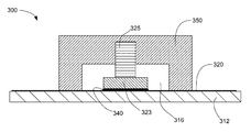
- FIG. 3 illustrates an example of a pneumatic flatwise tensile test (FWT) device.
- FIG. 4 illustrates an example implementation of a nondestructive test technique according to some implementations.
- FIG. 5 illustrates an example of a FWT test device for nondestructive testing according to some implementations.
- FIG. 6 compares two examples of a pull stub of a FWT test device.
- FIG. 7 illustrates an example of a pull stub of an FWT device according to an implementation.
- the presently disclosed techniques permit validation, by nondestructive ground test, that the bond strength between panel faceskin and honeycomb core of a flight panel meets or exceeds a specified criterion.
- the criterion may be related to the internal pressure that may develop within the panel as a result of launch vehicle assent plus a factor of safety.
- FIG. 2 an example of a pressure profile within a launch vehicle payload fairing during launch vehicle ascent is illustrated.
- pressure within the payload fairing decreases from one atmosphere to approximately a vacuum in approximately 130 seconds.
- the pressure differential between the panel interior and exterior may be as high as one atmosphere.
- a nondestructive bond strength test compatibility of faceskin bond strength with a pressure profile such as the one illustrated in FIG. 2 is demonstrated by a nondestructive bond strength test.
- a flatwise tensile (FWT) test device is employed.
- a suitable test apparatus may be adapted for nondestructive testing as detailed below from a pneumatic adhesion tensile testing instrument similar to the type available from, for example, the SEMicro Division of M.E. Taylor Engineering, Inc., of Rockville Md.
- FWT test devices are employed for destructive testing of various test articles.
- a pneumatic FWT test device 300 may destructively test the adhesive bond of a lamina 320 to a substrate 312 .
- a pull stub 323 is bonded by way of an adhesive 340 to the lamina 320 .
- the pull stub may include or be structurally secured to a threaded shank 325 which may engage a threaded bore in piston 350 .
- the lamina 320 may be a paint layer or similar thin coating applied to the substrate 312 .
- An ultimate strength of the bond between lamina 320 and substrate 312 may be determined by increasing a tensile load on the pull stub, until the bond breaks. Typically, the tensile load is increased by increasing pneumatic pressure within chamber 316 . By measuring the pressure within chamber 316 at which the bond breaks, the bond strength between lamina 320 and substrate 312 may be determined.
- the adhesive 340 typically an epoxy glue, must provide a bond between pull stub 323 and lamina 320 that is stronger than the bond between the lamina 320 and the substrate 312 .
- testing to verify that a bond strength between a panel faceskin and a core exceeds a minimum acceptable FWT strength may be accomplished using an FWT test apparatus in the manner illustrated in FIG. 4 .
- a method 400 may start, at block 410 by adhering a first surface of a sacrificial layer to a pull stub of the FWT test device.
- the sacrificial layer may be a double-sided tape, for example.
- the double-sided tape may be a foam adhesive tape that fails under a transverse tensile load of less than 40 PSI.
- the double-sided tape may be configured to be removable from the faceskin (by peeling, for example) without damaging the faceskin.
- the adhesion strength of at least one side of the double-sided tape may be selected such that it is greater than a first specified value and less than a second specified value.
- the first specified value may be related to the threshold value for FWT strength of the bond between the faceskin and the core.
- the second specified value may be related to the maximal FWT load that the faceskin may be expected to sustain without damage.
- margin factors may be applied to one or both of the minimum acceptable FWT strength and the maximal FWT load that the faceskin may be expected to sustain without damage.
- the sacrificial layer has been designed to reliably survive an FWT load of no less than 25 PSI and to reliably break at an FWT load of no greater than 50 PSI.
- Block 410 may include, referring now to FIG. 5 , adhering a first surface 541 of double back foam adhesive 540 to a pull stub 523 of a FWT test device 500 by way of a first adhesive interface between the first surface 541 and the pull stub 523 .
- the FWT test device 500 may include the pneumatic adhesion tensile testing instrument test apparatus referenced above.
- method 400 may continue, at block 420 , by adhering a second surface of the sacrificial layer, to the panel faceskin.
- Block 420 may include, referring again to FIG. 5 , adhering a second surface 542 of the sacrificial layer 540 to a faceskin 520 ( 1 ) of an equipment panel by way of a second adhesive interface between the second surface 542 and the faceskin 520 ( 1 ).
- the equipment panel includes honeycomb core 510 sandwiched between the first faceskin 520 ( 1 ) and a second faceskin 520 ( 2 ).
- method 400 may continue, at block 430 , by gradually increasing a FWT load on the panel faceskin.
- Block 430 may include, referring again to FIG. 5 , gradually increasing the FWT load by pressurizing piston arrangement 550 .
- piston arrangement 550 includes an upper plate 551 , lower plate 552 and gasket 555 .
- Gasket 555 which may be composed of silicon or similar elastomeric material, is disposed between upper plate 551 and lower plate 552 so as to form a sealed plenum into which pressurizing fluid may be introduced by way of input 553 .
- the pressurizing fluid may be a gas or hydraulic fluid, for example.
- the pressurizing fluid may be supplied to inlet 551 such that pressure is gradually increased within the sealed plenum, as a result of which a gradually increasing lifting force is exerted against upper plate 551 .
- the lifting force is transferred by way of shank 525 to pull stub 523 which in turn imparts a tensile load across sacrificial layer 540 .
- a determination may be made as to whether or not a separation of any one or more of the first adhesive interface, the second adhesive interface, and the sacrificial layer has occurred.
- the determination at block 440 may be made frequently or in a substantially continuous manner. If the determination at block 440 is that a separation has not occurred then the method returns to block 430 . On the other hand, if the determination at block 440 is that a separation has occurred that the method may proceed to block 450 , as described hereinbelow.
- a determination may be made as to whether or not separation of the faceskin from the core has occurred. The determination may be made on the basis of a visual inspection of the panel and/or of the sacrificial layer, for example. If the determination at block 450 is that separation of the faceskin from the core has occurred, it may be determined at block 470 that the faceskin and the core bond strength does not exceed the threshold value. On the other hand, if the determination at block 450 is that separation of the faceskin from the core has not occurred, it may be determined at block 460 at the faceskin and the core bond strength exceeds the threshold value.
- an FWT test procedure may be terminated upon separation of the faceskin 520 ( 1 ) from the honeycomb core 510 , or separation of the sacrificial layer 540 , whichever comes first.
- separation of sacrificial layer 540 may occur by way of either a break in the first adhesive interface between the sacrificial layer 540 and the pull stub 523 , or a break in the second adhesive interface between sacrificial layer 540 and the faceskin 520 ( 1 ), or by way of failure of the sacrificial layer 540 itself.
- the sacrificial layer 540 is a double back foam tape adhesive
- a strength of each of the first adhesive interface and the second adhesive interface may be greater than the strength of the foam tape material.
- the FWT test device 500 may be configured such that separation of sacrificial layer 540 occurs only at a tensile load that is (i) greater than the minimum acceptable FWT strength of the bond between the faceskin and the core and (ii) less than the maximal FWT load that the faces skin may be expected to sustain without damage.
- FIGS. 6 and 7 An example implementation is illustrated in FIGS. 6 and 7 .
- FIG. 6 compares a conventional pull stub 523 with a tapered pull stub 623 .
- FIG. 7 illustrates a specific implementation of a tapered pull stub where a first thickness t 1 , proximate to the perimeter of the interface area, is substantially less like than a second thickness t 2 near the central region.
- More uniform stress distribution may also be provided by selection of adhesive layer having relatively low modulus.
- a modulus of less than 500 PSI is within the contemplation of the present disclosure.
- the modulus may be approximately 75 PSI.
Abstract
Description
Claims (18)
Priority Applications (1)
| Application Number | Priority Date | Filing Date | Title |
|---|---|---|---|
| US14/448,744 US9523633B1 (en) | 2014-07-31 | 2014-07-31 | Nondestructive proof loading of honeycomb panels |
Applications Claiming Priority (1)
| Application Number | Priority Date | Filing Date | Title |
|---|---|---|---|
| US14/448,744 US9523633B1 (en) | 2014-07-31 | 2014-07-31 | Nondestructive proof loading of honeycomb panels |
Publications (1)
| Publication Number | Publication Date |
|---|---|
| US9523633B1 true US9523633B1 (en) | 2016-12-20 |
Family
ID=57538662
Family Applications (1)
| Application Number | Title | Priority Date | Filing Date |
|---|---|---|---|
| US14/448,744 Active 2034-11-17 US9523633B1 (en) | 2014-07-31 | 2014-07-31 | Nondestructive proof loading of honeycomb panels |
Country Status (1)
| Country | Link |
|---|---|
| US (1) | US9523633B1 (en) |
Cited By (4)
| Publication number | Priority date | Publication date | Assignee | Title |
|---|---|---|---|---|
| CN107831066A (en) * | 2017-10-27 | 2018-03-23 | 燕京啤酒(桂林漓泉)股份有限公司 | One kind judges the whether satisfactory method of corrugated case PUR joint sealing firmness |
| CN111238935A (en) * | 2020-01-23 | 2020-06-05 | 哈尔滨工业大学 | Stretching equipment with honeycomb strength online measurement function and measurement method thereof |
| CN111896394A (en) * | 2020-08-11 | 2020-11-06 | 郑州机械研究所有限公司 | Method and device for testing shear performance of sandwich structure |
| CN117054239A (en) * | 2023-10-09 | 2023-11-14 | 四川吉盛印铁有限公司 | Adhesive force testing device and method for surface coating of metal packaging plate |
Citations (7)
| Publication number | Priority date | Publication date | Assignee | Title |
|---|---|---|---|---|
| US2694924A (en) | 1954-11-23 | Xlaminated - -structure tester | ||
| US4491014A (en) | 1982-11-12 | 1985-01-01 | The United States Of America As Represented By The Secretary Of The Army | Bond testing apparatus |
| US4567758A (en) | 1984-05-14 | 1986-02-04 | Robert K. Fisher | Apparatus for testing the bond strength of materials |
| US6386027B1 (en) * | 1998-02-25 | 2002-05-14 | Ab Lorentzen & Wettre | Method and device for measuring z-directional tensile strength of paper or board |
| US7258760B2 (en) | 1998-12-02 | 2007-08-21 | Fuji Jukogyo Kabushiki Kaisha | Methods of forming honeycomb sandwich composite panels |
| US20120193015A1 (en) * | 2007-04-18 | 2012-08-02 | Nasa Headquarters | Specular coatings for composite structures |
| US8349104B2 (en) | 2008-07-21 | 2013-01-08 | United Technologies Corporation | Method and assembly for validating bond line |
-
2014
- 2014-07-31 US US14/448,744 patent/US9523633B1/en active Active
Patent Citations (7)
| Publication number | Priority date | Publication date | Assignee | Title |
|---|---|---|---|---|
| US2694924A (en) | 1954-11-23 | Xlaminated - -structure tester | ||
| US4491014A (en) | 1982-11-12 | 1985-01-01 | The United States Of America As Represented By The Secretary Of The Army | Bond testing apparatus |
| US4567758A (en) | 1984-05-14 | 1986-02-04 | Robert K. Fisher | Apparatus for testing the bond strength of materials |
| US6386027B1 (en) * | 1998-02-25 | 2002-05-14 | Ab Lorentzen & Wettre | Method and device for measuring z-directional tensile strength of paper or board |
| US7258760B2 (en) | 1998-12-02 | 2007-08-21 | Fuji Jukogyo Kabushiki Kaisha | Methods of forming honeycomb sandwich composite panels |
| US20120193015A1 (en) * | 2007-04-18 | 2012-08-02 | Nasa Headquarters | Specular coatings for composite structures |
| US8349104B2 (en) | 2008-07-21 | 2013-01-08 | United Technologies Corporation | Method and assembly for validating bond line |
Non-Patent Citations (5)
| Title |
|---|
| "PATTI Pneumatic Adhesion Tensile Testing Instrument", QUANTUM Series, Operator's Manual (Ditigital Model), retrieved on Oct. 27, 2014 from Internet at http://www.semicro.org/Quantum%20Digital%20Manual.pdf, 32 pages. |
| ASTM Designation: C297/C297M-04, "Standard Test Method for Flatwise Tensile Strength of Sandwich Constructions", May 2004. * |
| Callus et al., "F-111 Adhesive Bonded Repair Assessment Program (FABRAP)-Phase I Testing, Preliminary Results)", Unclassified, Australian Government Department of Defence, Defence Science and Technology Organization, Air Vehicles Division, DSTO-TN-1024, Aug. 2011, 79 pages. |
| Cen, "Aerospace Series-Non-metallic materials-Structural adhesives-Test method-Part 4: Metal-honeycomb core flatwise tensile test", European Committee for Standardization, EN 2243-4:2005(E), 2005, 14 pages. |
| Lee et al., "Assessment of Adhesive Bonded Repairs, A Thesis Submitted in Fulfillment of the Requirements for the Degree of Master of Engineering", School of Aerospace, Mechanical and Manufacturing Engineering, College of Science, Engineering and Health, RMIT University, Mar. 2013, 173 pages. |
Cited By (7)
| Publication number | Priority date | Publication date | Assignee | Title |
|---|---|---|---|---|
| CN107831066A (en) * | 2017-10-27 | 2018-03-23 | 燕京啤酒(桂林漓泉)股份有限公司 | One kind judges the whether satisfactory method of corrugated case PUR joint sealing firmness |
| CN107831066B (en) * | 2017-10-27 | 2021-01-12 | 燕京啤酒(桂林漓泉)股份有限公司 | Method for judging whether sealing firmness of hot melt adhesive of corrugated case meets requirements |
| CN111238935A (en) * | 2020-01-23 | 2020-06-05 | 哈尔滨工业大学 | Stretching equipment with honeycomb strength online measurement function and measurement method thereof |
| CN111896394A (en) * | 2020-08-11 | 2020-11-06 | 郑州机械研究所有限公司 | Method and device for testing shear performance of sandwich structure |
| CN111896394B (en) * | 2020-08-11 | 2023-04-07 | 郑州机械研究所有限公司 | Method and device for testing shear performance of sandwich structure |
| CN117054239A (en) * | 2023-10-09 | 2023-11-14 | 四川吉盛印铁有限公司 | Adhesive force testing device and method for surface coating of metal packaging plate |
| CN117054239B (en) * | 2023-10-09 | 2023-12-19 | 四川吉盛印铁有限公司 | Adhesive force testing device and method for surface coating of metal packaging plate |
Similar Documents
| Publication | Publication Date | Title |
|---|---|---|
| US9523633B1 (en) | Nondestructive proof loading of honeycomb panels | |
| US6823719B2 (en) | Method and apparatus to locally test pressure seal | |
| US8696843B1 (en) | Repair of acoustically treated structures | |
| US20100227117A1 (en) | Tapered patch for predictable bonded rework of composite structures | |
| Force | The importance of failure mode identification in adhesive bonded aircraft structures and repairs | |
| US9492975B2 (en) | Structural bonded patch with tapered adhesive design | |
| EP3137288A1 (en) | Structural bonded patch with tapered adhesive design | |
| Woerden et al. | Maintenance of glare structures and glare as riveted or bonded repair material | |
| Kwak et al. | An investigation of repair methods for delaminated composite laminate under flexural load | |
| Chester et al. | Adhesively bonded repairs to primary aircraft structure | |
| US6758924B1 (en) | Method of repairing cracked aircraft structures | |
| Matthews et al. | Application of supersonic particle deposition to enhance the structural integrity of aircraft structures | |
| US20160313286A1 (en) | Detecting damage in a composite panel without removing overlying insulation | |
| EP3069860B1 (en) | Method and assembly for inspecting a partially cured repair patch prior to installation | |
| CN107512403B (en) | Method for repairing broken glue of honeycomb panel of outfield of airplane | |
| Hart-Smith | Adhesive layer thickness and porosity criteria for bonded joints | |
| Wu et al. | Failure analysis of a frangible laminated composite canister cover | |
| RU2604114C1 (en) | Method of determining strength at cleavage of adhesive joint of cellular filler with skin in three-layer panel and device for its implementation | |
| US5142905A (en) | Overlapped test specimen fixture | |
| US10071817B2 (en) | Indication bolt for monitoring adhesive bonds in structural elements | |
| US11401052B2 (en) | High-visibility impact detection system and method of preparing the same | |
| Bakuckas Jr et al. | Fatigue and Residual Strength Performance of Bonded Repairs to Metallic Fuselage | |
| Denney et al. | Effect of disbond on fatigue behavior of cracked aluminum panel with bonded composite patch | |
| Chen et al. | Composite Fatigue Testing and Analysis of Sandwich Structures with Debonds | |
| Alawi et al. | Fatigue crack growth retardation by bonding patches |
Legal Events
| Date | Code | Title | Description |
|---|---|---|---|
| AS | Assignment |
Owner name: SPACE SYSTEMS/LORAL, LLC, CALIFORNIA Free format text: ASSIGNMENT OF ASSIGNORS INTEREST;ASSIGNOR:WARNOCK, RICHARD;REEL/FRAME:033449/0205 Effective date: 20140729 |
|
| STCF | Information on status: patent grant |
Free format text: PATENTED CASE |
|
| AS | Assignment |
Owner name: ROYAL BANK OF CANADA, AS THE COLLATERAL AGENT, CANADA Free format text: SECURITY INTEREST;ASSIGNORS:DIGITALGLOBE, INC.;MACDONALD, DETTWILER AND ASSOCIATES LTD.;MACDONALD, DETTWILER AND ASSOCIATES CORPORATION;AND OTHERS;REEL/FRAME:044167/0396 Effective date: 20171005 Owner name: ROYAL BANK OF CANADA, AS THE COLLATERAL AGENT, CAN Free format text: SECURITY INTEREST;ASSIGNORS:DIGITALGLOBE, INC.;MACDONALD, DETTWILER AND ASSOCIATES LTD.;MACDONALD, DETTWILER AND ASSOCIATES CORPORATION;AND OTHERS;REEL/FRAME:044167/0396 Effective date: 20171005 |
|
| AS | Assignment |
Owner name: ROYAL BANK OF CANADA, AS COLLATERAL AGENT, CANADA Free format text: AMENDED AND RESTATED U.S. PATENT AND TRADEMARK SECURITY AGREEMENT;ASSIGNOR:SPACE SYSTEMS/LORAL, LLC;REEL/FRAME:051258/0720 Effective date: 20191211 |
|
| AS | Assignment |
Owner name: WILMINGTON TRUST, NATIONAL ASSOCIATION, - AS NOTES Free format text: SECURITY AGREEMENT (NOTES);ASSIGNORS:DIGITALGLOBE, INC.;RADIANT GEOSPATIAL SOLUTIONS LLC;SPACE SYSTEMS/LORAL, LLC (F/K/A SPACE SYSTEMS/LORAL INC.);REEL/FRAME:051262/0824 Effective date: 20191211 Owner name: WILMINGTON TRUST, NATIONAL ASSOCIATION, - AS NOTES COLLATERAL AGENT, TEXAS Free format text: SECURITY AGREEMENT (NOTES);ASSIGNORS:DIGITALGLOBE, INC.;RADIANT GEOSPATIAL SOLUTIONS LLC;SPACE SYSTEMS/LORAL, LLC (F/K/A SPACE SYSTEMS/LORAL INC.);REEL/FRAME:051262/0824 Effective date: 20191211 |
|
| MAFP | Maintenance fee payment |
Free format text: PAYMENT OF MAINTENANCE FEE, 4TH YEAR, LARGE ENTITY (ORIGINAL EVENT CODE: M1551); ENTITY STATUS OF PATENT OWNER: LARGE ENTITY Year of fee payment: 4 |
|
| AS | Assignment |
Owner name: WILMINGTON TRUST, NATIONAL ASSOCIATION, AS NOTES COLLATERAL AGENT, CONNECTICUT Free format text: PATENT SECURITY AGREEMENT;ASSIGNOR:SPACE SYSTEMS/LORAL, LLC;REEL/FRAME:053866/0810 Effective date: 20200922 |
|
| AS | Assignment |
Owner name: ROYAL BANK OF CANADA, CANADA Free format text: SECURITY AGREEMENT;ASSIGNORS:MAXAR INTELLIGENCE INC.;MAXAR SPACE LLC;REEL/FRAME:060389/0720 Effective date: 20220614 |
|
| AS | Assignment |
Owner name: WILMINGTON TRUST, NATIONAL ASSOCIATION, TEXAS Free format text: SECURITY AGREEMENT;ASSIGNORS:MAXAR INTELLIGENCE INC.;MAXAR SPACE LLC;REEL/FRAME:060389/0782 Effective date: 20220614 |
|
| AS | Assignment |
Owner name: RADIANT GEOSPATIAL SOLUTIONS LLC, COLORADO Free format text: RELEASE BY SECURED PARTY;ASSIGNOR:WILMINGTON TRUST, NATIONAL ASSOCIATION;REEL/FRAME:060390/0282 Effective date: 20220614 Owner name: SPACE SYSTEMS/LORAL, LLC, CALIFORNIA Free format text: RELEASE BY SECURED PARTY;ASSIGNOR:WILMINGTON TRUST, NATIONAL ASSOCIATION;REEL/FRAME:060390/0282 Effective date: 20220614 Owner name: DIGITALGLOBE, INC., COLORADO Free format text: RELEASE BY SECURED PARTY;ASSIGNOR:WILMINGTON TRUST, NATIONAL ASSOCIATION;REEL/FRAME:060390/0282 Effective date: 20220614 |
|
| AS | Assignment |
Owner name: MAXAR SPACE LLC, CALIFORNIA Free format text: TERMINATION AND RELEASE OF PATENT SECURITY AGREEMENT - RELEASE OF REEL/FRAME 060389/0782;ASSIGNOR:WILMINGTON TRUST, NATIONAL ASSOCIATION, AS COLLATERAL AGENT;REEL/FRAME:063544/0074 Effective date: 20230503 Owner name: MAXAR INTELLIGENCE INC., COLORADO Free format text: TERMINATION AND RELEASE OF PATENT SECURITY AGREEMENT - RELEASE OF REEL/FRAME 060389/0782;ASSIGNOR:WILMINGTON TRUST, NATIONAL ASSOCIATION, AS COLLATERAL AGENT;REEL/FRAME:063544/0074 Effective date: 20230503 Owner name: MAXAR SPACE LLC, CALIFORNIA Free format text: TERMINATION AND RELEASE OF SECURITY INTEREST IN PATENTS AND TRADEMARKS - RELEASE OF REEL/FRAME 051258/0720;ASSIGNOR:ROYAL BANK OF CANADA, AS AGENT;REEL/FRAME:063542/0543 Effective date: 20230503 Owner name: MAXAR INTELLIGENCE INC., COLORADO Free format text: TERMINATION AND RELEASE OF SECURITY INTEREST IN PATENTS AND TRADEMARKS - RELEASE OF REEL/FRAME 051258/0720;ASSIGNOR:ROYAL BANK OF CANADA, AS AGENT;REEL/FRAME:063542/0543 Effective date: 20230503 Owner name: MAXAR SPACE LLC, CALIFORNIA Free format text: TERMINATION AND RELEASE OF SECURITY INTEREST IN PATENTS AND TRADEMARKS - RELEASE OF REEL/FRAME 044167/0396;ASSIGNOR:ROYAL BANK OF CANADA, AS AGENT;REEL/FRAME:063543/0001 Effective date: 20230503 Owner name: MAXAR INTELLIGENCE INC., COLORADO Free format text: TERMINATION AND RELEASE OF SECURITY INTEREST IN PATENTS AND TRADEMARKS - RELEASE OF REEL/FRAME 044167/0396;ASSIGNOR:ROYAL BANK OF CANADA, AS AGENT;REEL/FRAME:063543/0001 Effective date: 20230503 |
|
| AS | Assignment |
Owner name: SIXTH STREET LENDING PARTNERS, AS ADMINISTRATIVE AGENT, TEXAS Free format text: INTELLECTUAL PROPERTY SECURITY AGREEMENT;ASSIGNORS:MAXAR INTELLIGENCE INC. (F/K/A DIGITALGLOBE, INC.);AURORA INSIGHT INC.;MAXAR MISSION SOLUTIONS INC. ((F/K/A RADIANT MISSION SOLUTIONS INC. (F/K/A THE RADIANT GROUP, INC.));AND OTHERS;REEL/FRAME:063660/0138 Effective date: 20230503 |
|
| AS | Assignment |
Owner name: MAXAR INTELLIGENCE INC., COLORADO Free format text: RELEASE (REEL 060389/FRAME 0720);ASSIGNOR:ROYAL BANK OF CANADA;REEL/FRAME:063633/0431 Effective date: 20230503 Owner name: MAXAR SPACE LLC, CALIFORNIA Free format text: RELEASE (REEL 060389/FRAME 0720);ASSIGNOR:ROYAL BANK OF CANADA;REEL/FRAME:063633/0431 Effective date: 20230503 |
|
| AS | Assignment |
Owner name: MAXAR SPACE LLC, CALIFORNIA Free format text: CHANGE OF NAME;ASSIGNOR:SPACE SYSTEMS/LORAL, LLC;REEL/FRAME:063861/0016 Effective date: 20210101 |