US9522799B2 - Transport device and transport system - Google Patents
Transport device and transport system Download PDFInfo
- Publication number
- US9522799B2 US9522799B2 US14/709,545 US201514709545A US9522799B2 US 9522799 B2 US9522799 B2 US 9522799B2 US 201514709545 A US201514709545 A US 201514709545A US 9522799 B2 US9522799 B2 US 9522799B2
- Authority
- US
- United States
- Prior art keywords
- rollers
- roller
- speed
- process position
- sheet
- Prior art date
- Legal status (The legal status is an assumption and is not a legal conclusion. Google has not performed a legal analysis and makes no representation as to the accuracy of the status listed.)
- Active
Links
Images


Classifications
-
- B—PERFORMING OPERATIONS; TRANSPORTING
- B65—CONVEYING; PACKING; STORING; HANDLING THIN OR FILAMENTARY MATERIAL
- B65H—HANDLING THIN OR FILAMENTARY MATERIAL, e.g. SHEETS, WEBS, CABLES
- B65H5/00—Feeding articles separated from piles; Feeding articles to machines
- B65H5/06—Feeding articles separated from piles; Feeding articles to machines by rollers or balls, e.g. between rollers
- B65H5/068—Feeding articles separated from piles; Feeding articles to machines by rollers or balls, e.g. between rollers between one or more rollers or balls and stationary pressing, supporting or guiding elements
-
- B—PERFORMING OPERATIONS; TRANSPORTING
- B65—CONVEYING; PACKING; STORING; HANDLING THIN OR FILAMENTARY MATERIAL
- B65H—HANDLING THIN OR FILAMENTARY MATERIAL, e.g. SHEETS, WEBS, CABLES
- B65H5/00—Feeding articles separated from piles; Feeding articles to machines
- B65H5/06—Feeding articles separated from piles; Feeding articles to machines by rollers or balls, e.g. between rollers
- B65H5/062—Feeding articles separated from piles; Feeding articles to machines by rollers or balls, e.g. between rollers between rollers or balls
-
- B—PERFORMING OPERATIONS; TRANSPORTING
- B65—CONVEYING; PACKING; STORING; HANDLING THIN OR FILAMENTARY MATERIAL
- B65H—HANDLING THIN OR FILAMENTARY MATERIAL, e.g. SHEETS, WEBS, CABLES
- B65H7/00—Controlling article feeding, separating, pile-advancing, or associated apparatus, to take account of incorrect feeding, absence of articles, or presence of faulty articles
- B65H7/02—Controlling article feeding, separating, pile-advancing, or associated apparatus, to take account of incorrect feeding, absence of articles, or presence of faulty articles by feelers or detectors
-
- B—PERFORMING OPERATIONS; TRANSPORTING
- B65—CONVEYING; PACKING; STORING; HANDLING THIN OR FILAMENTARY MATERIAL
- B65H—HANDLING THIN OR FILAMENTARY MATERIAL, e.g. SHEETS, WEBS, CABLES
- B65H7/00—Controlling article feeding, separating, pile-advancing, or associated apparatus, to take account of incorrect feeding, absence of articles, or presence of faulty articles
- B65H7/20—Controlling associated apparatus
-
- H—ELECTRICITY
- H04—ELECTRIC COMMUNICATION TECHNIQUE
- H04N—PICTORIAL COMMUNICATION, e.g. TELEVISION
- H04N1/00—Scanning, transmission or reproduction of documents or the like, e.g. facsimile transmission; Details thereof
- H04N1/00567—Handling of original or reproduction media, e.g. cutting, separating, stacking
- H04N1/0057—Conveying sheets before or after scanning
- H04N1/00588—Conveying sheets before or after scanning to the scanning position
-
- H—ELECTRICITY
- H04—ELECTRIC COMMUNICATION TECHNIQUE
- H04N—PICTORIAL COMMUNICATION, e.g. TELEVISION
- H04N1/00—Scanning, transmission or reproduction of documents or the like, e.g. facsimile transmission; Details thereof
- H04N1/00567—Handling of original or reproduction media, e.g. cutting, separating, stacking
- H04N1/0057—Conveying sheets before or after scanning
- H04N1/00599—Using specific components
- H04N1/00602—Feed rollers
-
- H—ELECTRICITY
- H04—ELECTRIC COMMUNICATION TECHNIQUE
- H04N—PICTORIAL COMMUNICATION, e.g. TELEVISION
- H04N1/00—Scanning, transmission or reproduction of documents or the like, e.g. facsimile transmission; Details thereof
- H04N1/00567—Handling of original or reproduction media, e.g. cutting, separating, stacking
- H04N1/0057—Conveying sheets before or after scanning
- H04N1/00599—Using specific components
- H04N1/00615—Guiding elements, e.g. plates
-
- H—ELECTRICITY
- H04—ELECTRIC COMMUNICATION TECHNIQUE
- H04N—PICTORIAL COMMUNICATION, e.g. TELEVISION
- H04N1/00—Scanning, transmission or reproduction of documents or the like, e.g. facsimile transmission; Details thereof
- H04N1/04—Scanning arrangements, i.e. arrangements for the displacement of active reading or reproducing elements relative to the original or reproducing medium, or vice versa
- H04N1/047—Detection, control or error compensation of scanning velocity or position
- H04N1/0476—Indicating the scanning velocity
-
- H—ELECTRICITY
- H04—ELECTRIC COMMUNICATION TECHNIQUE
- H04N—PICTORIAL COMMUNICATION, e.g. TELEVISION
- H04N1/00—Scanning, transmission or reproduction of documents or the like, e.g. facsimile transmission; Details thereof
- H04N1/04—Scanning arrangements, i.e. arrangements for the displacement of active reading or reproducing elements relative to the original or reproducing medium, or vice versa
- H04N1/12—Scanning arrangements, i.e. arrangements for the displacement of active reading or reproducing elements relative to the original or reproducing medium, or vice versa using the sheet-feed movement or the medium-advance or the drum-rotation movement as the slow scanning component, e.g. arrangements for the main-scanning
- H04N1/121—Feeding arrangements
- H04N1/123—Using a dedicated sheet guide element
-
- B—PERFORMING OPERATIONS; TRANSPORTING
- B65—CONVEYING; PACKING; STORING; HANDLING THIN OR FILAMENTARY MATERIAL
- B65H—HANDLING THIN OR FILAMENTARY MATERIAL, e.g. SHEETS, WEBS, CABLES
- B65H2404/00—Parts for transporting or guiding the handled material
- B65H2404/10—Rollers
- B65H2404/14—Roller pairs
- B65H2404/143—Roller pairs driving roller and idler roller arrangement
-
- B—PERFORMING OPERATIONS; TRANSPORTING
- B65—CONVEYING; PACKING; STORING; HANDLING THIN OR FILAMENTARY MATERIAL
- B65H—HANDLING THIN OR FILAMENTARY MATERIAL, e.g. SHEETS, WEBS, CABLES
- B65H2404/00—Parts for transporting or guiding the handled material
- B65H2404/60—Other elements in face contact with handled material
- B65H2404/61—Longitudinally-extending strips, tubes, plates, or wires
- B65H2404/611—Longitudinally-extending strips, tubes, plates, or wires arranged to form a channel
- B65H2404/6111—Longitudinally-extending strips, tubes, plates, or wires arranged to form a channel and shaped for curvilinear transport path
-
- B—PERFORMING OPERATIONS; TRANSPORTING
- B65—CONVEYING; PACKING; STORING; HANDLING THIN OR FILAMENTARY MATERIAL
- B65H—HANDLING THIN OR FILAMENTARY MATERIAL, e.g. SHEETS, WEBS, CABLES
- B65H2511/00—Dimensions; Position; Numbers; Identification; Occurrences
- B65H2511/50—Occurence
- B65H2511/51—Presence
-
- B—PERFORMING OPERATIONS; TRANSPORTING
- B65—CONVEYING; PACKING; STORING; HANDLING THIN OR FILAMENTARY MATERIAL
- B65H—HANDLING THIN OR FILAMENTARY MATERIAL, e.g. SHEETS, WEBS, CABLES
- B65H2513/00—Dynamic entities; Timing aspects
- B65H2513/10—Speed
Definitions
- the present invention relates to a transport device and a transport system.
- a transport device including:
- rollers that are provided on a transporting path on which a sheet is transported in a transport direction and is subjected to a process at a process position, and transport the sheet which comes into contact with surfaces of the rollers in the transport direction by rotation of the rollers;
- first rollers that are provided closest to the process position on a downstream side in the transport direction of the process position;
- second rollers that are provided closest to the first rollers on an opposite side with respect to the process position in the transport direction when viewed from the first rollers;
- a driving unit that drives the first rollers and the second rollers to rotate so that a speed of a surface of the first roller is faster than a speed of a surface of the second roller at least while the sheet passes through the process position.
- FIG. 1 is a view illustrating the overall configuration of an image inspection system according to an exemplary embodiment
- FIG. 2 is a view illustrating the hardware configuration of a reading device
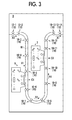
- FIG. 3 is a view illustrating the detailed configuration of a transport roller section
- FIG. 4 is an enlarged view of a roller section
- FIG. 5 is a view illustrating the functional configuration of a transport device
- FIG. 6 is a view illustrating an example of a surface speed table
- FIGS. 7A and 7B are views illustrating an example of a bend which occurs in a sheet
- FIGS. 8A and 8B are views illustrating an event which occurs in the sheet
- FIG. 9 is a view illustrating an example of a surface speed table of a modification example.
- FIG. 10 is a view illustrating a guide member of the modification example.
- FIG. 1 illustrates the overall configuration of an image inspection system 1 according to an exemplary embodiment.
- the image inspection system 1 includes an image forming apparatus 2 , a transport device 3 , and a post-processing device 4 .
- the transport device 3 is an example of a “transport device” of the invention.
- the devices are connected to each other by lines (not illustrated), and data is exchanged between the devices via the lines.
- the image forming apparatus 2 forms an image on a sheet such as paper, a cardboard, or an overhead projector (OHP) film in, for example, an electrophotographic method.
- the method of forming an image is not limited thereto, and an ink jet method, a thermal transfer method, or the like may also be employed.
- the image forming apparatus 2 forms images on both surfaces of a sheet, and discharges the sheet on which the images are formed to the transport device 3 .
- the image forming apparatus 2 transmits image data which is used for the image formation to the post-processing device 4 .
- the transport device 3 transports the sheet which is discharged from the image forming apparatus 2 to the post-processing device 4 along a transporting path B 1 .
- the transporting path B 1 is formed to extend from an entrance port B 2 on the image forming apparatus 2 side toward the post-processing device 4 side in a horizontal direction, bend downward in a vertical direction, and draw a “U” shape. Thereafter, the transporting path B 1 is bent in the horizontal direction and extends to an exit port B 3 on the post-processing device 4 side.
- the transport device 3 reads the images which are formed on both surfaces of the sheet while transporting the sheet. When the images are read, the transport device 3 transmits result data which indicates the result to the post-processing device 4 .
- the post-processing device 4 performs a predetermined post-process on the sheet discharged from the transport device 3 .
- the post-processing device 4 performs, as the post-process, a process of sorting sheets into sheets on which images are accurately formed and sheets on which images are not accurately formed.
- the post-processing device 4 calculates the degree of similarity between an image indicated by the image data transmitted from the image forming apparatus 2 and an image indicated by the result data transmitted from the transport device 3 , and determines that the image is accurately formed on the sheet when the calculated degree is greater than a threshold.
- the image inspection system 1 inspects the images formed on the sheet by the above-described function of each of the devices.
- FIG. 2 illustrates the hardware configuration of the transport device 3 .
- the transport device 3 includes a controller 5 , a first scanner 6 , a second scanner 7 , a motor section 8 , and a transport roller section 9 .
- the controller 5 includes, in addition to a central processing unit (CPU) and a random-access memory (RAM), a storage unit such as a read-only memory (ROM) or a hard disk.
- the CPU uses the RAM as a work area, and controls each unit by executing programs stored in the storage unit.
- the first scanner 6 and the second scanner 7 scan the sheet which is transported along the transporting path B 1 illustrated in FIG. 1 so as to perform a process of reading (hereinafter, referred to as “reading process”) the images formed on the sheet.
- reading process a process of reading
- the transport roller section 9 includes plural rollers, and each of the rollers is supported to rotate about its own rotation shaft. As the plural rollers rotate, the sheet which comes into contact with the surfaces of the rollers is transported in a transport direction A 1 illustrated in FIG. 1 .
- the motor section 8 includes motors, gears, and the like, and drives each of the plural rollers included in the transport roller section 9 so as to rotate. The motor section 8 is controlled by the controller 5 so as to rotate each of the rollers at a speed instructed by the controller 5 .
- FIG. 3 illustrates the specific configuration of the transport roller section 9 .
- the transport roller section 9 includes fourteen roller sections (referred to “roller sections 10 ” when the fourteen roller sections are not distinguished from each other) including roller sections 10 - 1 , 10 - 2 , . . . , 10 - 14 .
- the roller sections are provided to be sequentially arranged along the transporting path B 1 from the entrance port B 2 to the exit port B 3 .
- the distances between the adjacent roller sections 10 are shorter than the size of a sheet which is shortest in size in the transport direction A 1 such that any one of the roller sections 10 reliably comes into contact with the sheet.
- the first scanner 6 performs the reading process of reading the image by scanning the sheet at a first position C 1 of the transporting path B 1 .
- the first position C 1 is a position on the downstream side of the roller section 10 - 5 in the transport direction A 1 and on the upstream side of the roller section 10 - 6 in the transport direction A 1 .
- an opening which connects the transporting path B 1 to an external space is provided, and the first scanner 6 emits light through the opening and performs the reading process.
- the second scanner 7 performs the reading process of reading the image by scanning the sheet at a second position C 2 of the transporting path B 1 .
- the second position C 2 is a position on the downstream side of the roller section 10 - 10 in the transport direction A 1 and on the upstream side of the roller section 10 - 11 in the transport direction A 1 .
- an opening which connects the transporting path B 1 to an external space is provided, and the second scanner 7 emits light through the opening and performs the reading process.
- Both of the first position C 1 and the second position C 2 are positions (hereinafter, referred to as “process positions”) where the process is performed on the sheet transported on the transporting path B 1 . That is, in this exemplary embodiment, the process positions include the first position C 1 which is a first process position, and the second position C 2 which is a second process position positioned closer to the downstream side in the transport direction A 1 than the first position C 1 . In this exemplary embodiment, the distance between the first position C 1 and the second position C 2 in the transport direction A 1 is longer than the size of a largest sheet.
- FIG. 4 is an enlarged view of the roller section 10 .
- the roller section 10 includes a pair of rollers which are a roller 11 and a roller 12 (referred to as “rollers 100 ” in a case where the rollers are not distinguished from each other), and the roller 11 and the roller 12 form a nip area N 1 .
- the roller 11 rotates about a shaft 13 in a rotational direction A 11 indicated by arrow in the figure, and the roller 12 rotates about a shaft 14 in a rotational direction A 12 indicated by arrow in the figure.
- the roller section 10 is provided so that the nip area N 1 is present on the transporting path B 1 .
- the transporting path B 1 is formed by a guide member 20 .
- the guide member 20 is a member which guides the sheet along the transporting path B 1 .
- the roller 100 has a columnar (or cylindrical) shape.
- the roller 11 includes an outer peripheral surface 11 S
- the roller 12 includes an outer peripheral surface 12 S.
- the outer peripheral surfaces are referred to as “surfaces 110 of the rollers” in a case where the outer peripheral surfaces are not distinguished from each other.
- FIG. 4 a sheet 30 during passage through the nip area N 1 is illustrated. A first surface 31 of the sheet 30 comes into contact with the outer peripheral surface 11 S of the roller 11 in the nip area N 1 , and a second surface 32 comes into contact with the outer peripheral surface 12 S of the roller 12 in the nip area N 1 .
- the sheet 30 which comes into contact with the surface 110 (the outer peripheral surface 11 S or 12 S) of the roller 100 is transported in the transport direction A 1 .
- the plural rollers 100 described above are provided on the transporting path B 1 .
- the sheet 30 which comes into contact with the surface 110 of the rotating roller 100 is transported in the transport direction A 1 at a speed (hereinafter, referred to as a “surface speed”) at which the surface 110 is moved in the transport direction A 1 in the nip area N 1 .
- the surface speed is increased as the roller 100 rapidly rotates, and thus a speed (hereinafter, referred to as a “transport speed”) at which the sheet 30 is transported in the transport direction A 1 is also increased as the roller 100 rapidly rotates.
- the transport speed becomes lower than the surface speed when the sheet 30 is pulled toward the upstream side, and the transport speed becomes higher than the surface speed when the sheet 30 is pulled toward the downstream side.
- the pulling force is generated, for example, in a case where the surface speeds of the rollers 100 which are respectively included in the adjacent roller sections 10 are different from each other.
- the controller 5 of the transport device 3 illustrated in FIG. 2 controls each of the units by performing the programs, and thus the following functions are realized.
- FIG. 5 illustrates the functional configuration of the transport device 3 .
- the transport device 3 includes a first processor 301 , a second processor 302 , and a driving unit 303 .
- the first processor 301 performs a process on the sheet at the first position C 1 of the transporting path B 1 on which the sheet is transported in the transport direction A 1 .
- the second processor 302 performs a process on the sheet at the second position C 2 of the transporting path B 1 .
- Both of the first processor 301 and the second processor 302 in this exemplary embodiment perform the above-described reading process by scanning the sheet at a same speed. More specifically, the first processor 301 and the second processor 302 have light sources and image sensors, and perform the reading process by emitting light from the light sources toward the sheet and then receiving the reflected light by the image sensors.
- the first processor 301 notifies the driving unit 303 of whether or not the sheet is “during passage” through the first position C 1 .
- the first processor 301 stores the intensity of the reflected light which is received by the above-described image sensor when the sheet does not pass through the first position C 1 , notifies the driving unit 303 of the passage of the sheet in a case of receiving the reflected light having the intensity stored in the image sensor, and notifies the driving unit 303 of the absence of the sheet at the first position C 1 in a case of receiving the reflected light having another intensity.
- the driving unit 303 drives each of the above-described plural rollers 100 , that is, the plural rollers 100 which rotate to transport the sheets that come into contact with the surfaces of the rollers 100 in the transport direction A 1 such that the plural rollers 100 rotate about their own rotation shafts.
- the driving unit 303 drives first rollers 101 , second rollers 102 , third rollers 103 , and fourth rollers 104 among the plural rollers 100 in a specific method, which will be described later.
- the driving unit 303 drives, among the plural rollers 100 , the rollers 100 which are provided closest to the process positions on the downstream sides in the transport direction A 1 from the process positions (the first position C 1 and the second position C 2 in this exemplary embodiment) as the first rollers 101 .
- the term “closest to the process position” mentioned above indicates that the distance from the process position along the transporting path B 1 is shortest.
- the rollers 100 forming a pair even when one roller 100 is strictly closer to the process position than the other roller 100 , it is assumed that both of the rollers 100 are provided “closest to the process position”.
- the driving unit 303 drives, among the plural rollers 100 , the rollers 100 which are provided closest to the first rollers 101 on the opposite sides to the process positions in the transport direction A 1 when viewed from the first rollers 101 as the second rollers 102 .
- the driving unit 303 drives the rollers 100 which are provided closest to the process positions on the upstream sides from the process positions as the third rollers 103 , and drives the rollers 100 which are provided closest to the third rollers 103 on the opposite sides to the process positions when viewed from the third rollers 103 as the fourth rollers 104 .
- the first rollers 101 are the rollers 100 which are included in the roller section 10 - 6 and the roller section 10 - 11
- the second rollers 102 are the rollers 100 which are included in the roller section 10 - 7 and the roller section 10 - 12
- the third rollers 103 are the rollers 100 which are included in the roller section 10 - 5 and the roller section 10 - 10
- the fourth rollers 104 are the rollers 100 which are included in the roller section 10 - 4 and the roller section 10 - 9 .
- the driving unit 303 drives some of the first to fourth rollers in a more specific method. Specifically, the driving unit 303 drives, among the first rollers 101 , those (included in the roller section 10 - 6 ) which are provided on the downstream side of the first position C 1 that is the process position on the upstream side as fifth rollers 105 , and drives the second rollers 102 (included in the roller section 10 - 7 ) which are provided on the downstream side of the fifth roller 105 as sixth rollers 106 .
- the driving unit 303 drives, among the third rollers 103 , those (included in the roller section 10 - 10 ) which are provided on the upstream side of the second position C 2 that is the process position on the downstream side as seventh rollers 107 , and drives the fourth rollers 104 (included in the roller section 10 - 9 ) which are provided on the upstream side of the seventh roller 107 as eighth rollers 108 .
- the driving unit 303 stores a surface speed table in which the surface speed (the speed of the surface 110 of the roller 100 illustrated in FIG. 4 which moves in the transport direction A 1 in the nip area N 1 ) of each of the above-described rollers 100 when the rollers 100 are driven to rotate is determined.
- FIG. 6 illustrates an example of the surface speed table.
- the surface speed for each state of the sheet 30 at the first position C 1 is determined.
- “during passage” which indicates a state of passage through the first position C 1
- “before or after passage” which indicates a state of before passage or after passage are illustrated.
- the surface speeds of the rollers 100 included in the roller sections “ 10 - 1 to 10 - 5 ”, “ 10 - 6 ”, “ 10 - 7 ”, “ 10 - 8 ”, “ 10 - 9 ”, “ 10 - 10 ”, and “ 10 - 11 to 10 - 14 ” respectively correspond to “V 1 ”, “V 1 ”, “V 2 ”, “V 2 ”, “V 2 ”, “V 2 ” and “V 1 ” in the case of “during passage”, and respectively correspond to “V 1 ”, “V 3 ”, “V 3 ”, “V 3 ”, “V 1 ”, and “V 1 ” in the case of “before or after passage”.
- V 1 is a surface speed which is faster than V 2 and slower than V 3 . That is, a relationship of V 2 ⁇ V 1 ⁇ V 3 is formed.
- the driving unit 303 is notified of whether or not the sheet 30 is “during passage” through the first position C 1 by the first processor 301 .
- the driving unit 303 drives each of the rollers 100 to rotate at the surface speeds corresponding to “during passage” in the surface speed table when notified of the intent of during passage, and drives each of the rollers 100 to rotate at the surface speeds corresponding to “before or after passage” when notified of the intent of not “during passage”.
- the driving unit 303 drives the fifth rollers 105 (the pair of rollers 100 included in the roller section “ 10 - 6 ”) to rotate at the surface speed “V 1 ” “during passage” and to rotate at the surface speed “V 3 ” “before or after passage”, and drives the sixth rollers 106 (the pair of rollers 100 included in the roller section “ 10 - 7 ”) to rotate at the surface speed “V 2 ” “during passage” and to rotate at the surface speed “V 3 ” “before or after passage”.
- the driving unit 303 drives the fifth rollers 105 and the sixth rollers 106 so that the surface speed (“V 1 ” in this example) of the fifth roller 105 is faster than the surface speed (“V 2 ” in this example) of the sixth rollers 106 .
- the driving unit 303 drives the eighth rollers 108 (the pair of rollers 100 included in the roller section “ 10 - 9 ”) to rotate at the surface speed “V 2 ” “during passage” and to rotate at the surface speed “V 3 ” “before or after passage”, and drives the seventh rollers 107 (the pair of rollers 100 included in the roller section “ 10 - 10 ”) to rotate at the surface speed “V 2 ” “during passage” and to rotate at the surface speed “V 1 ” “before or after passage”.
- the driving unit 303 drives the seventh rollers 107 and the eighth rollers 108 so that the surface speed of the seventh roller 107 is set to the surface speed (“V 1 ” in this example) of the fifth roller 105 and the surface speed (“V 3 ” in this example) of the eighth roller 108 is faster than the surface speed of the seventh roller 107 .
- the driving unit 303 drives the fifth rollers 105 as the first rollers 101 and drives the sixth rollers 106 as the second rollers 102 and even in a case where the driving unit 303 drives the seventh rollers 107 as the first rollers 101 and drives the eighth rollers 108 as the second rollers 102 , the driving unit 303 drives the first rollers 101 and the second rollers 102 so that the surface speeds of the rollers (the fifth rollers 105 and the eighth rollers 108 ) on the upstream side among the first rollers 101 and the second rollers 102 are faster than the surface speeds of the rollers (the sixth rollers 106 and the seventh rollers 107 ) on the downstream side.
- the driving unit 303 drives the rollers 100 in this manner, on the transporting path B 1 interposed between the first rollers 101 and the second rollers 102 , the surface speed of the roller 100 on the downstream side is slow, and thus a bend occurs in the sheet 30 .
- FIGS. 7A and 7B illustrate an example of a bend which occurs in the sheet 30 .
- a bend 33 which occurs in a state where the fifth rollers 105 and the sixth rollers 106 are transporting the sheet 30 is illustrated.
- the bend 33 occurs on the transporting path B 1 on the downstream side of the fifth roller 105 and the upstream side of the sixth roller 106 .
- a bend 34 which occurs in a state where the seventh rollers 107 and the eighth rollers 108 are transporting the sheet 30 is illustrated.
- the bend 34 occurs on the transporting path B 1 on the downstream side of the eighth roller 108 and the upstream side of the seventh roller 107 .
- FIGS. 8A and 8B are views illustrating the event that occurs in the sheet 30 .
- a transport device 3 x which performs driving in the opposite manner to this exemplary embodiment is illustrated. That is, in the transport device 3 x , the surface speed of the sixth roller 106 is faster than the surface speed of the fifth roller 105 . Therefore, as illustrated in FIG. 8A , the sixth rollers 106 are in a state of exerting a force (a force exerted in a direction along arrow D 1 in the figure, hereinafter, referred to as “pulling force”) to pull the sheet 30 toward the downstream side in the transport direction A 1 .
- a force exerted in a direction along arrow D 1 in the figure, hereinafter, referred to as “pulling force” to pull the sheet 30 toward the downstream side in the transport direction A 1 .
- process position speed the speed (hereinafter, referred to as “process position speed”) of the sheet 30 at the first position C 1 in the transport direction A 1 is also increased. Therefore, before and after slipping occurs, the process position speed is changed. Particularly, as illustrated in FIG. 8A , at a time when a rear end 30 E of the sheet 30 passes through the roller section (roller section 10 - 5 in this example), the frictional force exerted by the roller section disappears, and thus the degree of slipping is increased due to the pulling force and the process position speed is more largely changed.
- the surface speed of the seventh roller 107 is faster than the surface speed of the eighth roller 108 . Therefore, as illustrated in FIG. 8B , the eighth rollers 108 are in a state of generating a force (pulling force exerted in a direction along arrow D 2 in the figure) to pull the sheet 30 toward the upstream side in the transport direction A 1 .
- a force pulling force exerted in a direction along arrow D 2 in the figure
- the transport speed of the seventh roller 107 is reduced, and thus the process position speed at the second position C 2 is also reduced. Even in this case, before and after slipping occurs, the process position speed is changed.
- the surface speed of the seventh roller 107 is set to the surface speed of the fifth roller 105 after the sheet passes through the first position C 1 , compared to the case where the surface speed of the seventh roller 107 is not changed, that is, the case where the transport speed of the sheet at the second position C 2 is always slower than the transport speed of the sheet at the first position C 1 , the time for passing the sheet through the transport device is reduced.
- the driving unit 303 since the driving unit 303 switches the surface speeds depending on whether or not the sheet 30 is “during passage” through the first position C 1 , variations in the speed of the sheet at the two process positions are suppressed.
- other methods may also be used.
- FIG. 9 illustrates an example of the surface speed table of this modification example.
- the surface speeds of the rollers 100 included in each of the roller sections 10 are determined in only one way.
- the surface speeds of the rollers 100 included in the roller sections “ 10 - 1 to 10 - 5 ”, “ 10 - 6 ”, “ 10 - 7 ”, “ 10 - 8 ”, “ 10 - 9 ”, “ 10 - 10 ”, and “ 10 - 11 to 10 - 14 ” respectively correspond to “V 1 ”, “V 1 ”, “V 2 ”, “V 2 ”, “V 4 ”, and “V 4 ”.
- V 4 is a surface speed which is slower than V 2 . That is, a relationship of V 4 ⁇ V 2 ⁇ V 1 is formed.
- the driving unit 303 drives the fifth rollers 105 and the sixth rollers 106 to rotate respectively at the surface speeds “V 1 ” and “V 2 ”, and drives the eighth rollers 108 and the seventh rollers 107 to rotate respectively at the surface speeds “V 2 ” and “V 4 ”. Even in this case, by the driving of the driving unit 303 , among the first rollers 101 and the second rollers 102 , the surface speeds of the rollers (the fifth rollers 105 and the eighth rollers 108 ) on the upstream side are faster than the surface speeds of the rollers (the sixth rollers 106 and the seventh rollers 107 ) on the downstream side.
- the surface speeds of the sixth roller 106 and the surface speed of the eighth roller 108 are equal to V 2 .
- the surface speed of the eighth roller 108 may be faster than the surface speed of the sixth roller 106 .
- the driving unit 303 of this modification example drives the fifth rollers 105 , the sixth rollers 106 , the seventh rollers 107 , and the eighth rollers 108 so that the surface speed of the fifth roller 105 is faster than the surface speed of the sixth roller 106 , the surface speed of the sixth roller 106 is equal to or faster than the surface speed of the eighth roller 108 , and the surface speed of the eighth roller 108 is faster than the surface speed of the seventh roller 107 .
- the second processor 302 performs the reading process by scanning the sheet 30 at the second position C 2 at a slower speed than that of the first processor 301 . More specifically, when the process position speed at the first position C 1 is X times the process position speed at the second position C 2 , the second processor 302 performs the reading process so that the scanning speed of the first processor 301 in the reading process is X times the scanning speed of the second processor 302 in the reading process.
- the ratio between the process position speeds at the first position C 1 and the second position C 2 is represented by the ratio (hereinafter, referred to as “surface speed ratio”) of the surface speed of the seventh roller 107 to the surface speed of the fifth rollers 105 in a case where slipping of the fifth rollers 105 and the seventh rollers 107 on the sheet 30 does not occur. Therefore, the second processor 302 may perform the reading process at a scanning speed obtained by multiplying the scanning speed of the first processor 301 in the reading process by the surface speed ratio. In this modification example, even when the surface speeds of the rollers 100 are not switched, variations in the speed of the sheet is suppressed as in the above-described exemplary embodiment.
- the sheet is allowed to bend by changing the surface speeds of the first roller 101 and the second roller 102 .
- the sheet may be allowed to easily bend by the shape of the guide member.
- FIG. 10 illustrates a guide member 20 a of this modification example.
- the guide member 20 a guides the sheet from the rollers (the first rollers 101 in this example) on the upstream side to the rollers (the second rollers 102 in this example) on the downstream side among the first rollers 101 and the second rollers 102 along the transporting path B 1 .
- the guide member 20 a includes a collision surface 21 a which is provided at a position where a tip end 30 F of the sheet 30 transported by the first rollers 101 which are the rollers on the upstream side collides with the guide member.
- the collision surface 21 a is a surface which includes a portion that intersects a virtual plane which comes into contact with the surface 110 of the first roller 101 in the nip area N 1 of the first rollers 101 .
- the collision surface 21 a and the sheet 30 form an angle ⁇ 1 when the tip end 30 F of the sheet 30 collides with the collision surface 21 a .
- ⁇ 1 is too close to 90°, there is concern that the sheet 30 may be bent and block the transporting path B 1 , and thus the collision surface 21 a may be formed so that ⁇ 1 is, for example, equal to or less than 45°.
- the tip end 30 F of the sheet 30 which collides with the collision surface 21 a advances along the collision surface 21 a in a direction away from the above-described virtual plane, and as a result, a bend occurs in the sheet 30 .
- the collision surface 21 a is provided, compared to a case where the collision surface 21 a is not provided in a path to the rollers 100 on the downstream side, the sheet 30 which is transported by the rollers 100 on the upstream side is easily bent.
- a space E 1 which is wider than a space E 2 formed on the downstream side of the collision surface 21 a is formed on the upstream side of the collision surface 21 a .
- the spaces E 1 and E 2 are illustrated which are respectively enclosed by dotted lines.
- the width of the transporting path B 1 the width of the space E 2 is about L 2 at any position.
- the width of the transporting path B 1 is equal to or greater than L 2 at any position and is L 1 which is about 1.5 times L 2 at the maximum.
- the bent portion is less likely to come into contact with the guide member 20 a . Therefore, slipping at a position where the first rollers 101 and the sheet 30 come into contact with each other, for example, due to the frictional force generated by the contact with the guide member 20 a , is less likely to occur.
- the second surface 32 side swells.
- the width of the transporting path B 1 in the space E 1 on the second surface 32 side is greater than that on the first surface 31 side. Accordingly, for example, compared to a case where the relationship of the widths of the transporting path B 1 is opposite (the width on the second surface 32 side is smaller than that on the first surface 31 side), the sheet 30 and the guide member 20 a are less likely to come into contact with each other.
- the process of reading the images of the sheet is performed.
- the process is not limited thereto, for example, a process of ejecting ink onto a sheet may be performed, and a secondary transfer process may also be performed during image formation in the electrophotographic method.
- a processor having a function of performing such a process may be provided to perform the process on the sheet at the process position.
- variations in the transport speed at the process position are suppressed and thus the accuracy of the process is enhanced.
- the transport device includes the two processors.
- the transport device is not limited thereto and may include a single processor or may also include three or more processors.
- a processor included in an external device may perform a process on the sheet.
- any processor may be used as long as the processor performs the process on the sheet transported on the transporting path at the process position. Even when any processor is used, since the driving unit 303 drives the rollers 100 as described above, variations in the speed of the sheet at the process position may be suppressed as in the exemplary embodiment.
- the rollers 100 included in the roller section 10 - 6 illustrated in FIG. 3 are driven in the above-described specific method.
- the rollers 100 included in the roller section 10 - 11 may also be driven in the same method.
- the rollers 100 included in the roller section 10 - 12 may be driven in the same method as that of the rollers 100 included in the roller section 10 - 7 .
- a bend occurs in the sheet on the downstream side of the roller section 10 - 11 , and thus the roller section 10 - 12 does not pull the sheet which passes through the second position C 2 in the transport direction A 1 .
- driving may be performed in the specific method on both of the upstream side and the downstream side of the second position C 2 .
- the rollers 100 included in the roller section 10 - 10 illustrated in FIG. 3 are driven by the above-described specific method.
- the rollers 100 included in the roller section 10 - 5 may be driven in the same method.
- the rollers 100 included in the roller section 10 - 4 may be driven in the same method as that of the rollers 100 included in the roller section 10 - 9 .
- a bend occurs in the sheet on the upstream side of the roller section 10 - 5 , and thus the roller section 10 - 4 does not pull the sheet which passes through the first position C 1 in the opposite direction to the transport direction A 1 .
- driving may be performed by the specific method on both the upstream side and the downstream side of the first position C 1 .
- the sheet is transported on the U-shaped transporting path B 1 .
- the transporting path is not limited thereto, and the sheet may be transported on a linear transporting path or the sheet may be transported on a transporting path having other shapes.
- the transporting path may also be formed along any of the vertical direction, the horizontal direction, and a direction inclined therefrom.
- the invention is considered as the transport device and the image inspection system provided with the transport device.
- the invention may be considered as an inspection device or an image reading device which outputs reading results in a case where the processor performs the process of reading an image, and the invention may be considered as an image forming apparatus in a case where the processor performs a process of ejecting ink or a secondary transfer process.
- the invention may also be applied to any device which performs a process on a transported sheet and in which it is desirable to stabilize the transport speed at which the sheet is transported at the process position.
Landscapes
- Engineering & Computer Science (AREA)
- Multimedia (AREA)
- Signal Processing (AREA)
- Mechanical Engineering (AREA)
- Delivering By Means Of Belts And Rollers (AREA)
- Counters In Electrophotography And Two-Sided Copying (AREA)
- Control Or Security For Electrophotography (AREA)
Abstract
Description
Claims (16)
Applications Claiming Priority (2)
| Application Number | Priority Date | Filing Date | Title |
|---|---|---|---|
| JP2014-227363 | 2014-11-07 | ||
| JP2014227363A JP6435788B2 (en) | 2014-11-07 | 2014-11-07 | Transport device |
Publications (2)
| Publication Number | Publication Date |
|---|---|
| US20160130101A1 US20160130101A1 (en) | 2016-05-12 |
| US9522799B2 true US9522799B2 (en) | 2016-12-20 |
Family
ID=55911664
Family Applications (1)
| Application Number | Title | Priority Date | Filing Date |
|---|---|---|---|
| US14/709,545 Active US9522799B2 (en) | 2014-11-07 | 2015-05-12 | Transport device and transport system |
Country Status (3)
| Country | Link |
|---|---|
| US (1) | US9522799B2 (en) |
| JP (1) | JP6435788B2 (en) |
| CN (1) | CN106183467B (en) |
Families Citing this family (4)
| Publication number | Priority date | Publication date | Assignee | Title |
|---|---|---|---|---|
| JP6213499B2 (en) * | 2015-02-26 | 2017-10-18 | コニカミノルタ株式会社 | Image forming system |
| JP6706434B2 (en) * | 2016-07-12 | 2020-06-10 | 株式会社リコー | Image reading apparatus and image forming apparatus |
| CN109805813A (en) * | 2019-02-20 | 2019-05-28 | 北京拓翼普众科技发展有限公司 | Intelligent and economical paper delivery system and method for public health facilities |
| US11952235B2 (en) * | 2021-04-09 | 2024-04-09 | Fujifilm Business Innovation Corp. | Image forming system and charge eliminating apparatus |
Citations (10)
| Publication number | Priority date | Publication date | Assignee | Title |
|---|---|---|---|---|
| US5157520A (en) * | 1987-09-30 | 1992-10-20 | Sharp Kabushiki Kaisha | Device for transporting documents |
| US5540426A (en) * | 1993-03-10 | 1996-07-30 | Minolta Camera Kabushiki Kaisha | Method of feeding sheets and device for the same |
| US6338481B1 (en) * | 1999-03-24 | 2002-01-15 | Minolta Co., Ltd. | Sheet decurling apparatus |
| US20060197997A1 (en) | 2005-03-02 | 2006-09-07 | Canon Kabushiki Kaisha | Image reading apparatus, and image expansion and contraction correcting method |
| JP2006270819A (en) | 2005-03-25 | 2006-10-05 | Sharp Corp | Image reading device |
| US20100109229A1 (en) * | 2008-11-06 | 2010-05-06 | Canon Kabushiki Kaisha | Sheet conveying apparatus and image forming apparatus |
| US20100226667A1 (en) * | 2009-03-06 | 2010-09-09 | Fuji Xerox Co., Ltd. | Image forming apparatus |
| US20130250279A1 (en) * | 2012-03-26 | 2013-09-26 | Konica Minolta Business Technologies, Inc. | Gloss Measuring Device and Image Forming Device Including Same |
| US20150061209A1 (en) | 2013-08-30 | 2015-03-05 | Fuji Xerox Co., Ltd. | Conveyance apparatus and conveyance system |
| US20160023857A1 (en) * | 2014-07-28 | 2016-01-28 | Fuji Xerox Co., Ltd. | Recording sheet transport device and image reading device |
Family Cites Families (6)
| Publication number | Priority date | Publication date | Assignee | Title |
|---|---|---|---|---|
| JP2760648B2 (en) * | 1990-09-25 | 1998-06-04 | シャープ株式会社 | Sheet resist equipment |
| JPH10194530A (en) * | 1996-12-28 | 1998-07-28 | Canon Inc | Image forming device |
| JP2010217691A (en) * | 2009-03-18 | 2010-09-30 | Fuji Xerox Co Ltd | Image forming apparatus, image processor, and program |
| JP5505612B2 (en) * | 2009-10-29 | 2014-05-28 | セイコーエプソン株式会社 | Material transport apparatus and image processing apparatus |
| JP2012116608A (en) * | 2010-11-30 | 2012-06-21 | Canon Electronics Inc | Method and device for transporting sheet, and sheet processing device |
| JP5983253B2 (en) * | 2012-09-28 | 2016-08-31 | ブラザー工業株式会社 | Image forming apparatus |
-
2014
- 2014-11-07 JP JP2014227363A patent/JP6435788B2/en not_active Expired - Fee Related
-
2015
- 2015-05-12 US US14/709,545 patent/US9522799B2/en active Active
- 2015-07-09 CN CN201510400749.XA patent/CN106183467B/en active Active
Patent Citations (12)
| Publication number | Priority date | Publication date | Assignee | Title |
|---|---|---|---|---|
| US5157520A (en) * | 1987-09-30 | 1992-10-20 | Sharp Kabushiki Kaisha | Device for transporting documents |
| US5540426A (en) * | 1993-03-10 | 1996-07-30 | Minolta Camera Kabushiki Kaisha | Method of feeding sheets and device for the same |
| US6338481B1 (en) * | 1999-03-24 | 2002-01-15 | Minolta Co., Ltd. | Sheet decurling apparatus |
| US20060197997A1 (en) | 2005-03-02 | 2006-09-07 | Canon Kabushiki Kaisha | Image reading apparatus, and image expansion and contraction correcting method |
| JP2006245927A (en) | 2005-03-02 | 2006-09-14 | Canon Inc | Image reading apparatus and image expansion / contraction correction method |
| JP2006270819A (en) | 2005-03-25 | 2006-10-05 | Sharp Corp | Image reading device |
| US20100109229A1 (en) * | 2008-11-06 | 2010-05-06 | Canon Kabushiki Kaisha | Sheet conveying apparatus and image forming apparatus |
| US20100226667A1 (en) * | 2009-03-06 | 2010-09-09 | Fuji Xerox Co., Ltd. | Image forming apparatus |
| US20130250279A1 (en) * | 2012-03-26 | 2013-09-26 | Konica Minolta Business Technologies, Inc. | Gloss Measuring Device and Image Forming Device Including Same |
| US20150061209A1 (en) | 2013-08-30 | 2015-03-05 | Fuji Xerox Co., Ltd. | Conveyance apparatus and conveyance system |
| JP2015048189A (en) | 2013-08-30 | 2015-03-16 | 富士ゼロックス株式会社 | Conveyance system |
| US20160023857A1 (en) * | 2014-07-28 | 2016-01-28 | Fuji Xerox Co., Ltd. | Recording sheet transport device and image reading device |
Also Published As
| Publication number | Publication date |
|---|---|
| US20160130101A1 (en) | 2016-05-12 |
| JP2016088717A (en) | 2016-05-23 |
| JP6435788B2 (en) | 2018-12-12 |
| CN106183467A (en) | 2016-12-07 |
| CN106183467B (en) | 2019-04-05 |
Similar Documents
| Publication | Publication Date | Title |
|---|---|---|
| US20240294348A1 (en) | Medium feeding device and image reading apparatus | |
| US8056897B2 (en) | Moving sensor for sheet edge position measurement | |
| US9522799B2 (en) | Transport device and transport system | |
| US9212020B2 (en) | Sheet processing apparatus and image forming system | |
| US9280118B2 (en) | Image forming apparatus | |
| JP5904222B2 (en) | Paper folding apparatus and image forming apparatus | |
| JP5718621B2 (en) | Sheet conveying apparatus and information reading apparatus | |
| JP7148865B2 (en) | MEDIUM CONVEYING DEVICE, IMAGE READING DEVICE, AND CONVEYING CONTROL METHOD | |
| JPH10120253A (en) | Sheet conveying apparatus, image reading apparatus and image forming apparatus including the same | |
| US20140205355A1 (en) | Media skew reduction | |
| CN111252590B (en) | Medium transport device, image reading device, transport control method | |
| US20150355592A1 (en) | Printing apparatus and control method | |
| JP5702212B2 (en) | Sheet conveying apparatus and information reading apparatus | |
| US20250172892A1 (en) | Image forming apparatus | |
| JP2007302383A (en) | Paper folding device | |
| JP5149234B2 (en) | Cross transfer device | |
| US12049379B2 (en) | Medium feeding apparatus, image reading apparatus, and medium feeding method | |
| US12358306B2 (en) | Printing apparatus and control method | |
| JP2023000427A (en) | Sheet folding device, image forming device and image forming system | |
| JP2012217912A (en) | Medium accumulation apparatus and medium treatment apparatus | |
| JP2014005095A (en) | Document conveyance device and image forming apparatus including the same | |
| WO2010119786A1 (en) | Cross conveying device | |
| JP2014237520A (en) | Sheet transport device and image forming apparatus | |
| KR20050078893A (en) | A apparatus for preventing jam of a duplex printer and a duplex printer adopting the same |
Legal Events
| Date | Code | Title | Description |
|---|---|---|---|
| AS | Assignment |
Owner name: FUJI XEROX CO., LTD., JAPAN Free format text: ASSIGNMENT OF ASSIGNORS INTEREST;ASSIGNORS:HACHISUGA, MASAKI;FURUYA, TAKAO;MAKIDA, SEIGO;AND OTHERS;REEL/FRAME:035616/0449 Effective date: 20150428 |
|
| STCF | Information on status: patent grant |
Free format text: PATENTED CASE |
|
| MAFP | Maintenance fee payment |
Free format text: PAYMENT OF MAINTENANCE FEE, 4TH YEAR, LARGE ENTITY (ORIGINAL EVENT CODE: M1551); ENTITY STATUS OF PATENT OWNER: LARGE ENTITY Year of fee payment: 4 |
|
| AS | Assignment |
Owner name: FUJIFILM BUSINESS INNOVATION CORP., JAPAN Free format text: CHANGE OF NAME;ASSIGNOR:FUJI XEROX CO., LTD.;REEL/FRAME:058287/0056 Effective date: 20210401 |
|
| MAFP | Maintenance fee payment |
Free format text: PAYMENT OF MAINTENANCE FEE, 8TH YEAR, LARGE ENTITY (ORIGINAL EVENT CODE: M1552); ENTITY STATUS OF PATENT OWNER: LARGE ENTITY Year of fee payment: 8 |