US9520440B2 - Imaging device and method of manufacturing the same - Google Patents
Imaging device and method of manufacturing the same Download PDFInfo
- Publication number
- US9520440B2 US9520440B2 US14/719,462 US201514719462A US9520440B2 US 9520440 B2 US9520440 B2 US 9520440B2 US 201514719462 A US201514719462 A US 201514719462A US 9520440 B2 US9520440 B2 US 9520440B2
- Authority
- US
- United States
- Prior art keywords
- region
- seal ring
- insulating film
- film
- photoresist
- Prior art date
- Legal status (The legal status is an assumption and is not a legal conclusion. Google has not performed a legal analysis and makes no representation as to the accuracy of the status listed.)
- Expired - Fee Related
Links
Images


Classifications
-
- H01L27/14685—
-
- H01L27/14687—
-
- H—ELECTRICITY
- H10—SEMICONDUCTOR DEVICES; ELECTRIC SOLID-STATE DEVICES NOT OTHERWISE PROVIDED FOR
- H10F—INORGANIC SEMICONDUCTOR DEVICES SENSITIVE TO INFRARED RADIATION, LIGHT, ELECTROMAGNETIC RADIATION OF SHORTER WAVELENGTH OR CORPUSCULAR RADIATION
- H10F39/00—Integrated devices, or assemblies of multiple devices, comprising at least one element covered by group H10F30/00, e.g. radiation detectors comprising photodiode arrays
- H10F39/011—Manufacture or treatment of image sensors covered by group H10F39/12
- H10F39/024—Manufacture or treatment of image sensors covered by group H10F39/12 of coatings or optical elements
-
- H—ELECTRICITY
- H10—SEMICONDUCTOR DEVICES; ELECTRIC SOLID-STATE DEVICES NOT OTHERWISE PROVIDED FOR
- H10F—INORGANIC SEMICONDUCTOR DEVICES SENSITIVE TO INFRARED RADIATION, LIGHT, ELECTROMAGNETIC RADIATION OF SHORTER WAVELENGTH OR CORPUSCULAR RADIATION
- H10F39/00—Integrated devices, or assemblies of multiple devices, comprising at least one element covered by group H10F30/00, e.g. radiation detectors comprising photodiode arrays
- H10F39/011—Manufacture or treatment of image sensors covered by group H10F39/12
- H10F39/026—Wafer-level processing
-
- H—ELECTRICITY
- H10—SEMICONDUCTOR DEVICES; ELECTRIC SOLID-STATE DEVICES NOT OTHERWISE PROVIDED FOR
- H10F—INORGANIC SEMICONDUCTOR DEVICES SENSITIVE TO INFRARED RADIATION, LIGHT, ELECTROMAGNETIC RADIATION OF SHORTER WAVELENGTH OR CORPUSCULAR RADIATION
- H10F39/00—Integrated devices, or assemblies of multiple devices, comprising at least one element covered by group H10F30/00, e.g. radiation detectors comprising photodiode arrays
- H10F39/80—Constructional details of image sensors
- H10F39/803—Pixels having integrated switching, control, storage or amplification elements
- H10F39/8037—Pixels having integrated switching, control, storage or amplification elements the integrated elements comprising a transistor
-
- H—ELECTRICITY
- H10—SEMICONDUCTOR DEVICES; ELECTRIC SOLID-STATE DEVICES NOT OTHERWISE PROVIDED FOR
- H10F—INORGANIC SEMICONDUCTOR DEVICES SENSITIVE TO INFRARED RADIATION, LIGHT, ELECTROMAGNETIC RADIATION OF SHORTER WAVELENGTH OR CORPUSCULAR RADIATION
- H10F39/00—Integrated devices, or assemblies of multiple devices, comprising at least one element covered by group H10F30/00, e.g. radiation detectors comprising photodiode arrays
- H10F39/80—Constructional details of image sensors
- H10F39/805—Coatings
- H10F39/8053—Colour filters
-
- H—ELECTRICITY
- H10—SEMICONDUCTOR DEVICES; ELECTRIC SOLID-STATE DEVICES NOT OTHERWISE PROVIDED FOR
- H10F—INORGANIC SEMICONDUCTOR DEVICES SENSITIVE TO INFRARED RADIATION, LIGHT, ELECTROMAGNETIC RADIATION OF SHORTER WAVELENGTH OR CORPUSCULAR RADIATION
- H10F39/00—Integrated devices, or assemblies of multiple devices, comprising at least one element covered by group H10F30/00, e.g. radiation detectors comprising photodiode arrays
- H10F39/80—Constructional details of image sensors
- H10F39/806—Optical elements or arrangements associated with the image sensors
- H10F39/8063—Microlenses
-
- H—ELECTRICITY
- H10—SEMICONDUCTOR DEVICES; ELECTRIC SOLID-STATE DEVICES NOT OTHERWISE PROVIDED FOR
- H10F—INORGANIC SEMICONDUCTOR DEVICES SENSITIVE TO INFRARED RADIATION, LIGHT, ELECTROMAGNETIC RADIATION OF SHORTER WAVELENGTH OR CORPUSCULAR RADIATION
- H10F39/00—Integrated devices, or assemblies of multiple devices, comprising at least one element covered by group H10F30/00, e.g. radiation detectors comprising photodiode arrays
- H10F39/80—Constructional details of image sensors
- H10F39/811—Interconnections
-
- H10W42/00—
-
- H01L27/14621—
-
- H01L27/14625—
-
- H01L27/14627—
Definitions
- the present invention relates to an imaging device and a method of manufacturing the same.
- the present invention is preferably applicable to an imaging device having a waveguide and a method of manufacturing such an imaging device.
- seal rings are so formed as to continuously enclose the chip from circumference.
- the seal rings are formed together with a plug for the chip and wirings or the like. Being stacked sequentially, eventually, the seal rings are built like a wall continuously enclosing the chip.
- an imaging device having a CMOS (Complementary Metal Oxide Semiconductor) image sensor.
- CMOS Complementary Metal Oxide Semiconductor
- Such an imaging device is adapted to an electronic still camera, a smart phone, etc.
- a pixel region where pixel elements such as a photodiode converting incident light into an electric charge are formed and a peripheral circuit region where a peripheral circuit processing the electric charge converted by the pixel element as an electric signal is formed.
- the seal ring is so formed as to enclose the pixel region and the peripheral circuit region.
- an imaging device in which a waveguide leading the light to a photodiode is provided.
- the waveguide is formed when a hole is formed by subjecting etching treatment to insulating films including an interlayer film etc. covering the pixel region and filling the hole with a predetermined gap fill member.
- Patent Document 1 As an example of a document in which a semiconductor device having a seal ring is disclosed.
- Patent Documents 2 and 3 as examples of documents in which an imaging device having a waveguide is disclosed.
- a hole to be a waveguide In a step where a hole to be a waveguide is formed, first, a predetermined region of a pixel region is exposed, and a pattern of a photoresist covering a peripheral circuit region and a seal ring region in which a seal ring is disposed is formed. Next, by subjecting etching treatment to the insulating film using the photoresist as an etching mask, the hole to be a waveguide is formed.
- the pixel region In the pixel region, it is necessary to guide light as efficiently as possible to the pixel element (photodiode) through the waveguide. Therefore, part of the insulating film located in the pixel region is removed. For this reason, at the time of forming the hole to be the waveguide, the pixel region becomes lower in height than seal ring region in particular. That is, a level of the seal ring region becomes higher than the pixel region and, in the seal ring region, the photoresist becomes thinner as compared with the pixel region.
- the imaging device has a waveguide and includes: a seal ring region; a pixel region having the waveguide therein and a peripheral circuit region; and an insulating film.
- a first concave portion is formed in a region located on the outward side of a seal ring along the seal ring.
- a position of a surface of the insulating film located right above the seal ring is referred to as a first position.
- a position of the surface of the insulating film located in a first concave portion is referred to as a second position.
- a position of the surface of the insulating film located in a direction departing from the first concave portion for the outside of the seal ring region is referred to as a third position. Then, the second position is lower than the first position in height. Further, the third position is lower than the first position but higher than the second position.
- a manufacturing method of an imaging device is a manufacturing method of an imaging device having a waveguide and, in particular, includes the following steps.
- An insulating film is so formed over a semiconductor substrate as to cover a pixel region, a pad electrode, and a seal ring.
- etching treatment is subjected to the exposed first and second regions of the insulating film.
- a region including the first and second regions of the insulating film is covered, and a pattern of a second photoresist for exposing a third region of the insulating film located in the pixel region is formed. Then, using the second photoresist as an etching mask, by subjecting etching treatment to the exposed third region of the insulating film, a waveguide holding hole is formed in the pixel region.
- an imaging device of one embodiment it is possible to prevent deterioration of a surface of a portion of an insulating film covering a seal ring formed in a seal ring region.
- FIG. 1 is a plan view showing one example of a device layout of an imaging device according to First Embodiment
- FIG. 2 is a cross-sectional view taken along line II-II shown in FIG. 1 according to the embodiment;
- FIG. 3 is a flow chart showing an outline of a manufacturing method of the imaging device according to the embodiment.
- FIG. 4 is a partial cross-sectional view showing one step of the manufacturing method of the imaging device according to the embodiment
- FIG. 5 is a partial cross-sectional view showing a step after the step shown in FIG. 4 according to the embodiment
- FIG. 6 is a partial cross-sectional view showing a step after the step shown in FIG. 5 according to the embodiment
- FIG. 7 is a partial cross-sectional view showing a step after the step shown in FIG. 6 according to the embodiment.
- FIG. 8 is a partial cross-sectional view showing a step after the step shown in FIG. 7 according to the embodiment.
- FIG. 9 is a partial cross-sectional view showing a step after the step shown in FIG. 8 according to the embodiment.
- FIG. 10 is a partial cross-sectional view showing a step after the step shown in FIG. 9 according to the embodiment.
- FIG. 11 is a partial cross-sectional view showing a step after the step shown in FIG. 10 according to the embodiment.
- FIG. 12 is a partial cross-sectional view showing a step after the step shown in FIG. 11 according to the embodiment.
- FIG. 13 is a partial cross-sectional view showing a step after the step shown in FIG. 12 according to the embodiment
- FIG. 14 is a partial cross-sectional view showing a step after the step shown in FIG. 13 according to the embodiment.
- FIG. 15 is a partial cross-sectional view showing a step after the step shown in FIG. 14 according to the embodiment.
- FIG. 16 is a partial cross-sectional view showing a step after the step shown in FIG. 15 according to the embodiment.
- FIG. 17 is a partial cross-sectional view showing a step after the step shown in FIG. 16 according to the embodiment.
- FIG. 18 is a partial cross-sectional view showing a step after the step shown in FIG. 17 according to the embodiment.
- FIG. 19 is a partial cross-sectional view showing a step after the step shown in FIG. 18 according to the embodiment.
- FIG. 20 is a partial cross-sectional view showing a step after the step shown in FIG. 19 according to the embodiment.
- FIG. 21 is a partial cross-sectional view showing a step after the step shown in FIG. 20 according to the embodiment.
- FIG. 22 is a partial cross-sectional view showing a step after the step shown in FIG. 21 according to the embodiment.
- FIG. 23 is a partial cross-sectional view showing a step after the step shown in FIG. 22 according to the embodiment.
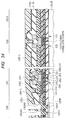
- FIG. 24 is a partial cross-sectional view showing a step after the step shown in FIG. 23 according to the embodiment.
- FIG. 25 is a partial cross-sectional view showing a step after the step shown in FIG. 24 according to the embodiment.
- FIG. 26 is a partial cross-sectional view showing a step after the step shown in FIG. 25 according to the embodiment.
- FIG. 27 is a partial cross-sectional view showing a step after the step shown in FIG. 26 according to the embodiment.
- FIG. 28 is a partial cross-sectional view showing a step after the step shown in FIG. 27 according to the embodiment.
- FIG. 29 is a partial cross-sectional view showing a step after the step shown in FIG. 28 according to the embodiment.
- FIG. 30 is a partial cross-sectional view showing a step after the step shown in FIG. 29 according to the embodiment.
- FIG. 31 is a partial cross-sectional view showing one step of a manufacturing method of an imaging device according to a comparative example
- FIG. 32 is a partial cross-sectional view showing a step after the step shown in FIG. 31 ;
- FIG. 33 is a partial cross-sectional view showing a step after the step shown in FIG. 32 ;
- FIG. 34 is a partial cross-sectional view showing a step after the step shown in FIG. 33 ;
- FIG. 35 is a partial cross-sectional view showing a step after the step shown in FIG. 34 ;
- FIG. 36 is a partial cross-sectional view showing a step after the step shown in FIG. 35 ;
- FIG. 37 is a partial cross-sectional view showing a step after the step shown in FIG. 36 ;
- FIG. 38 is a partial cross-sectional view showing a step after the step shown in FIG. 37 ;
- FIG. 39 is a partial cross-sectional view explaining a problem of the imaging device according to the comparative example.
- FIG. 40 is a first partial cross-sectional view explaining the operational advantage according to the embodiment.
- FIG. 41 is a second partial cross-sectional view explaining the operational advantage according to the embodiment.
- FIG. 42 is a third partial cross-sectional view explaining the operational advantage according to the embodiment.
- FIG. 43 is a partial cross-sectional view of an imaging device of a modification with respect to the embodiment.
- FIG. 44 is a partial cross-sectional view showing one step of a manufacturing method of an imaging device according to Second Embodiment.
- FIG. 45 is a partial cross-sectional view showing a step after the step shown in FIG. 44 according to the embodiment.
- FIG. 46 is a partial cross-sectional view showing a step after the step shown in FIG. 45 according to the embodiment.
- FIG. 47 is a partial cross-sectional view showing a step after the step shown in FIG. 46 according to the embodiment.
- FIG. 48 is a partial cross-sectional view showing a step after the step shown in FIG. 47 according to the embodiment.
- FIG. 49 is a partial cross-sectional view showing a step after the step shown in FIG. 48 according to the embodiment.
- FIG. 50 is a partial cross-sectional view showing a step after the step shown in FIG. 49 according to the embodiment.
- FIG. 51 is a partial cross-sectional view showing a step after the step shown in FIG. 50 according to the embodiment.
- FIG. 52 is a first partial cross-sectional view explaining the operational advantage according to the embodiment.
- FIG. 53 is a second partial cross-sectional view explaining the operational advantage according to the embodiment.
- FIG. 54 is the first partial cross-sectional view explaining the operational advantage according to the embodiment.
- FIG. 55 is a partial cross-sectional view of an imaging device of a modification with respect to the embodiment.
- FIG. 1 in the imaging device IS, there is arranged a pixel region PE where pixel elements such as a photodiode converting incident light into an electric charge are formed.
- pixel region PE Around the pixel region PE, there is arranged a peripheral circuit region PC where a peripheral circuit processing the electric charge converted by the pixel element as an electrical signal is formed.
- seal ring region SR where seal rings are so formed as to continuously enclose the pixel region PE and the peripheral circuit region PC from circumference.
- the pixel region PE, the peripheral circuit region PC, and the seal ring region SR are defined by forming an element-isolation insulating film EI over the semiconductor substrate SUB.
- a pixel element DTE is formed in the pixel region PE.
- the pixel element DTE includes a photodiode for converting light into an electric charge and a transfer transistor etc. for transferring the electric charge. Also, for simplifying the drawing, the portion concerned is outlined by a dotted line.
- a transistor PT etc. processing the electric charge converted by the pixel element DTE as an electrical signal are formed in the peripheral circuit region PC.
- a first insulating film IF 1 is formed as a contact interlayer insulating film.
- a contact plug PG is formed in the peripheral circuit region PC and a seal ring SRPG is comprised of the same film (material) as a film to be the contact plug PG in the seal ring region SR through the first insulating film IF 1 .
- a second insulating film IF 2 is so formed as to cover the first insulating film IF 1 .
- the second insulating film IF 2 includes a SiCN film (carbon-doped silicon nitride film) and a TEOS (Tetra Ethyl Ortho Silicate) oxide film.
- a first wiring M 1 is formed in a groove formed in the second insulating film IF 2 .
- a seal ring SRM 1 is comprised of the same film (material) as a film to be the first wiring M 1 .
- a third insulating film IF 3 is so formed as to cover the first wiring M 1 etc.
- the third insulating film IF 3 includes a SiCN film and a SiCO film (carbon-doped silicon oxide film) as stopper films and a SiOC film as a Low-k film.
- a second wiring M 2 is formed in a groove etc. formed in the third insulating film IF 3 .
- a seal ring SRM 2 is comprised of the same film (material) as a film to be the second wiring M 2 .
- a fourth insulating film IF 4 is so formed as to cover the second wiring M 2 etc.
- the fourth insulating film IF 4 includes a SiCN film and a SiCO film as stopper films and a SiOC film as a Low-k film.
- a third wiring M 3 is formed in the peripheral circuit region PC, in a groove etc. formed in the fourth insulating film IF 4 .
- a seal ring SRM 3 is comprised of the same film (material) as a film to be the third wiring M 3 .
- a fifth insulating film IF 5 is so formed as to cover the third wiring M 3 or the like.
- the fifth insulating film IF 5 includes a SiCN film and a SiCO film as stopper films and a TEOS film (having a thickness of about 200 nm) to be a hard mask.
- a pixel hole PEH is formed by removing the fourth insulating film IF 4 and the fifth insulating film IF 5 .
- a first waveguide holding hole WGH 1 penetrating the third insulating film IF 3 and the second insulating film IF 2 , and reaching the midway of a depth of the first insulating film IF 1 .
- a silicon nitride film SN is so formed as to fill the first waveguide holding hole WGH 1 and the pixel hole PEH and to cover the fifth insulating film IF 5 .
- a first waveguide WG 1 is formed by a portion of the silicon nitride film SN embedded in the first waveguide holding hole WGH 1 .
- a TEOS film TE 1 (having a thickness of about 200 nm) is so formed as to cover the silicon nitride film SN.
- pad electrodes PD are formed in holes formed in the TEOS film TE 1 , the silicon nitride film SN, and the fifth insulating film IF 5 .
- a seal ring SRPD is comprised of the same film (material) as a film to be the pad electrode PD.
- a TEOS film TE 2 is so formed as to cover the pad electrode PD etc. and, further, a TEOS film.
- TE 3 (having a thickness of about 100 nm) is so formed as to cover the TEOS film TE 2 .
- a second waveguide holding hole WGH 2 penetrating the TEOS film TE 3 and the TEOS film TE 2 and reaching the first waveguide WG 1 .
- a gap fill member FM of a coating type is so formed as to fill the second waveguide holding hole WGH 2 and to cover the TEOS film TE 3 .
- a sixth insulating film IF 6 is so formed as to cover the gap fill member FM.
- a second waveguide WG 2 is formed by a portion of the gap fill member FM embedded in the second waveguide holding hole WGH 2 .
- a color filter CF and a micro lens ML are disposed right above the second waveguide WG 2 .
- a dummy color filter DCF and a dummy micro lens DML are arranged on the side of the peripheral circuit region PC.
- the imaging device IS according to the present embodiment is configured as above.
- the imaging device IS described above after formation of the TEOS film TE 2 covering the pad electrode PD and the seal ring SRPD, by subjecting dry etching treatment to a portion covering the pad electrode PD and a portion covering the seal ring SRPD at the same time, the level difference of the peripheral circuit region PC and the level difference of the seal ring region SR are reduced.
- the manufacturing method of the imaging device IS will be described.
- step S 1 by forming an element-isolation insulating film over the semiconductor substrate, the pixel region, the peripheral circuit region, and the seal ring region or the like are defined.
- step S 2 in the pixel region, pixel elements such as a photodiode and a transistor are formed in the pixel region and peripheral circuit elements such as a transistor are formed in the peripheral circuit region.
- step S 3 an insulating film (interlayer film) is so formed as to cover the pixel elements and the peripheral circuit elements or the like.
- step S 4 a plug is formed in the peripheral circuit region and a seal ring is formed in the seal ring region.
- a multilayer copper wiring is formed in the peripheral circuit region and a seal ring is formed in the seal ring region.
- step S 6 the pixel region is made thinner by removing the insulating film etc. located in the pixel region (height reduction).
- step S 7 a first waveguide is formed in the pixel region.
- step S 8 a pad electrode is formed in the peripheral circuit region and a seal ring is formed in the seal ring region.
- step S 9 an insulating film (passivation film) is so formed as to cover the pad electrode.
- step S 10 etching treatment is performed to reduce a level difference of the insulating film (passivation film).
- step S 11 by subjecting the etching treatment to the insulating film (passivation film), a second waveguide holding hole is formed in the pixel region. There are cases in which a second waveguide is formed and in which a color filter is formed in the second waveguide holding hole.
- step S 12 when the color filter and the micro lens are formed in the pixel region, principal parts of the imaging device are completed.
- predetermined pixel elements DTE including a photodiode and a transfer transistor or the like are formed.
- the photodiode has a function of converting light entering from the outside to an electric charge.
- the transfer transistor has a function of transferring the electric charge converted by the photodiode to another predetermined element.
- elements such as a transistor PT are formed in the peripheral circuit region PC.
- the transistor PT or the like has a function of processing the electric charge converted by the pixel element DTE as an electrical signal.
- a first insulating film IF 1 is formed over the semiconductor substrate SUB, so as to cover the pixel element DTE and the transistor PT or the like, as a contact interlayer film.
- a contact hole PGH penetrating the first insulating film IF 1 and reaching the transistor PT is formed in the peripheral circuit region PC.
- a seal ring hole SRH 1 is so formed as to continuously enclose the pixel region PE and the peripheral circuit region PC.
- a predetermined conductive film (not shown) is so formed over the first insulating film IF 1 as to fill the contact hole PGH and the seal ring hole SRH 1 .
- the contact plug PG is formed in the contact hole PGH and the seal ring SRPG is formed in the seal ring hole SRH 1 .
- the contact plug PG is electrically coupled to the transistor PT.
- the seal ring SRPG is formed like a wall continuously enclosing the pixel region PE and the peripheral circuit region PC. In addition, in this imaging device, the seal ring is of a three-fold configuration.
- a second insulating film IF 2 is so formed as to cover the first insulating film IF 1 .
- the second insulating film IF 2 at least a SiCN film and a TEOS film are laminated.
- a pattern of a photoresist RP 1 for forming a wiring groove and a seal ring hole is formed.
- a wiring groove M 1 H for exposing the contact plug PG is formed in the peripheral circuit region PC.
- a seal ring hole SRH 2 exposing the seal ring SRPG is formed. Subsequently, the photoresist RP 1 is removed.
- a copper film MF 1 is so formed over the second insulating film IF 2 as to fill the wiring groove M 1 H and the seal ring hole SRH 2 .
- a barrier film and a copper seed layer are formed in advance.
- a portion of the copper film MF 1 located over an upper surface of the second insulating film IF 2 is removed by performing chemical mechanical polishing.
- a first wiring M 1 is formed in the wiring groove M 1 H.
- a seal ring SRM 1 is formed in a seal ring hole SRH 2 .
- the seal ring SRM 1 is formed like a wall which is in contact with an upper surface of the seal ring SRPG and continuously encloses the pixel region PE and the peripheral circuit region PC.
- a third insulating film IF 3 is so formed as to cover the first wiring M 1 and the seal ring SRM 1 .
- the third insulating film IF 3 for instance, a SiCN film and a SiCO film as stopper films and a SiOC film as a Low-k film are laminated.
- a first cap film LN 1 is so formed as to cover the third insulating film IF 3 .
- a TEOS film is formed.
- a pattern of a photoresist RP 2 for forming a via hole and a seal ring hole is formed.
- a via hole V 1 H for exposing the first wiring M 1 is formed by subjecting etching treatment to the third insulating film IF 3 etc. in the peripheral circuit region PC.
- a seal ring hole SRH 3 for exposing the seal ring SRM 1 is formed.
- the photoresist RP 2 is removed.
- a photoresist (not shown) is newly applied and, by subjecting etch back treatment to the photoresist, leaving portions of the photoresist located in the via hole V 1 H and the seal ring hole SRH 3 , other portions of the photoresist are removed.
- a pattern of a photoresist RP 3 for forming a wiring groove and a seal ring hole is formed.
- a pattern of a photoresist RP 3 for forming a wiring groove and a seal ring hole is formed.
- a SiOC film as a Low-k film in the third insulating film IF 3 a wiring groove M 2 H is formed in the peripheral circuit region PC.
- a seal ring hole SRH 4 is formed.
- the photoresist RP 3 is removed.
- a copper film MF 2 is so formed over the third insulating film IF 3 as to fill the wiring groove M 2 H, the via hole V 1 H, and the seal ring holes SRH 3 and SRH 4 .
- a barrier film and a copper seed layer are formed in advance.
- a portion of the copper film MF 2 located over an upper surface of the third insulating film IF 3 is removed by chemical mechanical polishing.
- a via V 1 is formed in the via hole V 1 H and a second wiring M 2 is formed in the wiring groove M 2 H (see FIG. 11 ).
- a seal ring SRM 2 is formed in the seal ring holes SRH 3 and SRH 4 (see FIG. 11 ).
- the seal ring SRM 2 is formed like a wall which is in contact with an upper surface of the seal ring SRM 1 and continuously encloses the pixel region PE and the peripheral circuit region PC. At this time, the first cap film LN 1 is removed.
- a fourth insulating film IF 4 is so formed as to cover the second wiring M 2 and the seal ring SRM 2 .
- the fourth insulating film IF 4 for instance, a SiCN film and a SiCO film as stopper films and a SiOC film as a Low-k film are laminated.
- a second cap film LN 2 is so formed as to cover the fourth insulating film IF 4 .
- a TEOS film is formed.
- a pattern of a photoresist RP 4 for forming a via hole and a seal ring hole is formed.
- a via hole V 2 H for exposing the second wiring M 2 is formed by subjecting etching treatment to the fourth insulating film IF 4 etc. in the peripheral circuit region PC.
- a seal ring hole SRH 5 for exposing the seal ring SRM 2 is formed.
- the photoresist RP 4 is removed.
- a photoresist (not shown) is newly applied and, by subjecting etch back treatment to the photoresist, leaving portions of the photoresist located in the via hole V 2 H and the seal ring hole SRH 5 , other portions of the photoresist are removed.
- a pattern of a photoresist RP 5 for forming a wiring groove and a seal ring hole is formed.
- a photoresist R 53 as an etching mask, by subjecting etching treatment to a SiOC film as a Low-k film in the fourth insulating film IF 4 , a wiring groove M 3 H is formed in the peripheral circuit region PC.
- a seal ring hole SRH 6 is formed in the seal ring region SR.
- the photoresist RP 5 is removed.
- a copper film MF 3 is so formed over the fourth insulating film IF 4 as to fill the wiring groove M 3 H, the via hole V 2 H, and the seal ring holes SRH 5 and SRH 6 .
- a barrier film and a copper seed layer are formed in advance.
- a portion of the copper film MF 3 located over an upper surface of the fourth insulating film IF 4 is removed by performing chemical mechanical polishing.
- a via V 2 is formed in the via hole V 2 H and a third wiring M 3 is formed in the wiring groove M 3 H (see FIG. 15 ).
- a seal ring SRM 3 is formed in the seal ring holes SRH 5 and SRH 6 (see FIG. 15 ).
- the seal ring SRM 3 is formed like a wall which is in contact with an upper surface of the seal ring SRM 2 and continuously encloses the pixel region PE and the peripheral circuit region PC.
- the second cap film LN 2 is also removed.
- a fifth insulating film IF 5 is so formed as to cover the third wiring M 3 and the seal ring SRM 3 .
- the fifth insulating film IF 5 for instance, the SiCN film and the SiCO film as stopper films and the TEOS film as a hard mask are laminated.
- a pattern of the photoresist (not shown) exposing the pixel region PE and covering other regions is formed.
- by performing etching treatment using the photoresist as an etching mask leaving portions of the TEOS film located in the peripheral circuit region PC and the seal ring region SR or the like, a portion of the TEOS film located in the pixel region PE is removed.
- etching treatment using the remaining portion etc. of the TEOS film as an etching mask (hard mask)
- a portion of the SiOC film (Low-k film) of the fourth insulating film IF 4 located in the pixel region PE is removed, and a pixel hole PEH is formed in the pixel region PE.
- the process of thinning the insulating film etc. located over the pixel element DTE is performed (height reduction).
- a photoresist RP 6 for forming a first waveguide holding hole is formed.
- a first waveguide holding hole WGH 1 is formed in the pixel region PE.
- the photoresist RP 6 is removed.
- a thick silicon nitride film SN is so formed as to fill the first waveguide holding hole WGH 1 .
- a photoresist RP 8 is so applied as to cover the silicon nitride film SN.
- etch back treatment is subjected to the photoresist RP 8 .
- the silicon nitride film SN is flattened (see FIG. 19 ).
- a first waveguide WG 1 is formed.
- a SiCN film having a thickness of about 30 nm
- a SiCO film having a thickness of about 30 nm
- liner films there are laminated a SiCN film (having a thickness of about 30 nm) and a SiCO film (having a thickness of about 30 nm) as liner films, a TEOS film (having a thickness of about 100 nm), and a silicon nitride film SN (having a thickness of about 400 nm) over the seal ring SRM 3 .
- the TEOS film TE 1 (having a thickness of about 200 nm) is so formed as to cover the silicon nitride film SN.
- a pattern of a photoresist RP 9 for forming a pad hole and a seal ring hole is formed.
- a pad hole PDH for exposing a third wiring M 3 is formed in the peripheral circuit region PC.
- a seal ring hole SRH 7 for exposing the seal ring SRM 3 is formed.
- the photoresist RP 9 is removed.
- a titanium film having a thickness of about 10 nm
- a titanium nitride film having a thickness of about 50 nm
- an aluminum film MF 4 having a thickness of about 600 nm is formed by the sputtering method.
- a pattern of a photoresist RP 10 for forming a pad electrode and a seal ring is formed.
- a pad electrode PD electrically coupled to the third wiring M 3 is formed in the pad hole PDH.
- a seal ring SRPD is formed in the seal ring hole SRH 7 .
- the seal ring SRPD is formed like a wall which is in contact with an upper surface of the seal ring SRM 3 and continuously encloses the pixel region PE and the peripheral circuit region PC. Subsequently, the photoresist RP 10 is removed.
- a TEOS film TE 2 (having a thickness of about 750 nm) is formed as a passivation film.
- a process to reduce the level differences of the TEOS film TE 2 is performed. As shown in FIG. 23 , a TEOS film TE 2 (having a thickness of about 750 nm) is formed as a passivation film.
- a lithography process there are exposed a portion of the TEOS film TE 2 covering the pad electrode PD in the peripheral circuit region PC and a portion of the TEOS film TE 2 covering the seal ring SRPD in the seal ring region SR, respectively, and a pattern of a photoresist RP 11 covering a portion of the TEOS film TE 2 located in another region is formed.
- the TEOS film TE 2 located in a region of about 1 ⁇ m from an edge of the seal ring SRPD on the peripheral circuit region PC side to the peripheral circuit region PC side. Also, there is exposed a portion of the TEOS film TE 2 located in a region of about 3 ⁇ m from an edge of the seal ring SRPD on the scribe region SCR side to the scribe region SCR side.
- an exposed portion of about 550 nm of the TEOS film TE 2 is removed.
- the dry etching treatment for instance, there is known reactive ion etching with use of fluorocarbon gas (CHF 3 , C 2 F 6 ). Subsequently, the photoresist RP 11 is removed.
- fluorocarbon gas CHF 3 , C 2 F 6
- each of the level differences of the TEOS film TE 2 located in the peripheral circuit region PC (pad electrode PD) and the seal ring region SR (seal ring SRPD) with respect to the TEOS film TE 2 located in the pixel region PE is reduced.
- grooves are formed on the sides of the peripheral circuit region PC and the scribe region SCR, respectively, along the seal ring SRPD. A width of the groove formed on the side of the scribe region SCR is greater than a width of the groove formed on the side of the peripheral circuit region PC.
- a TEOS film TE 3 (having a width of about 100 nm) is further formed so as to cover the TEOS film TE 2 .
- a pattern of a photoresist RP 12 for forming a second waveguide holding hole is formed.
- a second waveguide holding hole WGH 2 for exposing the first waveguide WG 1 in the pixel region PE is formed.
- the level difference (height) of the TEOS film TE 2 located in the seal ring region SR is reduced, even if the surface of the photoresist RP 12 is removed to some extent by the etching treatment, it is possible to prevent the surface of the TEOS film TE 2 from being exposed. After the second waveguide holding hole WGH 2 has been formed, the photoresist RP 12 is removed.
- a pattern of a photoresist RP 13 for exposing the pad electrode PD is formed.
- FIG. 28 using the photoresist RP 13 as an etching mask, by subjecting etching treatment to the TEOS film TE 3 and the TEOS film TE 2 , a surface of the pad electrode PD is exposed.
- FIG. 29 by removing the photoresist RP 13 , the second waveguide holding hole WGH 2 or the like is exposed.
- an insulating gap fill member FM of a coating type is so formed as to fill the second waveguide holding hole WGH 2 and to cover the TEOS film TE 3 .
- a second waveguide WG 2 in communication with the first waveguide WG 1 is formed.
- a color filter CF and a dummy color filter DCF are formed over the gap fill member FM.
- a sixth insulating film IF 6 is so formed as to cover the color filter CF and the dummy color filter DCF.
- a micro lens ML corresponding to the color filter CF and a dummy micro lens DML corresponding to the dummy color filter DCF are formed.
- a hole HP for exposing a surface of the pad electrode PD is formed.
- the manufacturing method of the imaging device described above it is possible to prevent the surface of the TEOS film TE 2 from getting rough by etching treatment during the formation of the second waveguide holding hole.
- an explanation will be made while comparing with an imaging device according to a comparative example.
- steps until formation of the TEOS film covering the pad electrode are the same as the manufacturing steps of First Embodiment described above, which will be explained briefly.
- a character “C” is affixed before each of first letters of the reference characters concerned.
- a pixel region CPE, a peripheral circuit region CPC, and a seal ring region CSR or the like are defined by forming an element-isolation insulating film CEI over the semiconductor substrate CSUB.
- a predetermined pixel element CDTE is formed in the pixel region CPE and elements such as a transistor CPT are formed in the peripheral circuit region CPC.
- a contact plug CPG is formed in the peripheral circuit region CPC and a seal ring CSRPG is formed in the seal ring region CSR.
- a first wiring CM 1 is formed in the peripheral circuit region CPC and a seal ring CSRM 1 is formed in the seal ring region CSR.
- a via CV 1 and s second wiring CM 2 are formed in the peripheral circuit region CPC and a seal ring CSRM 2 is formed in the seal ring region CSR.
- a via CV 2 and a third wiring CM 3 are formed in the peripheral circuit region CPC and a seal ring CSRM 3 is formed in the seal ring region CSR.
- a pad electrode CPD is formed in the peripheral circuit region CPC and a seal ring CSRPD is formed in the seal ring region CSR.
- a TEOS film CTE 2 (having a thickness of about 750 nm) is so formed as to cover the pad electrode CPD and the seal ring CSRPD.
- a lithography process a portion of the TEOS film CTE 2 covering the pad electrode PD is exposed, and a pattern of a photoresist CRP 11 covering other regions is formed.
- a lithography process a portion of the TEOS film CTE 2 covering the pad electrode PD is exposed, and a pattern of a photoresist CRP 11 covering other regions is formed.
- an exposed portion of about 550 nm of the TEOS film CTE 2 is removed. Subsequently, the photoresist CRP 11 is removed.
- a TEOS film CTE 3 (having a thickness of about 100 nm) is further formed so as to cover the TEOS film CTE 2 .
- a lithography process by a lithography process, a pattern of a photoresist CRP 12 for forming a second waveguide holding hole is formed.
- a second waveguide holding hole CWGH 2 for exposing the first waveguide WG 1 in the pixel region CPE is formed. Subsequently, the photoresist CRP 12 is removed.
- a pattern of a photoresist CRP 13 for exposing a portion of the TEOS film CTE 3 covering the pad electrode PD and a portion of the TEOS film CTE 3 covering the seal ring CSRPD is formed.
- FIG. 36 using the photoresist CRD 13 as an etching mask, by subjecting etching treatment to the exposed TEOS films CTE 3 and CTE 2 , a surface of the pad electrode PD is exposed in the peripheral circuit region CPC.
- the second waveguide holding hole CWGH 2 etc. are exposed in the pixel region CPE by removing the photoresist CRP 13 .
- an insulating gap fill member CFM of a coating type is so formed as to fill the second waveguide holding hole CWGH 2 and to cover the TEOS film TE 3 .
- a second waveguide CWG 2 which is in communication with the first waveguide CWG 1 is formed.
- a color filter CCF and a dummy color filter CDCF are formed over the gap fill member CFM.
- an insulating film CIF 6 is so formed as to cover the color filter CCF and the dummy color filter CDCF.
- a micro lens CML corresponding to the color filter CCF and a dummy micro lens CDML corresponding to the dummy color filter CDCF are formed.
- a hole CHP for exposing a surface of the pad electrode CPD is formed.
- etching treatment is subjected to the TEOS film CTE 2 covering the pad electrode CPD to reduce a level difference of the peripheral circuit region CPC with respect to the pixel region CPE.
- etching treatment is subjected to the seal ring region CSR being covered with the photoresist CRP 11 . Therefore, the level difference of the seal ring region CSR with respect to the pixel region CPE and the seal ring region CSR is not reduced.
- the region CSR where the photoresist CRP 12 is relatively thin the region CSR where the photoresist CRP 12 is relatively thin, the photoresist CRP 12 is removed and the surface of the TEOS film CTE 3 is exposed.
- the exposed surface of the TEOS film CTE 3 being given etching treatment and getting rough.
- the surface of the TEOS film CTE getting rough generates a particle of the TEOS film (CTE 3 ) itself, which became one of the factors of lowering the yield of the imaging device.
- the surface of the TEOS film CTE 3 gets rough, the following problem can be anticipated.
- the photoresist CRP 122 because the surface of the TEOS film CT 3 is rough, it is anticipated that a reaction product generated by the etching treatment cannot be sufficiently removed, causing contamination.
- the surface of the TEOS film CTE 3 gets rough, when forming a pattern (see FIG. 36 ) of a photoresist CRP 13 exposing the pad electrode CPD, it is anticipated that the photoresist cannot be applied uniformly, being unable to form a desired pattern of the photoresist CRP 13 .
- the level difference of the seal ring region SR is also reduced.
- the photoresist RP 11 exposing a portion of the TEOS film TE 2 covering the pad electrode PD of the peripheral circuit region PC and exposing a portion of the TEOS film TE 2 covering the seal ring SRPD of the seal ring region SR, dry etching treatment is subjected to the exposed portions of the TEOS film TE 2 .
- the level difference of the seal ring region SR with respect to the pixel region PE becomes about the same as the level difference of the peripheral circuit region PC with respect to the pixel region PE.
- a portion located in the seal ring region SR comes to have a sufficient thickness which is about the same as that of a portion located in the peripheral circuit region PC.
- a concave portion HS is formed along the seal ring SRPD.
- a concave portion HT is formed along the seal ring SRPD.
- the concave portions HS and HT are formed such that a width of the concave portion HS is greater than a width of the concave portion HT.
- a relationship of predetermined heights over a surface of the TEOS film TE 3 is as follows. As shown in FIG. 42 , a position of a surface of the TEOS film TE 3 located right above the seal ring SRPD is referred to as a first position P 1 . A position of the surface of the TEOS film TE 3 located in the concave portion HS is referred to as a second position P 2 .
- a position of the surface of the TEOS film TE 3 located in a direction departing from the concave portion HS for the outside of the seal ring region SR is referred to as a third position P 3 .
- the second position P 2 is lower than the first position P 1 in height.
- the third position P 3 is lower than the first position P 1 but higher than the second position P 2 .
- the relationship of heights described above is the same as the case of the TEOS film TE 2 to which dry etching treatment is subjected.
- an interface K 2 corresponding to the second position P 2 is lower in height than an interface K 1 corresponding to the first position P 1 .
- an interface K 3 corresponding to the third position P 3 is lower than the interface K 1 but higher than the interface K 2 .
- the third position P 3 is a position corresponding to the vicinity of an edge of the imaging device IS as a chip.
- a thickness TP of a portion of the TEOS films TE 2 and TE 3 (insulating film) located over the upper surface of the pad electrode PD becomes substantially the same as a thickness TS of a portion of the TEOS films TE 2 and TE 3 (insulating film) located over the upper surface of the seal ring SRPD.
- the “same thickness”, however, is not intended to mean completely the same thickness, and is intended to include variations in production processes such as variations in film forming in the surface of the semiconductor substrate and variations in dry etching, etc.
- a color filter CF of a predetermined color is formed in each of a plurality of second waveguide holding hole WGH 2 .
- a micro lens ML is formed over each of a plurality of color filters CF.
- the imaging device IS of the modification parts thereof are formed through the same steps as those of the imaging device IS described above. For this reason, as in the imaging device IS described above, it is possible to prevent the surface of the TEOS film TE 3 from getting rough. Also, various problems which might be caused because of the surface roughness can be gotten rid of (avoided).
- the relationship of height of the surfaces (upper surfaces) of the TEOS film TE 3 located in the seal ring region SR and the scribe region SCR is the same as that of imaging device IS described above. That is the second position P 2 is lower than the first position P 1 in height, and the third position P 3 is lower than the first position P 1 but higher than the second position P 2 .
- the thickness TP of a portion of the TEOS films TE 2 and TE 3 (insulating film) located over the upper surface of the pad electrode PD and the thickness TS of a portion of the TEOS films TE 2 and TE 3 (insulating film) located over the upper surface of the seal ring SRPD become substantially the same.
- a TEOS film TE 2 (having a thickness of about 750 nm) is so formed as to cover the pad electrode PD and the seal ring SRPD or the like.
- FIG. 45 by a lithography process, there are exposed a portion of the TEOS film TE 2 covering the pad electrode PD of the peripheral circuit region PC and a portion of the TEOS film TE 2 covering the seal ring SRPD of the seal ring region SR, respectively, a pattern of the photoresist RP 11 covering a portion of the TEOS film TE 2 located in another region is formed.
- a liquid medication for the wet etching treatment for instance, buffered fluoric acid (BHF) and rare fluoric acid or the like are used.
- BHF buffered fluoric acid
- rare fluoric acid or the like are used as a liquid medication for the wet etching treatment.
- the TEOS film TE 2 is etched using the liquid medication in an isotropic manner.
- the liquid medication permeates the interface between the photoresist RP 11 and the TEOS film TE 2 , etching of a portion of the TEOS film TE 2 located along the interface further advances. As a result, the surface of the TEOS film TE 2 after the wet etching treatment becomes more gently sloped than the surface of the TEOS film TE 2 after the dry etching treatment. Subsequently, the photoresist RP 11 is removed.
- a TEOS film TE 3 (having a thickness of about 100 nm) is further formed so as to cover the TEOS film TE 2 .
- a pattern of a photoresist RP 12 for forming a second waveguide holding hole is formed.
- a second waveguide holding hole WGH 2 for exposing the first waveguide WG 1 in the pixel region PE is formed. Subsequently, the photoresist RP 12 is removed.
- a pattern of a photoresist RP 13 for exposing the pad electrode PD is formed.
- FIG. 49 using the photoresist RP 13 as an etching mask, by subjecting etching treatment to the TEOS films TE 3 and TE 2 , a surface of the pad electrode PD is exposed.
- FIG. 50 by removing the photoresist RP 13 , the second waveguide holding hole WGH 2 etc. are exposed.
- an insulating gap fill member FM of a coating type is so formed as to fill the second waveguide holding hole WGH 2 and to cover the TEOS film TE 3 .
- a second waveguide WG 2 to be in communication with the first waveguide WG 1 is formed by the gap fill member FM embedded in the second waveguide holding hole WGH 2 .
- a color filter CF and a dummy color filter DCF are formed over the gap fill member FM.
- a sixth insulating film IF 6 is so formed as to cover the color filter CF and the dummy color filter DCF.
- a micro lens ML corresponding to the color filter CF and a dummy micro lens DML corresponding to the dummy color filter DCF are formed over a surface of the sixth insulating film IF 6 in the pixel region PE.
- a hole HP for exposing the surface of the pad electrode PE is formed. Subsequently, by dicing the scribe region SCR, principal parts of the imaging device IS are completed.
- wet etching treatment is performed using, as an etching mask, the photoresist RP 11 exposing a portion of the TEOS film TE 2 covering the pad electrode PE of the peripheral circuit region PC and exposing a portion of the TEOS film TE 2 covering the seal ring SRPD of the seal ring region SR.
- the level difference of the seal ring region SR with respect to the pixel region PE becomes about the same as the level difference of the peripheral circuit region PC with respect to the pixel region PE.
- the level difference of the seal ring region SR and the level difference of the peripheral circuit region PC become about the same, as shown in FIG. 52 , in the photoresist RP 12 for forming the second waveguide holding hole, a portion located in the seal ring region SR comes to have a sufficient thickness which is about the same as that of a portion located in the peripheral circuit region PC.
- wet etching treatment is subjected to an exposed portion of the TEOS film TE 2 using the photoresist RP 11 as an etching mask. For this reason, the etching advances in an isotropic manner and, moreover, etching of a portion of the TEOS film TE 2 located along an interface between the photoresist RP 11 and the TEOS film TE 2 further advances.
- the steep level difference of the surface of the TEOS film TE 2 in the case after the dry etching treatment is reduced after the wet etching treatment to be more gently sloped.
- the flatness of the gap fill member CFM etc. can be improved further, becoming capable of favorably forming the color filter CF and the micro lens ML.
- a concave portion HS is formed along the seal ring SRPD.
- a concave portion HT is formed along the seal ring SRPD.
- the width of each of the concave portion HS and the concave portion HT is greater than the width of each of the concave portion HS and the concave portion HT formed by the dry etching treatment.
- a position of the surface of the TEOS film TE 3 located right above the seal ring SRPD is referred to as a first position P 1 .
- a position of the surface of the TEOS film TE 3 located in the concave portion HS is referred to as a second position P 2 .
- a position of the surface of the TEOS film TE 3 located in a direction departing from the concave portion HS for the outside of the seal ring region SR is referred to as third position P 3 .
- the second position P 2 is lower than the first position P 1 in height.
- the third position P 3 is lower than the first position P 1 but higher than the second position P 2 .
- the relationship of heights is the same as the case of the TEOS film TE 2 to which wet etching treatment is subjected.
- an interface K 2 corresponding to the second position P 2 is lower in height than an interface K 1 corresponding to the first position P 1 .
- an interface K 3 corresponding to the third position P 3 is lower than the interface K 1 but higher than the interface K 2 .
- the third position P 3 is a position corresponding to the vicinity of an edge of the imaging device IS as a chip.
- wet etching treatment is subjected to a portion of the TEOS film TE 2 covering the pad electrode PD and a portion of the TEOS film TE 2 covering the seal ring SRPD at the same time.
- a thickness of a portion, of the TEOS film TE 2 , remaining over the upper surface of the pad electrode PD becomes substantially the same as a thickness of a portion, of the TEOS film TE 2 , remaining over the upper surface of the seal ring SRPD.
- the thickness TP of a portion of the TEOS films TE 2 and TE 3 (insulating film) located over the upper surface of the pad electrode PD becomes substantially the same as the thickness TS of a portion of the TEOS films TE 2 and TE 3 (insulating film) located over the upper surface of the seal ring SRPD.
- the “same thickness”, however, is not intended to mean completely the same thickness as in the case of First Embodiment, and is intended to include variations in production processes such as variations in film forming in surfaces of the semiconductor substrate and wet etching, etc.
- a color filter CF of a predetermined color is formed in each of the second waveguide holding holes WGH 2 .
- a micro lens ML is formed over each of the plurality of color filters CF.
- the imaging device IS according to the modification is being formed through the same steps as those of the imaging device IS described above. Therefore, as in the imaging device IS described above, it is possible to prevent the surface of the TEOS film TE 3 from getting rough. Also, various problems which might be caused by the surface roughness can be gotten rid of (avoided).
- the relationship of heights of the surface (upper surface) of the TEOs film TE 3 located in the seal ring region SR and the scribe region SCR is the same as that of the imaging device IS described above. That is, the second position P 2 is lower than the first position P 1 in height. Also, the third location P 3 is lower than the first position P 1 but higher than the second position P 2 .
- the thickness TP of the portion of TEOS films TE 2 and TE 3 (insulating film) located over the upper surface of the pad electrode PD becomes substantially the same as the thickness TS of the portion of the TEOS films TE 2 and TE 3 (insulating film) located over the upper surface of the seal ring SRPD.
- the numeric values of the film thickness etc. shown in the manufacturing method of the imaging device according to each embodiment described above are examples and are not limitative. Also, as the methods for reducing the level differences in the peripheral circuit region PC and the seal ring region SR, the dry etching treatment was explained in First Embodiment and the wet etching treatment was explained in Second Embodiment. However, the dry etching treatment and the wet etching treatment may be combined as required.
- the three-fold seal ring was shown by way of example. However, so long as moisture from the outside can be interrupted, the seal ring is not limited to the three-fold seal ring. For instance, there may be used a two-fold seal ring or seal rings etc. including a plurality of bundles of two-fold seal rings. Alternatively, it may be a single-fold seal ring.
Landscapes
- Solid State Image Pick-Up Elements (AREA)
- Physics & Mathematics (AREA)
- Condensed Matter Physics & Semiconductors (AREA)
- General Physics & Mathematics (AREA)
- Engineering & Computer Science (AREA)
- Computer Hardware Design (AREA)
- Microelectronics & Electronic Packaging (AREA)
- Power Engineering (AREA)
- Internal Circuitry In Semiconductor Integrated Circuit Devices (AREA)
Abstract
Description
- [Patent Document 1]
- Japanese Unexamined Patent Publication No. 2004-79596
- [Patent Document 2]
- Japanese Unexamined Patent Publication No. 2006-351759
- [Patent Document 3]
- Japanese Unexamined Patent Publication No. 2006-310825
Claims (8)
Priority Applications (1)
| Application Number | Priority Date | Filing Date | Title |
|---|---|---|---|
| US15/333,308 US10032821B2 (en) | 2014-06-19 | 2016-10-25 | Imaging device and method of manufacturing the same |
Applications Claiming Priority (2)
| Application Number | Priority Date | Filing Date | Title |
|---|---|---|---|
| JP2014-126160 | 2014-06-19 | ||
| JP2014126160A JP6192598B2 (en) | 2014-06-19 | 2014-06-19 | Imaging device and manufacturing method thereof |
Related Child Applications (1)
| Application Number | Title | Priority Date | Filing Date |
|---|---|---|---|
| US15/333,308 Continuation US10032821B2 (en) | 2014-06-19 | 2016-10-25 | Imaging device and method of manufacturing the same |
Publications (2)
| Publication Number | Publication Date |
|---|---|
| US20150371958A1 US20150371958A1 (en) | 2015-12-24 |
| US9520440B2 true US9520440B2 (en) | 2016-12-13 |
Family
ID=54870343
Family Applications (2)
| Application Number | Title | Priority Date | Filing Date |
|---|---|---|---|
| US14/719,462 Expired - Fee Related US9520440B2 (en) | 2014-06-19 | 2015-05-22 | Imaging device and method of manufacturing the same |
| US15/333,308 Active US10032821B2 (en) | 2014-06-19 | 2016-10-25 | Imaging device and method of manufacturing the same |
Family Applications After (1)
| Application Number | Title | Priority Date | Filing Date |
|---|---|---|---|
| US15/333,308 Active US10032821B2 (en) | 2014-06-19 | 2016-10-25 | Imaging device and method of manufacturing the same |
Country Status (2)
| Country | Link |
|---|---|
| US (2) | US9520440B2 (en) |
| JP (1) | JP6192598B2 (en) |
Cited By (1)
| Publication number | Priority date | Publication date | Assignee | Title |
|---|---|---|---|---|
| US11251214B2 (en) * | 2017-01-27 | 2022-02-15 | Detection Technology Oy | Asymmetrically positioned guard ring contacts |
Families Citing this family (3)
| Publication number | Priority date | Publication date | Assignee | Title |
|---|---|---|---|---|
| JP2016058532A (en) * | 2014-09-09 | 2016-04-21 | ソニー株式会社 | Solid-state imaging device, and electronic apparatus |
| US11658121B2 (en) * | 2020-05-27 | 2023-05-23 | Micron Technology, Inc. | Semiconductor device and method of forming the same |
| CN115050645A (en) * | 2022-08-11 | 2022-09-13 | 广州粤芯半导体技术有限公司 | Method for improving adhesive film residue on surface of wafer |
Citations (8)
| Publication number | Priority date | Publication date | Assignee | Title |
|---|---|---|---|---|
| JP2004079596A (en) | 2002-08-12 | 2004-03-11 | Renesas Technology Corp | Semiconductor device |
| JP2006310825A (en) | 2005-03-30 | 2006-11-09 | Fuji Photo Film Co Ltd | Solid-state imaging device and method of fabricating same |
| JP2006351759A (en) | 2005-06-15 | 2006-12-28 | Fujifilm Holdings Corp | Solid-state imaging device and manufacturing method thereof |
| US7298955B2 (en) | 2005-03-30 | 2007-11-20 | Fujifilm Corporation | Solid-state image pickup element and method of producing the same |
| US20090283807A1 (en) * | 2008-05-14 | 2009-11-19 | International Business Machines Corporation | Anti-Reflection Structures For CMOS Image Sensors |
| US20120104541A1 (en) * | 2010-11-03 | 2012-05-03 | Taiwan Semiconductor Manufacturing Company, Ltd. | Seal ring structure with polyimide layer adhesion |
| US20140151838A1 (en) * | 2012-11-30 | 2014-06-05 | Renesas Electronics Corporation | Semiconductor device and manufacturing method of the same |
| US20140210033A1 (en) * | 2011-10-13 | 2014-07-31 | Panasonic Corporation | Solid-state imaging device and method for manufacturing the same |
Family Cites Families (5)
| Publication number | Priority date | Publication date | Assignee | Title |
|---|---|---|---|---|
| KR20050085579A (en) * | 2002-12-13 | 2005-08-29 | 소니 가부시끼 가이샤 | Solid-state imaging device and production method therefor |
| JP2008166677A (en) * | 2006-12-08 | 2008-07-17 | Sony Corp | Solid-state imaging device, manufacturing method thereof, and camera |
| JP2011023409A (en) * | 2009-07-13 | 2011-02-03 | Panasonic Corp | Solid-state imaging device |
| JP5574419B2 (en) * | 2010-06-17 | 2014-08-20 | パナソニック株式会社 | Solid-state imaging device and manufacturing method thereof |
| JP4872024B1 (en) * | 2011-04-22 | 2012-02-08 | パナソニック株式会社 | Solid-state imaging device and manufacturing method thereof |
-
2014
- 2014-06-19 JP JP2014126160A patent/JP6192598B2/en not_active Expired - Fee Related
-
2015
- 2015-05-22 US US14/719,462 patent/US9520440B2/en not_active Expired - Fee Related
-
2016
- 2016-10-25 US US15/333,308 patent/US10032821B2/en active Active
Patent Citations (9)
| Publication number | Priority date | Publication date | Assignee | Title |
|---|---|---|---|---|
| JP2004079596A (en) | 2002-08-12 | 2004-03-11 | Renesas Technology Corp | Semiconductor device |
| US6753608B2 (en) | 2002-08-12 | 2004-06-22 | Renesas Technology Corp. | Semiconductor device with seal ring |
| JP2006310825A (en) | 2005-03-30 | 2006-11-09 | Fuji Photo Film Co Ltd | Solid-state imaging device and method of fabricating same |
| US7298955B2 (en) | 2005-03-30 | 2007-11-20 | Fujifilm Corporation | Solid-state image pickup element and method of producing the same |
| JP2006351759A (en) | 2005-06-15 | 2006-12-28 | Fujifilm Holdings Corp | Solid-state imaging device and manufacturing method thereof |
| US20090283807A1 (en) * | 2008-05-14 | 2009-11-19 | International Business Machines Corporation | Anti-Reflection Structures For CMOS Image Sensors |
| US20120104541A1 (en) * | 2010-11-03 | 2012-05-03 | Taiwan Semiconductor Manufacturing Company, Ltd. | Seal ring structure with polyimide layer adhesion |
| US20140210033A1 (en) * | 2011-10-13 | 2014-07-31 | Panasonic Corporation | Solid-state imaging device and method for manufacturing the same |
| US20140151838A1 (en) * | 2012-11-30 | 2014-06-05 | Renesas Electronics Corporation | Semiconductor device and manufacturing method of the same |
Cited By (1)
| Publication number | Priority date | Publication date | Assignee | Title |
|---|---|---|---|---|
| US11251214B2 (en) * | 2017-01-27 | 2022-02-15 | Detection Technology Oy | Asymmetrically positioned guard ring contacts |
Also Published As
| Publication number | Publication date |
|---|---|
| US20150371958A1 (en) | 2015-12-24 |
| US10032821B2 (en) | 2018-07-24 |
| JP6192598B2 (en) | 2017-09-06 |
| US20170047368A1 (en) | 2017-02-16 |
| JP2016004961A (en) | 2016-01-12 |
Similar Documents
| Publication | Publication Date | Title |
|---|---|---|
| US10079259B2 (en) | Image sensor and method for fabricating the same | |
| CN103779369B (en) | Camera head, its manufacture method and camera | |
| JP5064019B2 (en) | CMOS image sensor having backside illumination structure and manufacturing method thereof | |
| TWI749682B (en) | Isolation structure for bond pad structure and manufacturing method thereof | |
| US8779539B2 (en) | Image sensor and method for fabricating the same | |
| KR20160000046A (en) | Image sensor and method of fabricating the same | |
| JP2009021415A (en) | Solid-state imaging device and manufacturing method thereof | |
| TW201322434A (en) | Device and semiconductor image sensing element and forming method thereof | |
| TWI572024B (en) | Semiconductor component and method of manufacturing same | |
| US10032821B2 (en) | Imaging device and method of manufacturing the same | |
| CN103985725B (en) | Semiconductor structure and preparation method thereof | |
| US20150349018A1 (en) | Method for producing semiconductor device | |
| US12464836B2 (en) | Semiconductor device and method of manufacturing semiconductor device | |
| JP2018092991A (en) | Semiconductor device, electronic apparatus, semiconductor device manufacturing method, wafer and wafer manufacturing method | |
| TWI717795B (en) | Image sensor and method for forming the same | |
| JP2006229206A (en) | Image sensor having improved sensitivity and method of manufacturing the same | |
| JP2006191000A (en) | Photoelectric conversion device | |
| CN117832233A (en) | Image sensor and method of forming the same | |
| JP6499400B2 (en) | Manufacturing method of semiconductor device | |
| US20130069189A1 (en) | Bonding pad structure and fabricating method thereof | |
| US9711563B2 (en) | Method of manufacturing semiconductor device having an insulating film in trenches of a semiconductor substrate | |
| KR20110068679A (en) | Image sensor and its manufacturing method | |
| KR100789625B1 (en) | CMOS image sensor and its manufacturing method | |
| KR20070035206A (en) | Image sensor and its manufacturing method | |
| JP2023004854A (en) | Semiconductor device and method of manufacturing the same |
Legal Events
| Date | Code | Title | Description |
|---|---|---|---|
| AS | Assignment |
Owner name: RENESAS ELECTRONICS CORPORATION, JAPAN Free format text: ASSIGNMENT OF ASSIGNORS INTEREST;ASSIGNOR:TOMITA, KAZUO;REEL/FRAME:035697/0549 Effective date: 20150403 |
|
| STCF | Information on status: patent grant |
Free format text: PATENTED CASE |
|
| AS | Assignment |
Owner name: RENESAS ELECTRONICS CORPORATION, JAPAN Free format text: CHANGE OF ADDRESS;ASSIGNOR:RENESAS ELECTRONICS CORPORATION;REEL/FRAME:044533/0739 Effective date: 20150727 Owner name: RENESAS ELECTRONICS CORPORATION, JAPAN Free format text: CHANGE OF ADDRESS;ASSIGNOR:RENESAS ELECTRONICS CORPORATION;REEL/FRAME:044928/0001 Effective date: 20150806 |
|
| MAFP | Maintenance fee payment |
Free format text: PAYMENT OF MAINTENANCE FEE, 4TH YEAR, LARGE ENTITY (ORIGINAL EVENT CODE: M1551); ENTITY STATUS OF PATENT OWNER: LARGE ENTITY Year of fee payment: 4 |
|
| FEPP | Fee payment procedure |
Free format text: MAINTENANCE FEE REMINDER MAILED (ORIGINAL EVENT CODE: REM.); ENTITY STATUS OF PATENT OWNER: LARGE ENTITY |
|
| LAPS | Lapse for failure to pay maintenance fees |
Free format text: PATENT EXPIRED FOR FAILURE TO PAY MAINTENANCE FEES (ORIGINAL EVENT CODE: EXP.); ENTITY STATUS OF PATENT OWNER: LARGE ENTITY |
|
| STCH | Information on status: patent discontinuation |
Free format text: PATENT EXPIRED DUE TO NONPAYMENT OF MAINTENANCE FEES UNDER 37 CFR 1.362 |
|
| FP | Lapsed due to failure to pay maintenance fee |
Effective date: 20241213 |