US9518933B2 - Opto-electronic inspection quality assurance system for fluid dispensing valves - Google Patents
Opto-electronic inspection quality assurance system for fluid dispensing valves Download PDFInfo
- Publication number
- US9518933B2 US9518933B2 US14/433,363 US201314433363A US9518933B2 US 9518933 B2 US9518933 B2 US 9518933B2 US 201314433363 A US201314433363 A US 201314433363A US 9518933 B2 US9518933 B2 US 9518933B2
- Authority
- US
- United States
- Prior art keywords
- valve structure
- optoelectronic
- output
- inspection
- valve
- Prior art date
- Legal status (The legal status is an assumption and is not a legal conclusion. Google has not performed a legal analysis and makes no representation as to the accuracy of the status listed.)
- Expired - Fee Related
Links
- 238000007689 inspection Methods 0.000 title claims abstract description 119
- 230000005693 optoelectronics Effects 0.000 title claims abstract description 96
- 239000012530 fluid Substances 0.000 title claims abstract description 71
- 238000000275 quality assurance Methods 0.000 title claims abstract description 45
- 238000000034 method Methods 0.000 claims abstract description 26
- 238000003384 imaging method Methods 0.000 claims description 49
- 230000004044 response Effects 0.000 claims description 10
- 238000005286 illumination Methods 0.000 claims description 9
- 238000001228 spectrum Methods 0.000 claims description 8
- 230000000007 visual effect Effects 0.000 claims description 8
- 230000001419 dependent effect Effects 0.000 claims description 6
- 230000003993 interaction Effects 0.000 claims description 6
- 230000008569 process Effects 0.000 claims description 5
- 238000005311 autocorrelation function Methods 0.000 claims description 4
- 238000004519 manufacturing process Methods 0.000 abstract description 3
- 239000004065 semiconductor Substances 0.000 abstract description 2
- 239000003463 adsorbent Substances 0.000 abstract 1
- 230000001105 regulatory effect Effects 0.000 abstract 1
- 238000007789 sealing Methods 0.000 description 15
- NJPPVKZQTLUDBO-UHFFFAOYSA-N novaluron Chemical compound C1=C(Cl)C(OC(F)(F)C(OC(F)(F)F)F)=CC=C1NC(=O)NC(=O)C1=C(F)C=CC=C1F NJPPVKZQTLUDBO-UHFFFAOYSA-N 0.000 description 6
- 230000005855 radiation Effects 0.000 description 5
- XOJVVFBFDXDTEG-UHFFFAOYSA-N Norphytane Natural products CC(C)CCCC(C)CCCC(C)CCCC(C)C XOJVVFBFDXDTEG-UHFFFAOYSA-N 0.000 description 4
- 238000005498 polishing Methods 0.000 description 4
- 230000032258 transport Effects 0.000 description 4
- 230000014759 maintenance of location Effects 0.000 description 3
- 230000003287 optical effect Effects 0.000 description 3
- 230000000712 assembly Effects 0.000 description 2
- 238000000429 assembly Methods 0.000 description 2
- 230000007547 defect Effects 0.000 description 2
- 230000000694 effects Effects 0.000 description 2
- 238000012986 modification Methods 0.000 description 2
- 230000004048 modification Effects 0.000 description 2
- 238000011179 visual inspection Methods 0.000 description 2
- 230000008901 benefit Effects 0.000 description 1
- 238000011143 downstream manufacturing Methods 0.000 description 1
- 230000005670 electromagnetic radiation Effects 0.000 description 1
- 231100001261 hazardous Toxicity 0.000 description 1
- 239000004973 liquid crystal related substance Substances 0.000 description 1
- 239000000463 material Substances 0.000 description 1
- 230000000116 mitigating effect Effects 0.000 description 1
- 238000012634 optical imaging Methods 0.000 description 1
- 230000003595 spectral effect Effects 0.000 description 1
- 231100000331 toxic Toxicity 0.000 description 1
- 230000002588 toxic effect Effects 0.000 description 1
Images


Classifications
-
- G—PHYSICS
- G01—MEASURING; TESTING
- G01N—INVESTIGATING OR ANALYSING MATERIALS BY DETERMINING THEIR CHEMICAL OR PHYSICAL PROPERTIES
- G01N21/00—Investigating or analysing materials by the use of optical means, i.e. using sub-millimetre waves, infrared, visible or ultraviolet light
- G01N21/84—Systems specially adapted for particular applications
- G01N21/88—Investigating the presence of flaws or contamination
- G01N21/95—Investigating the presence of flaws or contamination characterised by the material or shape of the object to be examined
-
- G—PHYSICS
- G01—MEASURING; TESTING
- G01B—MEASURING LENGTH, THICKNESS OR SIMILAR LINEAR DIMENSIONS; MEASURING ANGLES; MEASURING AREAS; MEASURING IRREGULARITIES OF SURFACES OR CONTOURS
- G01B11/00—Measuring arrangements characterised by the use of optical techniques
-
- G—PHYSICS
- G01—MEASURING; TESTING
- G01B—MEASURING LENGTH, THICKNESS OR SIMILAR LINEAR DIMENSIONS; MEASURING ANGLES; MEASURING AREAS; MEASURING IRREGULARITIES OF SURFACES OR CONTOURS
- G01B11/00—Measuring arrangements characterised by the use of optical techniques
- G01B11/30—Measuring arrangements characterised by the use of optical techniques for measuring roughness or irregularity of surfaces
- G01B11/303—Measuring arrangements characterised by the use of optical techniques for measuring roughness or irregularity of surfaces using photoelectric detection means
-
- G—PHYSICS
- G01—MEASURING; TESTING
- G01B—MEASURING LENGTH, THICKNESS OR SIMILAR LINEAR DIMENSIONS; MEASURING ANGLES; MEASURING AREAS; MEASURING IRREGULARITIES OF SURFACES OR CONTOURS
- G01B13/00—Measuring arrangements characterised by the use of fluids
-
- G—PHYSICS
- G01—MEASURING; TESTING
- G01N—INVESTIGATING OR ANALYSING MATERIALS BY DETERMINING THEIR CHEMICAL OR PHYSICAL PROPERTIES
- G01N21/00—Investigating or analysing materials by the use of optical means, i.e. using sub-millimetre waves, infrared, visible or ultraviolet light
- G01N21/84—Systems specially adapted for particular applications
- G01N21/88—Investigating the presence of flaws or contamination
- G01N21/8806—Specially adapted optical and illumination features
-
- G—PHYSICS
- G01—MEASURING; TESTING
- G01N—INVESTIGATING OR ANALYSING MATERIALS BY DETERMINING THEIR CHEMICAL OR PHYSICAL PROPERTIES
- G01N2201/00—Features of devices classified in G01N21/00
- G01N2201/06—Illumination; Optics
- G01N2201/061—Sources
- G01N2201/06113—Coherent sources; lasers
-
- G—PHYSICS
- G01—MEASURING; TESTING
- G01N—INVESTIGATING OR ANALYSING MATERIALS BY DETERMINING THEIR CHEMICAL OR PHYSICAL PROPERTIES
- G01N2201/00—Features of devices classified in G01N21/00
- G01N2201/06—Illumination; Optics
- G01N2201/062—LED's
Definitions
- the present invention relates to an optoelectronic inspection system useful for quality assurance determinations of fluid dispensing valves, e.g., as installed on fluid storage and dispensing vessels, as well as to associated methodology and non-transitory computer readable media storing machine-executable instructions for such quality assurance determinations.
- valve head assembly includes a flow control valve
- the flow control valve be operable between fully open and fully closed states so that the fluid dispensing operation is carried out in an effective and efficient manner.
- valve element that is translatable between the fully open and fully closed states must effect fluid tight sealing in the closed condition, and afford precise modulation of fluid flow when the valve is at least partially open, dependent on the specific position of the valve element in the valve chamber.
- This is particularly critical in applications such as manufacturing of semiconductor products, flat-panel displays, and solar panels, in which fluid being dispensed may be of toxic or hazardous character, with high cost per unit volume, and fluid utilization requirements for downstream process equipment that may include ultrahigh purity and/or critical concentration requirements for the dispensed fluid.
- Flow control valves in such applications are typically submitted to quality assurance inspection at the time of initial fabrication of the fluid storage and dispensing packages containing same, as well as when the fluid package is returned in an empty condition to a fluid fill station or facility for refilling of the vessel with fresh fluid.
- quality assurance inspection typically involves manual, visual inspection, which is a time-consuming and costly activity.
- the present disclosure relates to an optoelectronic inspection system useful for quality assurance determinations of fluid dispensing valves, e.g., as installed on fluid storage and dispensing vessels, as well as to associated methodology and non-transitory computable readable media storing machine-executable instructions for such quality assurance determinations.
- the disclosure relates to an optoelectronic inspection system for determining acceptability of a valve structure, comprising:
- an inspection station adapted to position the valve structure for optoelectronic imaging
- a light source arranged to impinge light on the valve structure
- a camera/lens assembly arranged to receive light resulting from interaction of the valve structure and light impinged on the valve structure from the light source, and to responsively generate an optoelectronic imaging output;
- a central processing unit arranged to receive the optoelectronic imaging output from the camera/lens assembly and to responsively generate an inspection output indicative of whether the valve structure satisfies predetermined acceptability criteria.
- the disclosure relates to a method for determining acceptability of a valve structure, comprising:
- the disclosure relates to a non-transitory computer readable medium storing machine-executable instructions which when executed carry out a quality assurance determination of a fluid dispensing valve including valve structure on which light has been impinged to produce an imaging response optoelectronically converted to an optoelectronic imaging output, wherein said optoelectronic imaging output is processed to generate an inspection output indicative of whether the valve structure satisfies predetermined acceptability criteria.
- FIG. 1 is a schematic representation of an optoelectronic inspection system according to one embodiment of the present disclosure.
- FIG. 2 is a close-up perspective view of the optoelectronic inspection system of FIG. 1 .
- FIG. 3 is a close-up perspective view, partially broken away, of the inspection tool of FIG. 1 , showing the details of the tool.
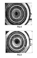
- FIG. 4 is a digital image of a valve structure as produced by an optoelectronic inspection system of the present disclosure, showing a dark ring resulting from use of diffuse light and a polished surface, indicating a satisfactory valve structure.
- FIG. 5 is a digital image of a valve structure generated by an optoelectronic inspection system of the present disclosure, which in contrast to the valve structure image of FIG. 4 shows a white ring indicative of an unsatisfactory valve structure.
- FIG. 6 is a digital image of a 0.500 inch newly manufactured valve structure generated by an optoelectronic inspection system of the present disclosure, in which pristine surface of the valve structure reflects light away from the optics and appears black, indicating acceptable valve structure.
- FIG. 7 is a digital image generated by an optoelectronic inspection system of the present disclosure, for a valve structure of a 0.500 inch valve after a period in service in which damaged sealing surface of the valve structure scatters light that is collected by the optics and appears brighter in relation to the digital image of FIG. 6 , indicating unacceptable valve structure that however is sufficiently re-workable as to be amenable to reconditioning thereof.
- FIG. 8 is a digital image generated by an optoelectronic inspection system of the present disclosure, for a valve structure of a 0.500 inch valve after a period in service in which a significantly damaged sealing surface of the valve structure scatters light that is collected by the optics and appears bright and shiny in relation to the digital images of FIG. 6 and FIG. 7 , indicating valve structure that is so extensive as to require scrapping of the valve, as not being amenable to reconditioning of the valve.
- FIG. 9 is a digital image of a 0.250 inch newly manufactured valve structure generated by an optoelectronic inspection system of the present disclosure, in which pristine surface of the valve structure reflects light away from the optics and appears black, indicating acceptable valve structure.
- FIG. 10 is a digital image generated by an optoelectronic inspection system of the present disclosure, for a valve structure of a 0.250 inch valve after a period in service in which damaged sealing surface of the valve structure scatters light that is collected by the optics and appears brighter in relation to the digital image of FIG. 6 , indicating unacceptable valve structure that however is sufficiently re-workable as to be amenable to reconditioning thereof.
- FIG. 11 is a digital image generated by an optoelectronic inspection system of the present disclosure, for a valve structure of a 0.500 inch valve after a period in service in which damaged sealing surface of the valve structure scatters light that is collected by the optics and identifies an unacceptable valve structure that however is sufficiently re-workable as to be amenable to reconditioning thereof
- FIG. 12 is a digital image generated by an optoelectronic inspection system of the present disclosure, for the valve structure of FIG. 11 after polishing thereof, showing a detected defect.
- FIG. 13 is a digital image generated by an optoelectronic inspection system of the present disclosure, for the valve structure of FIG. 12 after polishing and wiping thereof with a cellulosic wiping pad.
- FIG. 14 is a digital image generated by an optoelectronic inspection system of the present disclosure, for the valve structure of a flat valve whose sealing surface has been crushed by over tightening, resulting in a larger outer diameter and a smaller inner diameter, as shown in the enlarged view of FIG. 15 .
- FIG. 15 is a digital image generated by an optoelectronic inspection system of the present invention, for the valve structure of FIG. 14 .
- FIG. 16 is a digital image generated by an optoelectronic inspection system of the present disclosure, for a valve structure of an aged valve after extensive service, in which the sealing surface has moved inwardly as the valve has been worn and/or previously polished, as shown by the relative position of the registration elements of the optics system in relation to the sealing surface dark ring, as shown in enlarged scale in FIG. 17 .
- FIG. 17 is a digital image generated by an optoelectronic inspection system of the present invention, for the valve structure of FIG. 16 .
- the present disclosure relates to an optoelectronic inspection system useful for quality assurance determinations of fluid dispensing valves, e.g., as installed on fluid storage and dispensing vessels, as well as to associated methodology and non-transitory computable readable media storing machine-executable instructions for such quality assurance determinations.
- the disclosure relates to an optoelectronic inspection system for determining acceptability of a valve structure, comprising:
- an inspection station adapted to position the valve structure for optoelectronic imaging
- a light source arranged to impinge light on the valve structure
- a camera/lens assembly arranged to receive light resulting from interaction of the valve structure and light impinged on the valve structure from the light source, and to responsively generate an optoelectronic imaging output;
- a central processing unit arranged to receive the optoelectronic imaging output from the camera/lens assembly and to responsively generate an inspection output indicative of whether the valve structure satisfies predetermined acceptability criteria.
- the inspection station in one embodiment is adapted to position the valve structure for optoelectronic imaging, via a holder arranged to retain a fluid supply package including a valve head assembly comprising said valve structure in appropriate position for optoelectronic imaging.
- the light source in the optoelectronic inspection system can be of any suitable type, and may for example comprise an illumination device selected from the group consisting of incandescent lamps, light emitting diodes, lasers, ultraviolet lamps, and infrared lamps.
- the light source may therefore be of a type emitting visible light, infrared radiation, ultraviolet radiation, or other suitable light output that when impinged on the valve structure enables a response signature to be produced that is correlative of the character, quality or condition of the valve structure.
- the central processing unit in the optoelectronic inspection system can likewise be of any suitable type, and may for example comprise a processor generating a colorimetric inspection output indicative of whether the valve structure satisfies predetermined acceptability criteria.
- the colorimetric inspection output can be of any color or color combination that provides an appropriate inspection result.
- the colorimetric inspection output can comprise a green color output when a valve structure satisfies the predetermined acceptability criteria, and a red color output when a valve structure does not satisfy the predetermined acceptability criteria.
- the central processing unit of the optoelectronic inspection system may be of any appropriate type, and may for example comprise a non-transitory computer readable medium storing machine-executable instructions for determining acceptability of a valve structure.
- the central processing unit may comprise a non-transitory computer readable medium storing a database of criteria of acceptable valve structure.
- the central processing unit may be adapted to process the optoelectronic imaging output from the camera/lens assembly for determination of compatibility thereof with the criteria of acceptable valve structure in order to responsively generate the inspection output indicative of whether the valve structure satisfies the predetermined acceptability criteria.
- the optoelectronic inspection system further comprises a transporter apparatus adapted to move a fluid supply package including the valve structure being assessed, from the inspection station to one of multiple receiving areas dependent on extent of matching by a valve structure thereof to the predetermined acceptability criteria.
- the receiving areas may for example include a first area for receipt of fluid supply packages whose valve structure satisfies the predetermined acceptability criteria, and a second area for receipt of fluid supply packages whose valve structure does not satisfy the predetermined acceptability criteria.
- the receiving areas may include a third area for receipt of fluid supply packages whose valve structure does not satisfy the predetermined acceptability criteria, but is within a predetermined sufficient proximity to the predetermined acceptability criteria so as to be reworkable to yield a reworked valve structure satisfying the predetermined acceptability criteria.
- the disclosure in another aspect relates to a method for determining acceptability of a valve structure, comprising:
- valve structure can be a component of a valve head assembly of a fluid supply package.
- valve structure may be internal valve chamber structure of a flow control valve per se.
- the method may be carried out with any suitable light source, e.g., an illumination device selected from the group consisting of incandescent lamps, light emitting diodes, lasers, ultraviolet lamps, and infrared lamps.
- an illumination device selected from the group consisting of incandescent lamps, light emitting diodes, lasers, ultraviolet lamps, and infrared lamps.
- the light source utilized in the quality assurance determination of the present disclosure may emit visible light, infrared radiation, ultraviolet radiation, or any other suitable electromagnetic radiation.
- the method may be carried out to produce an inspection output comprising a colorimetric inspection output indicative of whether the valve structure satisfies predetermined acceptability criteria, e.g., a colorimetric inspection output comprising a green color output when a valve structure satisfies the predetermined acceptability criteria, and a red color output when a valve structure does not satisfy the predetermined acceptability criteria.
- a colorimetric inspection output indicative of whether the valve structure satisfies predetermined acceptability criteria
- predetermined acceptability criteria e.g., a colorimetric inspection output comprising a green color output when a valve structure satisfies the predetermined acceptability criteria, and a red color output when a valve structure does not satisfy the predetermined acceptability criteria.
- the method may be conducted with the central processing unit comprising a non-transitory computer readable medium that stores machine-executable instructions for determining the acceptability of a valve structure.
- the central processing unit may comprise a non-transitory computer readable medium storing a database of criteria of acceptable valve structure.
- the central processing unit may be adapted to process the optoelectronic imaging output for determination of compatibility thereof with the criteria of acceptable valve structure in order to responsively generate the inspection output indicative of whether the valve structure satisfies predetermined acceptability criteria.
- the method may further comprise, after generating the inspection output, mechanically moving a fluid supply package comprising the valve structure to one of multiple receiving areas dependent on extent of matching by a valve structure thereof to the predetermined acceptability criteria.
- the receiving areas may include a first area for receipt of fluid supply packages whose valve structure satisfies the predetermined acceptability criteria, and a second area for receipt of fluid supply packages whose valve structure does not satisfy the predetermined acceptability criteria, and optionally a third area for receipt of fluid supply packages whose valve structure does not satisfy the predetermined acceptability criteria, but is within a predetermined sufficient proximity to the predetermined acceptability criteria so as to be reworkable to yield a reworked valve structure satisfying the predetermined acceptability criteria.
- the disclosure relates to a non-transitory computer readable medium storing machine-executable instructions which when executed carry out a quality assurance determination of a fluid dispensing valve including valve structure on which light has been impinged to produce an imaging response optoelectronically converted to an optoelectronic imaging output, wherein the optoelectronic imaging output is processed to generate an inspection output indicative of whether the valve structure satisfies predetermined acceptability criteria.
- the non-transitory computer readable medium may be constituted so that the processing of the optoelectronic imaging output comprises correlation thereof with fluid dispensing valve baseline information for a valve of a type being subjected to the quality assurance determination, from a database of fluid dispensing valve baseline information for multiple valve types.
- FIG. 1 is a schematic representation of an optoelectronic inspection system 100 according to one embodiment of the present disclosure.
- the system includes an inspection assembly 102 , comprising housing 104 and display screen 114 , reposed on bench 106 to constitute an inspection station.
- the countertop of bench 106 has a cutout on a frontal portion thereof to accommodate positioning of the vessel of the fluid storage and dispensing package 112 so that the net and valve head assembly of the vessel extend upwardly above the surface of the countertop, with the vessel positioned on pedestal 110 mounted in the bracket 108 secured to the underside of the countertop.
- a fluid storage and dispensing package 116 awaiting quality assurance testing by the inspection assembly 102 .
- the inspection station shown in FIG. 1 involves manual placement of successive fluid storage and dispensing packages in the bracket 108 on pedestal 110 for quality assurance determination, followed by manual removal of the fluid package from the bracket to accommodate the next-successive fluid package to be subjected to the quality assurance operation.
- the inspection station may be constructed, arranged and adapted for automated delivery and positioning of successive fluid packages in the bracket for quality assurance determination, and subsequent automated removal of the inspected fluid package from the bracket of the inspection station, and transport to a specific area dependent on the outcome of the quality assurance operation.
- the optoelectronic inspection system may further comprise a delivery and transport system that furnishes a fluid package to the inspection station, subjects the valve assembly of such fluid package to quality assurance determination, and then transports fluid packages satisfying quality assurance criteria to a first retention area, and transports fluid packages failing quality assurance criteria to a second retention area. Fluid packages in the second retention area then may be reworked, such as by removing the valve head assembly from the vessel of such package and replacing it with a replacement valve head assembly, subsequent which the fluid package is again submitted to quality assurance determination.
- a delivery and transport system that furnishes a fluid package to the inspection station, subjects the valve assembly of such fluid package to quality assurance determination, and then transports fluid packages satisfying quality assurance criteria to a first retention area, and transports fluid packages failing quality assurance criteria to a second retention area. Fluid packages in the second retention area then may be reworked, such as by removing the valve head assembly from the vessel of such package and replacing it with a replacement valve head assembly, subsequent which the fluid package is again submitted to quality assurance determination.
- FIG. 2 is a close-up perspective view of the optoelectronic inspection system of FIG. 1 , showing the features thereof.
- the inspection assembly 102 comprises a housing 104 containing optical and electronic componentry, as hereinafter more fully described.
- the inspection assembly 102 includes a display 114 , which may for example comprise a liquid crystal display or other visual output screen for display of data and/or results of the quality assurance determination.
- a fluid package is shown in the bracket 108 , supported on pedestal 110 , with the valve head assembly 120 of the fluid package being positioned by such arrangement for quality assurance determination.
- FIG. 3 is a close-up perspective view, partially broken away, of the inspection tool of FIG. 1 , showing the details of the tool.
- the inspection assembly 102 in FIG. 3 illustrates the housing 104 partially broken away to show the optical and electronic components in the housing, with the fluid package 112 positioned for quality assurance determination.
- the components of the inspection assembly include a central processing unit 132 operatively linked with a power supply 138 , a light source 136 , and camera/lens assembly 134 , with the valve assembly of fluid package 112 being positioned for quality assurance determination by fixture 140 , so that the valve nozzle is aligned with the light source and camera/lens assembly.
- the light source 136 is adapted to provide a low angled diffuse light for impingement on the valve structure so that the camera/lens assembly 134 can record an image of the valve structure providing quality assurance differentiability of the valve structure in relation to one or more standard or baseline images, to determine whether the valve structure satisfies acceptance criteria or fails such criteria.
- standard or baseline images are stored in a database or other electronic storage medium in the central processing unit 132 , and images recorded by the camera/lens assembly under selected lighting conditions provided by the light source are transmitted from the camera to the central processing unit for image comparison with the standard or baseline images for the fluid packages and valve head assemblies being subjected to quality assurance determination.
- the light source may be of any suitable type, and may include an incandescent light source, an LED light source, an infrared radiation source, or other illumination device producing output that is impinged on the valve structure to produce an illuminated image detectable by the camera/lens assembly 134 .
- the camera/lens assembly is arranged to transmit the detected image to the central processing unit 132 for image processing in comparison against the standard or baseline images, to determine whether the valve structure being subjected to quality assurance determination satisfies or fails the acceptance criteria for the valve structure.
- the central processing unit 132 may be arranged to process the image signals from camera/lens assembly 134 in any appropriate manner.
- the image data from the valve structure may be constituted as an autocorrelation function that then is Fourier transformed to yield an illumination power spectrum for digital comparison to baseline or standard spectra for acceptable valve structure, so that the central processing unit outputs the quality assurance determination, e.g., as a visual output to the display screen 114 (see FIGS. 1 and 2 ).
- the visual output can for example comprise a colorimetric output, with a green color indication depicting satisfaction of the quality assurance criteria, a yellow color indication depicting borderline satisfaction of the quality assurance criteria, and a red color indication depicting failure of the quality assurance criteria.
- the central processing unit may comprise a processor to mitigating with a memory via an address/data bus, wherein the processor can include any commercially available or custom microprocessor, and wherein the memory contains the software instructions and data utilized to implement the functionality of the central processing unit.
- the memory can include, without limitation, cache, ROM, PROM, EPROM, EEPROM, flash memory, SRAM, and DRAM.
- the memory may include various categories of software and data used in the central processing unit, including the operating system, application programs, input/output device drivers, and data, e.g., including a database of acceptable valve structures, in the form of spectral data, image profiles, or other image data.
- the central processing unit comprises a non-transitory computer readable medium storing machine executable instructions, which when executed by a processor, perform a quality assurance determination for the valve structure being assessed in the quality assurance operation, e.g., to accept or reject the valve structure being assessed, in relation to a predetermined standard or other acceptance criteria.
- a quality assurance determination for the valve structure being assessed in the quality assurance operation, e.g., to accept or reject the valve structure being assessed, in relation to a predetermined standard or other acceptance criteria.
- criteria is intended to be broadly construed to encompass a single criterion, as well as multiple quality assurance conditions, values, or characteristics.
- FIG. 4 is a digital image of a valve structure as produced by an optoelectronic inspection system of the present disclosure, showing a dark ring resulting from use of diffuse light and a polished surface, indicating a satisfactory valve structure.
- FIG. 5 is a digital image of a valve structure generated by an optoelectronic inspection system of the present disclosure, which in contrast to the valve structure image of FIG. 4 shows a white ring indicative of an unsatisfactory valve structure.
- FIG. 6 is a digital image of a 0.500 inch newly manufactured valve structure generated by an optoelectronic inspection system of the present disclosure, in which pristine surface of the valve structure reflects light away from the optics and appears black, indicating acceptable valve structure.
- the image scanned by the lens/camera assembly is shown on the left-hand side of FIG. 6 , showing the individual scan segments, each of which is separately assessed for its character, quality, or condition, as shown by the individual rectangular scan elements superposed on the valve structure, and with the scanned image shown for comparison on the right-hand portion of FIG. 6 , without the superposed rectangular scan element array.
- FIG. 7 is a digital image generated by an optoelectronic inspection system of the present disclosure, for a valve structure of a 0.500 inch valve after a period in service in which damaged sealing surface of the valve structure scatters light that is collected by the optics and appears brighter in relation to the digital image of FIG. 6 , indicating unacceptable valve structure that however is sufficiently re-workable as to be amenable to reconditioning thereof.
- FIG. 8 is a digital image generated by an optoelectronic inspection system of the present disclosure, for a valve structure of a 0.500 inch valve after a period in service in which a significantly damaged sealing surface of the valve structure scatters light that is collected by the optics and appears bright and shiny in relation to the digital images of FIG. 6 and FIG. 7 , indicating valve structure that is so extensive as to require scrapping of the valve, as not being amenable to reconditioning of the valve.
- FIG. 9 is a digital image of a 0.250 inch newly manufactured valve structure generated by an optoelectronic inspection system of the present disclosure, in which pristine surface of the valve structure reflects light away from the optics and appears black, indicating acceptable valve structure.
- FIG. 10 is a digital image generated by an optoelectronic inspection system of the present disclosure, for a valve structure of a 0.250 inch valve after a period in service in which damaged sealing surface of the valve structure scatters light that is collected by the optics and appears brighter in relation to the digital image of FIG. 6 , indicating unacceptable valve structure that however is sufficiently re-workable as to be amenable to reconditioning thereof.
- FIG. 11 is a digital image generated by an optoelectronic inspection system of the present disclosure, for a valve structure of a 0.500 inch valve after a period in service in which damaged sealing surface of the valve structure scatters light that is collected by the optics and identifies an unacceptable valve structure that however is sufficiently re-workable as to be amenable to reconditioning thereof
- FIG. 12 is a digital image generated by an optoelectronic inspection system of the present disclosure, for the valve structure of FIG. 11 after polishing thereof, showing a detected defect.
- FIG. 13 is a digital image generated by an optoelectronic inspection system of the present disclosure, for the valve structure of FIG. 12 after polishing and wiping thereof with a cellulosic wiping pad.
- FIG. 14 is a digital image generated by an optoelectronic inspection system of the present disclosure, for the valve structure of a flat valve whose sealing surface has been crushed by over tightening, resulting in a larger outer diameter and a smaller inner diameter, as shown in the enlarged view of FIG. 15 .
- FIG. 16 is a digital image generated by an optoelectronic inspection system of the present disclosure, for a valve structure of an aged valve after extensive service, in which the sealing surface has moved inwardly as the valve has been worn and/or previously polished, as shown by the relative position of the registration elements of the optics system in relation to the sealing surface dark ring, as shown in enlarged scale in FIG. 17 .
- the optoelectronic inspection system of the present disclosure may be arranged to generate successive images of respective valve structures for pass/fail visual determination of acceptability by the central processing unit in relation to reflectance, scattering, brightness, darkness, and/or other optical characteristics yielded by impingement of the light from the light source on the valve structure undergoing assessment, with such characteristics being evaluated for a multiplicity of pixels or image regions by the central processing unit.
- the image processing algorithms embodied in the software of the central processing unit can be utilized to generate an output, based on average, mean or other representative value(s) in comparison to predetermined acceptance criteria, to provide an operator of the inspection system with a visual representation indicative of a pass/fail determination.
- the operator of the inspection station can then tag or otherwise identify the accepted or non-accepted status of the fluid supply package and place the fluid supply package in a specific location reflecting its accepted or non-accepted status.
- the workstation of the optoelectronic inspection system can be arranged to be fully automated so that respective fluid supply packages are advanced in sequence to the inspection station, placed in position for optical imaging of the valve structure, optically imaged and then automatically transported to an appropriate one of rejected, rework, or accepted package locations, depending on which of such status categories is applicable to a given individual fluid supply package.
- the optoelectronic inspection system of the present disclosure can be widely varied in componentry, layout and operation, to provide a ready and reproducible determination of whether a specific valve structure is acceptable for fluid storage and dispensing operation.
- the inspection system has been described in reference to inspection of valve structures of valves already mounted on vessels of the corresponding fluid supply package, it will be recognized that the valve structure may be inspected prior to securing the valve head assembly to the vessel of the corresponding fluid supply package.
Landscapes
- Physics & Mathematics (AREA)
- General Physics & Mathematics (AREA)
- General Health & Medical Sciences (AREA)
- Chemical & Material Sciences (AREA)
- Analytical Chemistry (AREA)
- Biochemistry (AREA)
- Life Sciences & Earth Sciences (AREA)
- Health & Medical Sciences (AREA)
- Immunology (AREA)
- Pathology (AREA)
- Investigating Materials By The Use Of Optical Means Adapted For Particular Applications (AREA)
- Indication Of The Valve Opening Or Closing Status (AREA)
- Investigating Or Analysing Materials By Optical Means (AREA)
Abstract
Description
Claims (20)
Priority Applications (1)
| Application Number | Priority Date | Filing Date | Title |
|---|---|---|---|
| US14/433,363 US9518933B2 (en) | 2012-10-13 | 2013-10-12 | Opto-electronic inspection quality assurance system for fluid dispensing valves |
Applications Claiming Priority (3)
| Application Number | Priority Date | Filing Date | Title |
|---|---|---|---|
| US201261713492P | 2012-10-13 | 2012-10-13 | |
| PCT/US2013/064732 WO2014059395A1 (en) | 2012-10-13 | 2013-10-12 | Opto-electronic inspection quality assurance system for fluid dispensing valves |
| US14/433,363 US9518933B2 (en) | 2012-10-13 | 2013-10-12 | Opto-electronic inspection quality assurance system for fluid dispensing valves |
Publications (2)
| Publication Number | Publication Date |
|---|---|
| US20150276619A1 US20150276619A1 (en) | 2015-10-01 |
| US9518933B2 true US9518933B2 (en) | 2016-12-13 |
Family
ID=50477971
Family Applications (1)
| Application Number | Title | Priority Date | Filing Date |
|---|---|---|---|
| US14/433,363 Expired - Fee Related US9518933B2 (en) | 2012-10-13 | 2013-10-12 | Opto-electronic inspection quality assurance system for fluid dispensing valves |
Country Status (5)
| Country | Link |
|---|---|
| US (1) | US9518933B2 (en) |
| KR (1) | KR20150070251A (en) |
| CN (1) | CN104870983B (en) |
| TW (1) | TWI622725B (en) |
| WO (1) | WO2014059395A1 (en) |
Families Citing this family (2)
| Publication number | Priority date | Publication date | Assignee | Title |
|---|---|---|---|---|
| US10180248B2 (en) | 2015-09-02 | 2019-01-15 | ProPhotonix Limited | LED lamp with sensing capabilities |
| US10880331B2 (en) * | 2019-11-15 | 2020-12-29 | Cheman Shaik | Defeating solution to phishing attacks through counter challenge authentication |
Citations (7)
| Publication number | Priority date | Publication date | Assignee | Title |
|---|---|---|---|---|
| US3680966A (en) * | 1971-03-12 | 1972-08-01 | Iris Corp | Apparatus and method for shell inspection |
| US4692943A (en) | 1983-12-30 | 1987-09-08 | Dr. Ludwig Pietzsch Gmbh | Method of and system for opto-electronic inspection of a two-dimensional pattern on an object |
| US5279729A (en) | 1989-03-20 | 1994-01-18 | Murata Kikai Kabushiki Kaisha | Bobbin sorting device |
| US5389544A (en) * | 1990-02-21 | 1995-02-14 | Mitsubishi Jukogyo Kabushiki Kaisha | Method for counting living cells of microbes and apparatus therefor |
| US5680473A (en) | 1989-12-19 | 1997-10-21 | Nippon Mining & Metals Co., Ltd. | Surface inspection device |
| US20040218807A1 (en) | 1990-11-16 | 2004-11-04 | Applied Materials, Inc. | Optical inspection method for substrate defect detection |
| US20080186481A1 (en) | 2007-02-06 | 2008-08-07 | Chien-Lung Chen | Optical vision inspection apparatus |
Family Cites Families (2)
| Publication number | Priority date | Publication date | Assignee | Title |
|---|---|---|---|---|
| CN2859539Y (en) * | 2005-12-14 | 2007-01-17 | 中国印钞造币总公司 | Surface quality on-line checkout device for coin completed product |
| CN101013079B (en) * | 2007-02-07 | 2010-11-10 | 浙江大学 | Small-sized material digitalized detecting and grading apparatus |
-
2013
- 2013-10-11 TW TW102136793A patent/TWI622725B/en not_active IP Right Cessation
- 2013-10-12 CN CN201380064238.4A patent/CN104870983B/en not_active Expired - Fee Related
- 2013-10-12 KR KR1020157012191A patent/KR20150070251A/en not_active Ceased
- 2013-10-12 WO PCT/US2013/064732 patent/WO2014059395A1/en active Application Filing
- 2013-10-12 US US14/433,363 patent/US9518933B2/en not_active Expired - Fee Related
Patent Citations (7)
| Publication number | Priority date | Publication date | Assignee | Title |
|---|---|---|---|---|
| US3680966A (en) * | 1971-03-12 | 1972-08-01 | Iris Corp | Apparatus and method for shell inspection |
| US4692943A (en) | 1983-12-30 | 1987-09-08 | Dr. Ludwig Pietzsch Gmbh | Method of and system for opto-electronic inspection of a two-dimensional pattern on an object |
| US5279729A (en) | 1989-03-20 | 1994-01-18 | Murata Kikai Kabushiki Kaisha | Bobbin sorting device |
| US5680473A (en) | 1989-12-19 | 1997-10-21 | Nippon Mining & Metals Co., Ltd. | Surface inspection device |
| US5389544A (en) * | 1990-02-21 | 1995-02-14 | Mitsubishi Jukogyo Kabushiki Kaisha | Method for counting living cells of microbes and apparatus therefor |
| US20040218807A1 (en) | 1990-11-16 | 2004-11-04 | Applied Materials, Inc. | Optical inspection method for substrate defect detection |
| US20080186481A1 (en) | 2007-02-06 | 2008-08-07 | Chien-Lung Chen | Optical vision inspection apparatus |
Also Published As
| Publication number | Publication date |
|---|---|
| WO2014059395A1 (en) | 2014-04-17 |
| US20150276619A1 (en) | 2015-10-01 |
| CN104870983B (en) | 2018-03-27 |
| CN104870983A (en) | 2015-08-26 |
| TW201422955A (en) | 2014-06-16 |
| KR20150070251A (en) | 2015-06-24 |
| TWI622725B (en) | 2018-05-01 |
Similar Documents
| Publication | Publication Date | Title |
|---|---|---|
| KR102178903B1 (en) | Visual inspection device and illumination condition setting method of visual inspection device | |
| EP2609418B1 (en) | Defect inspection and photoluminescence measurement system | |
| JP5419304B2 (en) | Light emitting element inspection apparatus and inspection method thereof | |
| JP5009663B2 (en) | Appearance inspection system | |
| EP1714141B1 (en) | Device and method for detecting contamination in a container | |
| US8532364B2 (en) | Apparatus and method for detecting defects in wafer manufacturing | |
| US20070007466A1 (en) | Differential wavelength photoluminescence for non-contact measuring of contaminants and defects located below the surface of a wafer or other workpiece | |
| US9013688B2 (en) | Method for optical inspection, detection and analysis of double sided wafer macro defects | |
| JP2015148447A (en) | Automatic visual inspection apparatus | |
| CN107923837A (en) | Systems and methods for inspecting containers using multiple radiation sources | |
| US11828713B1 (en) | Semiconductor inspection tool system and method for wafer edge inspection | |
| JP2008249568A (en) | Appearance inspection device | |
| TW201733335A (en) | Contact lens defect inspection using UV illumination | |
| JP5830229B2 (en) | Wafer defect inspection system | |
| US9518933B2 (en) | Opto-electronic inspection quality assurance system for fluid dispensing valves | |
| US20070115464A1 (en) | System and method for inspection of films | |
| US7142707B2 (en) | Automated inspection of packaging materials for package integrity | |
| JP2019203701A (en) | Inspection device of packed egg | |
| WO2024003903A1 (en) | A semiconductor inspection tool system and method for wafer edge inspection | |
| KR102273936B1 (en) | Pre-Delivery Inspection Apparatus | |
| WO2008085160A1 (en) | System and method for inspection of films | |
| JP4698140B2 (en) | System for identifying defects in composite structures |
Legal Events
| Date | Code | Title | Description |
|---|---|---|---|
| AS | Assignment |
Owner name: ENTEGRIS, INC., MASSACHUSETTS Free format text: ASSIGNMENT OF ASSIGNORS INTEREST;ASSIGNOR:ADVANCED TECHNOLOGY MATERIALS, INC.;REEL/FRAME:034894/0025 Effective date: 20150204 |
|
| AS | Assignment |
Owner name: ENTEGRIS, INC., MASSACHUSETTS Free format text: ASSIGNMENT OF ASSIGNORS INTEREST;ASSIGNORS:CHATTERTON, THOMAS B.;CHEON, SEBUM;REEL/FRAME:035365/0039 Effective date: 20150406 |
|
| STCF | Information on status: patent grant |
Free format text: PATENTED CASE |
|
| AS | Assignment |
Owner name: GOLDMAN SACHS BANK USA, AS COLLATERAL AGENT, NEW Y Free format text: SECURITY INTEREST;ASSIGNORS:ENTEGRIS, INC.;POCO GRAPHITE, INC.;REEL/FRAME:042375/0769 Effective date: 20170512 Owner name: GOLDMAN SACHS BANK USA, AS COLLATERAL AGENT, NEW Y Free format text: SECURITY INTEREST;ASSIGNORS:ENTEGRIS, INC.;POCO GRAPHITE, INC.;REEL/FRAME:042375/0740 Effective date: 20170512 Owner name: GOLDMAN SACHS BANK USA, AS COLLATERAL AGENT, NEW YORK Free format text: SECURITY INTEREST;ASSIGNORS:ENTEGRIS, INC.;POCO GRAPHITE, INC.;REEL/FRAME:042375/0769 Effective date: 20170512 Owner name: GOLDMAN SACHS BANK USA, AS COLLATERAL AGENT, NEW YORK Free format text: SECURITY INTEREST;ASSIGNORS:ENTEGRIS, INC.;POCO GRAPHITE, INC.;REEL/FRAME:042375/0740 Effective date: 20170512 |
|
| AS | Assignment |
Owner name: GOLDMAN SACHS BANK USA, NEW YORK Free format text: SECURITY INTEREST;ASSIGNORS:ENTEGRIS, INC.;SAES PURE GAS, INC.;REEL/FRAME:048811/0679 Effective date: 20181106 |
|
| AS | Assignment |
Owner name: MORGAN STANLEY SENIOR FUNDING, INC., MARYLAND Free format text: ASSIGNMENT OF PATENT SECURITY INTEREST RECORDED AT REEL/FRAME 048811/0679;ASSIGNOR:GOLDMAN SACHS BANK USA;REEL/FRAME:050965/0035 Effective date: 20191031 |
|
| FEPP | Fee payment procedure |
Free format text: MAINTENANCE FEE REMINDER MAILED (ORIGINAL EVENT CODE: REM.); ENTITY STATUS OF PATENT OWNER: LARGE ENTITY |
|
| LAPS | Lapse for failure to pay maintenance fees |
Free format text: PATENT EXPIRED FOR FAILURE TO PAY MAINTENANCE FEES (ORIGINAL EVENT CODE: EXP.); ENTITY STATUS OF PATENT OWNER: LARGE ENTITY |
|
| STCH | Information on status: patent discontinuation |
Free format text: PATENT EXPIRED DUE TO NONPAYMENT OF MAINTENANCE FEES UNDER 37 CFR 1.362 |
|
| FP | Lapsed due to failure to pay maintenance fee |
Effective date: 20201213 |