US9518480B2 - Exhaust heat recovery device - Google Patents
Exhaust heat recovery device Download PDFInfo
- Publication number
- US9518480B2 US9518480B2 US14/400,295 US201314400295A US9518480B2 US 9518480 B2 US9518480 B2 US 9518480B2 US 201314400295 A US201314400295 A US 201314400295A US 9518480 B2 US9518480 B2 US 9518480B2
- Authority
- US
- United States
- Prior art keywords
- rankine cycle
- control
- refrigerant
- valve
- determination value
- Prior art date
- Legal status (The legal status is an assumption and is not a legal conclusion. Google has not performed a legal analysis and makes no representation as to the accuracy of the status listed.)
- Active, expires
Links
Images

Classifications
-
- F—MECHANICAL ENGINEERING; LIGHTING; HEATING; WEAPONS; BLASTING
- F01—MACHINES OR ENGINES IN GENERAL; ENGINE PLANTS IN GENERAL; STEAM ENGINES
- F01K—STEAM ENGINE PLANTS; STEAM ACCUMULATORS; ENGINE PLANTS NOT OTHERWISE PROVIDED FOR; ENGINES USING SPECIAL WORKING FLUIDS OR CYCLES
- F01K13/00—General layout or general methods of operation of complete plants
- F01K13/02—Controlling, e.g. stopping or starting
-
- F—MECHANICAL ENGINEERING; LIGHTING; HEATING; WEAPONS; BLASTING
- F01—MACHINES OR ENGINES IN GENERAL; ENGINE PLANTS IN GENERAL; STEAM ENGINES
- F01K—STEAM ENGINE PLANTS; STEAM ACCUMULATORS; ENGINE PLANTS NOT OTHERWISE PROVIDED FOR; ENGINES USING SPECIAL WORKING FLUIDS OR CYCLES
- F01K23/00—Plants characterised by more than one engine delivering power external to the plant, the engines being driven by different fluids
- F01K23/02—Plants characterised by more than one engine delivering power external to the plant, the engines being driven by different fluids the engine cycles being thermally coupled
- F01K23/06—Plants characterised by more than one engine delivering power external to the plant, the engines being driven by different fluids the engine cycles being thermally coupled combustion heat from one cycle heating the fluid in another cycle
- F01K23/065—Plants characterised by more than one engine delivering power external to the plant, the engines being driven by different fluids the engine cycles being thermally coupled combustion heat from one cycle heating the fluid in another cycle the combustion taking place in an internal combustion piston engine, e.g. a diesel engine
-
- F—MECHANICAL ENGINEERING; LIGHTING; HEATING; WEAPONS; BLASTING
- F01—MACHINES OR ENGINES IN GENERAL; ENGINE PLANTS IN GENERAL; STEAM ENGINES
- F01K—STEAM ENGINE PLANTS; STEAM ACCUMULATORS; ENGINE PLANTS NOT OTHERWISE PROVIDED FOR; ENGINES USING SPECIAL WORKING FLUIDS OR CYCLES
- F01K23/00—Plants characterised by more than one engine delivering power external to the plant, the engines being driven by different fluids
- F01K23/02—Plants characterised by more than one engine delivering power external to the plant, the engines being driven by different fluids the engine cycles being thermally coupled
- F01K23/06—Plants characterised by more than one engine delivering power external to the plant, the engines being driven by different fluids the engine cycles being thermally coupled combustion heat from one cycle heating the fluid in another cycle
- F01K23/10—Plants characterised by more than one engine delivering power external to the plant, the engines being driven by different fluids the engine cycles being thermally coupled combustion heat from one cycle heating the fluid in another cycle with exhaust fluid of one cycle heating the fluid in another cycle
-
- F—MECHANICAL ENGINEERING; LIGHTING; HEATING; WEAPONS; BLASTING
- F01—MACHINES OR ENGINES IN GENERAL; ENGINE PLANTS IN GENERAL; STEAM ENGINES
- F01K—STEAM ENGINE PLANTS; STEAM ACCUMULATORS; ENGINE PLANTS NOT OTHERWISE PROVIDED FOR; ENGINES USING SPECIAL WORKING FLUIDS OR CYCLES
- F01K27/00—Plants for converting heat or fluid energy into mechanical energy, not otherwise provided for
- F01K27/02—Plants modified to use their waste heat, other than that of exhaust, e.g. engine-friction heat
-
- F—MECHANICAL ENGINEERING; LIGHTING; HEATING; WEAPONS; BLASTING
- F01—MACHINES OR ENGINES IN GENERAL; ENGINE PLANTS IN GENERAL; STEAM ENGINES
- F01K—STEAM ENGINE PLANTS; STEAM ACCUMULATORS; ENGINE PLANTS NOT OTHERWISE PROVIDED FOR; ENGINES USING SPECIAL WORKING FLUIDS OR CYCLES
- F01K7/00—Steam engine plants characterised by the use of specific types of engine; Plants or engines characterised by their use of special steam systems, cycles or processes; Control means specially adapted for such systems, cycles or processes; Use of withdrawn or exhaust steam for feed-water heating
- F01K7/16—Steam engine plants characterised by the use of specific types of engine; Plants or engines characterised by their use of special steam systems, cycles or processes; Control means specially adapted for such systems, cycles or processes; Use of withdrawn or exhaust steam for feed-water heating the engines being only of turbine type
- F01K7/30—Steam engine plants characterised by the use of specific types of engine; Plants or engines characterised by their use of special steam systems, cycles or processes; Control means specially adapted for such systems, cycles or processes; Use of withdrawn or exhaust steam for feed-water heating the engines being only of turbine type the turbines using exhaust steam only
-
- F—MECHANICAL ENGINEERING; LIGHTING; HEATING; WEAPONS; BLASTING
- F02—COMBUSTION ENGINES; HOT-GAS OR COMBUSTION-PRODUCT ENGINE PLANTS
- F02G—HOT GAS OR COMBUSTION-PRODUCT POSITIVE-DISPLACEMENT ENGINE PLANTS; USE OF WASTE HEAT OF COMBUSTION ENGINES; NOT OTHERWISE PROVIDED FOR
- F02G5/00—Profiting from waste heat of combustion engines, not otherwise provided for
-
- F—MECHANICAL ENGINEERING; LIGHTING; HEATING; WEAPONS; BLASTING
- F02—COMBUSTION ENGINES; HOT-GAS OR COMBUSTION-PRODUCT ENGINE PLANTS
- F02G—HOT GAS OR COMBUSTION-PRODUCT POSITIVE-DISPLACEMENT ENGINE PLANTS; USE OF WASTE HEAT OF COMBUSTION ENGINES; NOT OTHERWISE PROVIDED FOR
- F02G2260/00—Recuperating heat from exhaust gases of combustion engines and heat from cooling circuits
-
- Y—GENERAL TAGGING OF NEW TECHNOLOGICAL DEVELOPMENTS; GENERAL TAGGING OF CROSS-SECTIONAL TECHNOLOGIES SPANNING OVER SEVERAL SECTIONS OF THE IPC; TECHNICAL SUBJECTS COVERED BY FORMER USPC CROSS-REFERENCE ART COLLECTIONS [XRACs] AND DIGESTS
- Y02—TECHNOLOGIES OR APPLICATIONS FOR MITIGATION OR ADAPTATION AGAINST CLIMATE CHANGE
- Y02T—CLIMATE CHANGE MITIGATION TECHNOLOGIES RELATED TO TRANSPORTATION
- Y02T10/00—Road transport of goods or passengers
- Y02T10/10—Internal combustion engine [ICE] based vehicles
- Y02T10/12—Improving ICE efficiencies
-
- Y02T10/166—
Definitions
- the present invention relates to an exhaust heat recovery device provided with a Rankine cycle that recovers exhaust heat of an external heat source such as an engine and regenerates the exhaust heat as power.
- a waste-heat reusing device disclosed in Patent Document 1 has been known.
- the waste-heat reusing device disclosed in Patent Document 1 has: a Rankine cycle which is equipped with a pump, a heater, an expander, and a condenser; a bypass flow passage which bypasses the expander; and a bypass valve that opens and closes the bypass flow passage.
- refrigerant is first circulated with the bypass valve open, and when a temperature of gaseous-phase refrigerant on the inlet side of the expander becomes a predetermined temperature or higher, the bypass valve is closed, and operating rotational speeds of the expander and the pump are made to increase.
- the pressure difference ander pressure difference
- Patent Document 1 Japanese Patent Application Laid-open Publication No. 2009-97387
- the time required up to the start-up completion of the Rankine cycle that is, the time until the expander pressure difference becomes a predetermined pressure difference after closing the bypass valve has not been considered at all.
- the expander pressure difference when it does not become the predetermined pressure difference even if a certain amount of time has passed, it may also be considered not to actuate the Rankine cycle, but such a case is undesirable because there is a risk of a decrease in opportunities for actuating the Rankine cycle.
- the present invention has been made in view of such points, and an object thereof is to provide an exhaust heat recovery device provided with a Rankine cycle, capable of preventing the opportunities for actuating the Rankine cycle from being decreased and capable of efficiently operating the Rankine cycle.
- An exhaust heat recovery device includes: a Rankine cycle in which a heater configured to heat and vaporize refrigerant by exhaust heat of an external heat source, an expander configured to generate power by expanding the refrigerant passed through the heater, a condenser configured to condense the refrigerant passed through the expander, and a pump configured to send the refrigerant passed through the condenser to the heater are disposed in a circulation passage of the refrigerant; a bypass flow passage that allows the refrigerant to circulate while bypassing the expander; a bypass valve that opens and closes the bypass flow passage; a pressure difference determining unit that determines a pressure difference between a high-pressure side and a low-pressure side of the Rankine cycle; and a control unit that executes start-up control of the Rankine cycle, the start-up control actuating the pump with the bypass valve open and then closing the bypass valve, the control unit repeatedly executing the start-up control when the pressure difference after closing the bypass valve
- An exhaust heat recovery device includes: a Rankine cycle in which a heater configured to heat and vaporize refrigerant by exhaust heat of an external heat source, an expander configured to generate power by expanding the refrigerant passed through the heater, a condenser configured to condense the refrigerant passed through the expander, and a pump configured to send the refrigerant passed through the condenser to the heater are disposed in a circulation passage of the refrigerant; a bypass flow passage that allows the refrigerant to circulate while bypassing the expander; a bypass valve that opens and closes the bypass flow passage; a pressure difference determining unit that determines a pressure difference between a high-pressure side and a low-pressure side of the Rankine cycle; and a control unit that, when starting up the Rankine cycle, executes control to actuate the pump with the bypass valve open, and then to close the bypass valve when the pressure difference becomes a predetermined value, the control unit executing control to open the bypass valve when
- the exhaust heat recovery device when starting up the Rankine cycle, when the pressure difference between the high-pressure side and the low-pressure side of the Rankine cycle does not reach the start-up completion determination value within the predetermined time after the refrigerant is made to circulate via the expander by closing the bypass valve from the state in which the refrigerant circulates while bypassing the expander, the bypass valve is opened, and then, after making the refrigerant circulate while bypassing the expander, the bypass valve is closed again.
- the refrigerant can be circulated via the expander while the time in which the Rankine cycle is actuated with low efficiency can be prevent from being extended, and while the possibility that the Rankine cycle reaches the start-up completion is increased.
- the opportunities for actuating the Rankine cycle can be prevented from being decreased, and the Rankine cycle can be efficiently operated.
- FIG. 1 is a diagram illustrating a schematic configuration of an exhaust heat recovery device according to an embodiment of the present invention.
- FIG. 2 is a flowchart illustrating Rankine start-up control in the embodiment.
- FIG. 3 is a flowchart illustrating the Rankine start-up control in the embodiment.
- FIG. 4 is a timing diagram of the Rankine start-up control.
- FIG. 5 is a diagram illustrating an update (increase correction) of a valve-closing determination value ⁇ Ps 1 .
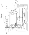
- FIG. 6 is a diagram illustrating a schematic configuration of an exhaust heat recovery device according to a modified example of the embodiment.
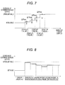
- FIG. 7 is a diagram illustrating another example of an update (increase correction) of a valve-closing determination value ⁇ Ps 1 .
- FIG. 8 is a diagram illustrating an example of a valve-closing determination value ⁇ Ps 1 that is corrected for each start-up of the Rankine cycle.
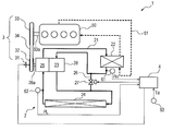
- FIG. 1 illustrates a schematic configuration of an exhaust heat recovery device 1 according to an embodiment of the present invention.
- the exhaust heat recovery device 1 is mounted on a vehicle, and recovers and uses exhaust heat of an engine 50 of the vehicle.
- the exhaust heat recovery device 1 includes: a Rankine cycle 2 that recovers the exhaust heat of the engine 50 and converts the exhaust heat into power; a transmission mechanism 3 that performs power transmission between the Rankine cycle 2 and the engine 50 ; and a control unit 4 that controls the overall operation of the exhaust heat recovery device 1 .
- the engine 50 is a water-cooled internal combustion engine and is cooled by engine cooling water that circulates in a cooling water flow passage 51 .
- a heater 22 of the Rankine cycle 2 to be described later is arranged on the cooling water flow passage 51 , so that the engine cooling water that has absorbed heat from the engine 50 flows through the heater 22 .
- the Rankine cycle 2 recovers the exhaust heat (heat of the engine cooling water in this case) of the engine 50 as an external heat source, converts it into power, and outputs the power.
- a refrigerant circulation passage 21 of the Rankine cycle 2 there are arranged the heater 22 , an expander 23 , a condenser 24 , and a pump 25 , in this order. Furthermore, between the heater 22 and the condenser 24 , a bypass passage 26 through which refrigerant flows to bypass the expander 23 is provided, and a bypass valve 27 that opens and closes the bypass passage 26 is provided in the bypass passage 26 . Operation of the bypass valve 27 is controlled by the control unit 4 .
- the heater 22 is a heat exchanger which heats the refrigerant to obtain superheated vapor, by performing heat exchange between the engine cooling water that has absorbed heat from the engine 50 and the refrigerant.
- the heater 22 may be configured to perform heat exchange between the refrigerant and the exhaust gas of the engine 10 , instead of the engine cooling water.
- the expander 23 is, for example, a scroll-type expander, and generates power (driving force) by expanding the refrigerant, which is the superheated vapor heated by the heater 22 , and by converting it into rotational energy.
- the condenser 24 is a heat exchanger which cools and condenses (liquefies) the refrigerant, by performing heat exchange between the refrigerant passed through the expander 23 and the ambient air.
- the pump 25 is a mechanical pump that sends the refrigerant (liquid refrigerant) liquefied by the condenser 24 to the heater 22 .
- the refrigerant which has been liquefied by the condenser 24 , is sent to the heater 22 by the pump 25 , the refrigerant circulates through each of the elements of the Rankine cycle 2 .
- the expander 23 and the pump 25 are integrally connected and configured as a “pump-integrated expander 28 ” having a common rotating shaft 28 a . That is, the rotating shaft 28 a of the pump-integrated expander 28 has a function as an output shaft of the expander 23 and a function as a drive shaft of the pump 25 .
- the transmission mechanism 3 has a pulley 32 that is attached to the rotating shaft 28 a of the pump-integrated expander 28 via an electromagnetic clutch 31 , a crank pulley 33 that is attached to a crankshaft 50 a of the engine 50 , and a belt 34 that is wrapped around the pulley 32 and the crank pulley 33 .
- the electromagnetic clutch 31 is controlled to be turned on (engaged) and turned off (disengaged) by the control unit 4 , so that the transmission mechanism 3 transfers and cuts off power between the engine 50 and the Rankine cycle 2 (more specifically, the pump-integrated expander 28 ).
- Measurement signals of various sensors are input to the control unit 4 .
- the control unit 4 executes start-up control of the Rankine cycle 2 (hereinafter, simply referred to as “Rankine start-up control”) to be described later.
- the high-pressure side pressure PH of the Rankine cycle 2 refers to a pressure in the refrigerant circulation passage 21 in a section extending from (the outlet of) the pump 25 to (the inlet of) the expander 23 through the heater 22
- the low-pressure side pressure PL of the Rankine cycle 2 refers to a pressure in the refrigerant circulation passage 21 in a section extending from (the outlet of) the expander 23 to (the inlet of) the pump 25 through the condenser 24 .
- the first pressure sensor 61 measures the pressure on the inlet side of the expander 23 (the outlet side of the heater 22 ) as the high-pressure side pressure PH of the Rankine cycle 2
- the second pressure sensor 62 measures the pressure on the inlet side of the pump 25 (the outlet side of the condenser 24 ) as the low-pressure side pressure PL of the Rankine cycle 2 .
- the pump 25 is a liquid feeding pump, and it is assumed that the refrigerant on the inlet side of the pump 25 is in a liquid-phase state (liquid refrigerant). However, when the pump 25 is installed at a position higher than a refrigerant liquid level in a receiver tank (not illustrated), for example, due to a limitation on a layout, the refrigerant on the inlet side of the pump 25 may become a gaseous-phase state (gaseous refrigerant) during stop of the Rankine cycle 2 .
- the pump is actuated in a state in which the gaseous refrigerant is mixed on the inlet side of the pump 25 in this manner, a sufficient amount of circulating refrigerant cannot be obtained, and accordingly, it takes a long time to start up the Rankine cycle 2 , or there might be a risk of failure in start-up of the Rankine cycle 2 . For this reason, when starting up the Rankine cycle 2 , it is necessary that the refrigerant of the inlet side of the pump be liquid refrigerant as much as possible.
- the inventors have confirmed that, in a case in which the refrigerant is circulated with the bypass valve 27 open, and the bypass valve 27 is closed after the refrigerant on the inlet side of the pump 25 is sufficiently liquefied, more specifically, after the refrigerant on the inlet side of the pump 25 becomes approximately 100% of liquid refrigerant, the reliability of the start-up of the Rankine cycle 2 can be improved.
- the start-up performance (rapidity and reliability of start-up) of the Rankine cycle 2 can be improved and the Rankine cycle 2 can be efficiently operated with the operating time, in which output of the Rankine cycle 2 is negative, reduced to a minimum required time.
- control unit 4 executes control to actuate the pump 25 with the bypass valve 27 open at first, and executes control to close the bypass valve 27 when a parameter indicating the condensation capacity of the condenser 24 becomes a predetermined value or more, that is, the control unit 4 executes Rankine start-up control, in which a valve-closing condition of the bypass valve 27 is that the parameter indicating the condensation capacity in the condenser 24 is a predetermined value or more.
- a pressure difference ⁇ P between the high-pressure side pressure PH and the low-pressure side pressure PL of the Rankine cycle 2 is used as a parameter indicating the condensation capacity of the condenser 24 .
- the reasons are as follows.
- the refrigerant flow rate is a value indicating magnitude of the condensation capacity.
- the refrigerant flow rate is correlated with the pressure loss of the refrigerant circuit (as the refrigerant flow rate increases, the pressure loss of the refrigerant circuit also increases).
- the pressure difference ⁇ P between the high-pressure side and the low-pressure side is equal to the pressure loss of the refrigerant circuit, and accordingly, the pressure difference is a value having a correlation with the refrigerant flow rate. Therefore, by determining the pressure difference ⁇ P, it is possible to easily determine (detect) the condensation capacity of the condenser 24 , more specifically, whether the refrigerant on the inlet side of the pump 25 becomes substantially 100% of liquid refrigerant, and the use of the pressure difference ⁇ P, which has less hunting or the like, can achieve a stable control.
- determining the pressure difference ⁇ P it is also possible to determine, after closing the bypass valve 27 , whether the expander 23 is in a state capable of generating power (driving force), that is, whether the start-up of the Rankine cycle 2 is completed.
- FIGS. 2 and 3 are flowcharts of the Rankine start-up control.
- control in these flowcharts is initiated, for example, upon receiving the operation request or the operation permission of the Rankine cycle 2 .
- step S 1 it is determined whether “start-up failure” has been determined (see step S 15 to be described later).
- the process proceeds to step S 2 , and when the “start-up failure” has been determined, that is, in the redone Rankine start-up control, the process proceeds to step S 3 .
- an initial value of a valve-closing determination value (pressure) ⁇ Ps 1 for determining whether the bypass valve 27 is closed is set.
- a reference value for example, any value between 0.1 to 0.25 MPa
- a sufficient amount of liquid refrigerant substantially 100%
- valve-closing determination value ⁇ Ps 1 when the start-up completion was determined after the valve-closing determination value ⁇ Ps 1 was updated in the previous Rankine start-up control, the stored valve-closing determination value ⁇ Ps 1 after the update is set as the initial value (see step S 17 which will be described later).
- the valve-closing determination value ⁇ Ps 1 is updated (increase correction). Specifically, the valve-closing determination value ⁇ Ps 1 is updated by adding a correction value ⁇ Phos to the valve-closing determination value ⁇ Ps 1 , which is a currently determined (set) value ( ⁇ Ps 1 ⁇ Ps 1 + ⁇ Phos).
- the correction value ⁇ Phos may be, for example, 0.02 MPa.
- valve-closing determination value ⁇ Ps 1 has an upper limit value
- the valve-closing determination value ⁇ Ps 1 updated (increase correction) at step S 3 is limited to the upper limit value or less.
- the upper limit value used herein may be any value between 0.25 to 0.4 MPa.
- step S 4 the valve-closing determination value ⁇ Ps 1 to be used at step S 10 which will be described later is determined.
- the initial value set at step S 2 (that is, the reference value of the valve-closing determination value ⁇ Ps 1 or the valve-closing determination value ⁇ Ps 1 after update, which was updated and stored in the previous Rankine start-up control) is set as the valve-closing determination value ⁇ Ps 1 to be used at step S 9 , as it is.
- the valve-closing determination value ⁇ Ps 1 updated (corrected) at step S 3 is set as the valve-closing determination value ⁇ Ps 1 to be used at step S 10 . Therefore, the valve-closing determination value ⁇ Ps 1 to be used at step S 10 increases by the correction value ⁇ Phos each time the “start-up failure” is determined at step S 15 , but the valve-closing determination value ⁇ Ps 1 after correction (update) is limited to the upper limit value or less.
- step S 5 it is determined whether the bypass valve 27 is open.
- the process proceeds to step S 6 , and when the bypass valve 27 is open, the process proceeds to step S 7 .
- step S 6 the bypass valve 27 is opened.
- the bypass valve 27 is open typically. For this reason, in the first Rankine start-up control, the process of the above-described step S 6 may be typically omitted. Meanwhile, in the redone Rankine start-up control after a start-up failure (see step S 15 which will be described below), since the bypass valve 27 is closed (see step S 12 which will be described below), the bypass valve 27 is opened at the above-described step S 6 .
- step S 7 it is determined whether the electromagnetic clutch 31 is turned on (engaged).
- the process proceeds to step S 8 , and when the electromagnetic clutch 31 is already turned on, that is, when the Rankine start-up control is redone, the process proceeds to step S 9 .
- step S 8 the electromagnetic clutch 31 is turned on (engaged).
- the electromagnetic clutch 31 is turned on, the rotating shaft 28 a is driven to rotate by the engine 50 , and the pump 25 is actuated.
- the refrigerant circulates while bypassing the expander 23 .
- step S 9 it is determined whether a first predetermined time has elapsed from the beginning of the circulation of the refrigerant with the expander 23 bypassed. That is, in the first Rankine start-up control is executed, it is determined whether the first predetermined time has elapsed after turning on the electromagnetic clutch 31 at step S 8 , and in redoing of the Rankine start-up control, it is determined whether the first predetermined time has elapsed after opening the bypass valve 27 at step S 6 .
- the process proceeds to step S 10 .
- step S 11 the “poor pressure” is determined, and then, the process proceeds to step S 12 .
- the first predetermined time is set in advance to a period of time enough to sufficiently liquefy the refrigerant on the inlet side of the pump 25 (enough to be substantially 100% of liquid refrigerant) by actuating the pump 25 with the bypass valve 27 open, and the first predetermined time may be, for example, 120 seconds.
- step S 10 it is determined whether the pressure difference ⁇ P between the high-pressure side pressure PH and the low-pressure side pressure PL of the Rankine cycle 2 is equal to or greater than the valve-closing predetermined value ⁇ Ps 1 determined (set) at step S 4 .
- the process returns to step S 9 , and when the pressure difference ⁇ P is equal to or greater than the predetermined value ⁇ Ps 1 , the process proceeds to step S 12 .
- step S 12 the bypass valve 27 is closed.
- the refrigerant circulates via the expander 23 .
- the process proceeds to step S 13 .
- the bypass valve 27 is closed and the refrigerant is made to circulate via the expander 23 ; however, the electromagnetic clutch 31 may be turned off (disengaged) to terminate the Rankine start-up control.
- the initial value of the valve-closing determination value ⁇ Ps 1 set at the above-described step S 2 may be corrected based on a temperature Ta of ambient air.
- the initial value of the valve-closing determination value ⁇ Ps 1 is corrected to a greater value as the temperature Ta of ambient air decreases.
- the radiation performance of the condenser 24 increases, and the condensation temperature and the refrigerant temperature at the inlet of the pump 25 decreases.
- the refrigerant temperature at the inlet of the heater 22 on the high-pressure side also decreases, and the amount of liquid-phase refrigerant increases inside the heater 22 . Therefore, the amount of refrigerant on the low-pressure side decreases, and the degree of supercooling at the inlet of the pump 25 also decreases.
- an operation state becomes a state in which the degree of supercooling at the inlet of the pump 25 is hard to increase.
- the inlet of the pump 25 becomes a condition in which the refrigerant is hard to be liquefied. Therefore, in a case in which the temperature Ta of ambient air is low, when it is determined whether to close the bypass valve 27 using the same determination reference value, there is a possibility that the refrigerant at the inlet of the pump 25 is not sufficiently liquefied and a condition unfavorable to the start-up of the Rankine cycle 2 may occur.
- the control unit 4 corrects the initial value of the valve-closing determination value ⁇ Ps 1 to a greater value as the temperature Ta of ambient air decreases.
- the initial value of the valve-closing determination value ⁇ Ps 1 is about 0.15 MPa when the temperature Ta of ambient air is 25° C.
- the initial value of the valve-closing determination value ⁇ Ps 1 can be set to about 0.2 MPa when the temperature Ta of ambient air is about 5° C.
- the control unit 4 may be input with a vehicle speed, for example, from an engine control unit (not illustrated) and the initial value of the valve-closing determination value ⁇ Ps 1 may be corrected based on the input vehicle speed. In this case, the initial value of the valve-closing determination value ⁇ Ps 1 is corrected to a greater value as the vehicle speed increases. It should be apparent that the control unit 4 may correct (set) the initial value of the valve-closing determination value ⁇ Ps 1 based on both the temperature Ta of ambient air and the vehicle speed.
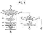
- step S 13 it is determined whether a second predetermined time ( ⁇ the first predetermined time) has elapsed after closing the bypass valve 27 at step S 12 .
- a second predetermined time ⁇ the first predetermined time
- the process proceeds to step S 14 .
- the process proceeds to step S 15 and the “start-up failure” is determined, and then, the process proceeds to step S 18 .
- the second predetermined time used here is set in advance to a period of time in which, in the normal operation (actuation) of the Rankine cycle 2 , the pressure difference ⁇ P can reach a start-up completion determination value ⁇ Ps 2 for determining the completion of the start-up of the Rankine cycle 2 (see step S 14 which will be described below), and may be, for example, 30 seconds.
- step S 14 it is determined whether the pressure difference ⁇ P between the high-pressure side pressure PH and the low-pressure side pressure PL of the Rankine cycle 2 is equal to greater than the start-up completion determination value ⁇ Ps 2 (>valve-closing determination value ⁇ Ps 1 ).
- the start-up completion determination value ⁇ Ps 2 is set depending on the Rankine cycle 2 , and may be, for example, 0.8 MPa.
- the process returns to step S 13 .
- step S 14 when the pressure difference ⁇ P is equal to or greater than the start-up completion determination value ⁇ Ps 2 , the process proceeds to step S 16 and the “start-up completion” is determined, the currently set (determined) valve-closing determination value ⁇ Ps 1 is stored at step S 17 , and the flow (that is, the Rankin start-up control) is terminated.
- the valve-closing determination value ⁇ Ps 1 stored at step S 17 is set as an initial value of the valve-closing determination value ⁇ Ps 1 in the next Rankine start-up control (see the above-described step S 2 ).
- the valve-closing determination value ⁇ Ps 1 stored at step S 17 becomes a value that is obtained by subtracting the correction amount due to the temperature Ta of ambient air and/or the correction amount due to the vehicle speed.
- the expander 23 is adapted to drive the pump 25 by generating the driving force, and when the driving force of the expander 23 exceeds the drive load of the pump 25 , the surplus driving force is supplied to the engine 50 via the transmission mechanism 3 to assist the engine output.
- step S 18 it is determined whether the “start-up failure” determination continues for a predetermined number of times (for example three times to five times).
- the process proceeds to step S 19 and the “start-up impossibility” is determined, and thereafter, the bypass valve 27 is opened at step S 20 , and the electromagnetic clutch 31 is turned off (disengaged) at step S 21 , to terminate the flow (Rankine start-up control). In this case, the actuation (operation) of the Rankine cycle 2 is not performed.
- the “start-up impossibility” since it is assumed that there are some kinds of abnormality in the Rankine cycle 2 , such as a shortage of the amount of refrigerant, it is preferable to notify the occupant or the like of the vehicle that there is abnormality in the Rankine cycle 2 by a warning light, a display, or the like.
- step S 22 determines whether the “poor pressure” (see step S 11 ) has been determined.
- step S 1 the process returns to step S 1 , to redo (repeat) the Rankine start-up control.
- the valve-closing determination value ⁇ Ps 1 is updated at step S 3 (increase correction).
- the “poor pressure” determination is reset (cancelled) at step S 23 , and then, the process returns to step S 5 , to redo (repeat) the Rankine start-up control.
- redoing of the Rankine start-up control in this case, unlike redoing of the Rankine start-up control when the “pressure failure” has not been determined, updating of the valve-closing determination value ⁇ Ps 1 (increase correction) is not performed.
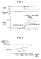
- FIG. 4 is a timing diagram of the Rankine start-up control.
- the electromagnetic clutch 31 When starting up the Rankine cycle 2 , the electromagnetic clutch 31 is turned on with the bypass valve 27 open (time t 0 ). As described above, since the bypass valve 27 is open during stop of the Rankine cycle 2 in this embodiment, the electromagnetic clutch 31 is only normally turned on. However, when the bypass valve 27 is closed during stop of the Rankine cycle 2 , the bypass valve 27 is opened and the electromagnetic clutch 31 is turned on. As a result, the pump 25 is activated, and the refrigerant circulates while bypassing the expander 23 .
- the “start-up failure” is determined and the bypass valve 27 is opened, to circulate the refrigerant again while bypassing the expander 23 . That is, the Rankine start-up control is redone.
- the “poor pressure” is determined. Also in this case, if the “start-up failure” is determined thereafter, the Rankine start-up control is redone. However, in redoing of the Rankine start-up control when the “poor pressure” has been determined, unlike redoing of the Rankine start-up control when the “pressure failure” has not been determined, an increase correction of the valve-closing determination value ⁇ Ps 1 is not performed.
- the bypass valve 27 can be closed after the refrigerant on the inlet side of the pump 25 is further liquefied (becoming liquid refrigerant) compared to the last Rankine start-up control. This makes it possible to further increase the possibility that the Rankine cycle 2 reaches the start-up completion.
- the valve-closing determination value ⁇ Ps 1 which has been subjected to the increase correction, is stored and is set as an initial value of the valve-closing determination value ⁇ Ps 1 in Rankine start-up control at the time of the next start-up of the Rankine cycle 2 .
- the pressure difference ⁇ P between the high-pressure side pressure PH and the low-pressure side pressure PL of the Rankine cycle 2 is used as a parameter indicating the condensation capacity of the condenser 24 .
- the invention is not limited to this, and in addition to or instead of the pressure difference ⁇ P, the degree of supercooling (subcooling) of the refrigerant on the outlet side of the condenser 24 (the inlet side of pump 25 ) may be used.
- the valve-closing condition of the bypass valve 27 is that the degree of supercooling (subcooling) of the refrigerant on the outlet side of the condenser 24 (the inlet side of the pump 25 ) is a predetermined value or more.
- a temperature sensor and a pressure sensor are installed between (the outlet of) the condenser 24 and (the inlet of) the pump 25 , and the control unit 4 calculates (determines) the degree of supercooling of the refrigerant, based on the temperature measured by the temperature sensor and the pressure measured by the pressure sensor 52 .
- the control unit 4 executes the control to actuate the pump 25 with the bypass valve 27 open, and to close the bypass valve 27 when the degree of supercooling of the refrigerant on the outlet side of the condenser 24 becomes a predetermined value or more.
- the predetermined value may be, for example, a value (refrigerant temperature) in which the refrigerant on the outlet side of the condenser 24 can be sufficiently liquefied.
- the increase correction is performed each time the “start-up failure” is determined. Also in this case, it is possible to obtain the same effects as that of the above-described embodiment.
- the flow rate of the liquid refrigerant sent from the pump 25 may be used as a parameter indicating the condensation capacity of the condenser 24 .
- the reason is that, as the condensation capacity of the condenser 24 increases, the flow rate of the liquid refrigerant sent from the pump 25 also increases.
- the valve-closing condition of the bypass valve 27 is that the flow rate of the liquid refrigerant sent from the pump 25 is a predetermined value or more.
- a flow sensor that measures the flow rate of liquid refrigerant is provided on the outlet side of the pump 25 .
- the control unit 4 executes the control to actuate the pump 25 with the bypass valve 27 open, and to close the bypass valve 27 when the flow rate of the liquid refrigerant sent from the pump 25 becomes a predetermined value or more.
- the predetermined value in this case may be set, for example, to the flow rate sent from the pump 25 when the refrigerant on the inlet side of the pump 25 is sufficiently liquefied, and the increase correction is performed each time “star-up failure” is determined. Also in this case, it is possible to obtain the same effects as that of the above-described embodiment.
- a pressure difference between the inlet side and the outlet side of the condenser 24 may be used as a parameter indicating the condensation capacity of the condenser 24 .
- the valve-closing condition of the bypass valve 27 is that the pressure difference between the inlet side and the outlet side of the condenser 24 is a predetermined value or more.
- a pressure sensor is provided on each of the inlet side and the outlet side of the condenser 24 , and the control unit 4 calculates (determines) the pressure difference between the inlet side and the outlet side of the condenser 24 .
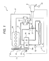
- the expander 23 and the pump 25 are formed as the “pump-integrated expander 28 ” connected by the same rotating shaft 28 a , but as illustrated in FIG. 6 , the expander 23 and the pump 25 may be separately formed.
- the exhaust heat recovery device 10 includes: a Rankine cycle 20 in which the expander 23 and the pump 25 are separately formed; a transmission mechanism 30 ; and the control unit 4 .
- the transmission mechanism 30 has a crank pulley 33 attached to the crankshaft 50 a of the engine 50 , an expander pulley 36 attached to an output shaft 23 a of the expander 23 via a first electromagnetic clutch 35 , a pump pulley 38 attached to the drive shaft 25 a of the pump 25 via a second electromagnetic clutch 37 , and a belt 39 that is wrapped around the crank pulley 32 , the expander pulley 36 , and the pump pulley 38 .
- the control unit 4 executes the control to open the bypass valve 27 at first and to actuate the pump 25 by turning on the second electromagnetic clutch 37 , and then executes the control to turn on the first electromagnetic clutch 35 and to close the bypass valve 27 , when the parameter indicating the condensation capacity of the condenser 24 becomes a predetermined value or more. Also in this case, it is possible to obtain the same effects as that of the above-described embodiment.
- the pump 25 may be configured as an electric pump, and the control unit 4 may be configured to output a drive signal to the pump 25 .
- the valve-closing determination value ⁇ Ps 1 is increased by the correction value ⁇ Phos (see FIG. 5 ).
- the invention is not limited thereto.
- an amount of increase of the valve-closing determination value ⁇ Ps 1 may be increased, each time the Rankine start-up control is repeated. In this way, by gradually increasing the correction value ⁇ Phos each time the Rankine start-up control is repeated, it is possible to reduce the number of times of the “start-up failure”.
- the valve-closing determination value ⁇ Ps 1 at that time is stored, and the stored valve-closing determination value is set as an initial value of the valve-closing determination value ⁇ Ps 1 in the Rankin start-up control at the time of the next start-up of the Rankine cycle 2 .
- the invention is not limited thereto. For example, as illustrated in FIG.
- the valve-closing determination value (set value) ⁇ Ps 1 in the Rankine start-up control at the time of the next start-up of the Rankine cycle 2 is subjected to increase correction (considerably or up to near the upper limit value), and thereafter, when repetition of the Rankine start-up control does not occur (that is, the start-up failure does not occur), the valve-closing determination value ⁇ Ps 1 subjected to the increase correction may be reduced for each start-up of the Rankine cycle 2 .
- an amount of decrease in the valve-closing determination value ⁇ Ps 1 subjected to the increase correction may be constant or may be varied.
- the Rankine start-up control is executed again using the valve-closing determination value ⁇ Ps 1 , which was used in the Rankine start-up control at the time of previous start-up of the Rankine cycle 2 . Then, when the start-up of the Rankine cycle 2 is completed, the valve-closing determination value ⁇ Ps 1 is retained. When the Rankin start-up control is further repeated, the increase correction of the valve-closing correction value ⁇ Ps 1 may be performed each time the Rankine start-up control is repeated.
- the exhaust heat recovery device is configured to assist the engine output by the driving force of the expander 23 , but the present invention is also applicable to a power regeneration type exhaust heat recovery device that rotates a generator by the driving force of the expander 23 .
- the expander, the pump, and the generator motor can be integrated by being connected with the same rotating shaft.
- the exhaust heat recovery device is mounted on a vehicle, and recovers and uses exhaust heat of an engine of the vehicle, but the present invention is also applicable to an exhaust heat recovery device that recovers and uses exhaust heat from an external heat source (for example, an exhaust heat recovery device that recovers and uses factory exhaust heat, and an exhaust heat recovery device that recovers and uses exhaust heat of an engine of a construction machine).
- an exhaust heat recovery device that recovers and uses exhaust heat from an external heat source (for example, an exhaust heat recovery device that recovers and uses factory exhaust heat, and an exhaust heat recovery device that recovers and uses exhaust heat of an engine of a construction machine).
Landscapes
- Engineering & Computer Science (AREA)
- Chemical & Material Sciences (AREA)
- Combustion & Propulsion (AREA)
- Mechanical Engineering (AREA)
- General Engineering & Computer Science (AREA)
- Engine Equipment That Uses Special Cycles (AREA)
- Control Of Turbines (AREA)
- Air Conditioning Control Device (AREA)
Abstract
Description
- 1, 10 Exhaust heat recovery device
- 2, 20 Rankine cycle
- 3, 30 Transmission mechanism
- 31 Electromagnetic clutch
- 4 Control unit
- 21 Refrigerant circulating passage
- 22 Evaporator
- 23 Expander
- 24 Condenser
- 25 Pump
- 26 Bypass passage
- 27 Bypass valve
- 28 Pump-integrated expander
- 50 Engine
- 61, 62 Pressure sensor
Claims (11)
Applications Claiming Priority (3)
| Application Number | Priority Date | Filing Date | Title |
|---|---|---|---|
| JP2012107317 | 2012-05-09 | ||
| JP2012-107317 | 2012-05-09 | ||
| PCT/JP2013/062787 WO2013168683A1 (en) | 2012-05-09 | 2013-05-02 | Exhaust heat recovery device |
Publications (2)
| Publication Number | Publication Date |
|---|---|
| US20150107253A1 US20150107253A1 (en) | 2015-04-23 |
| US9518480B2 true US9518480B2 (en) | 2016-12-13 |
Family
ID=49550720
Family Applications (1)
| Application Number | Title | Priority Date | Filing Date |
|---|---|---|---|
| US14/400,295 Active 2033-06-28 US9518480B2 (en) | 2012-05-09 | 2013-05-02 | Exhaust heat recovery device |
Country Status (5)
| Country | Link |
|---|---|
| US (1) | US9518480B2 (en) |
| JP (1) | JP5999651B2 (en) |
| CN (1) | CN104271899B (en) |
| DE (1) | DE112013002402B4 (en) |
| WO (1) | WO2013168683A1 (en) |
Families Citing this family (7)
| Publication number | Priority date | Publication date | Assignee | Title |
|---|---|---|---|---|
| JP5804879B2 (en) * | 2011-09-30 | 2015-11-04 | 日産自動車株式会社 | Waste heat utilization equipment |
| WO2014157299A1 (en) * | 2013-03-28 | 2014-10-02 | サンデン株式会社 | Exhaust heat recovery device |
| JP6328486B2 (en) | 2014-05-15 | 2018-05-23 | サンデンホールディングス株式会社 | Engine waste heat utilization device |
| FR3055149B1 (en) * | 2016-08-18 | 2020-06-26 | IFP Energies Nouvelles | CLOSED CIRCUIT OPERATING ACCORDING TO A RANKINE CYCLE WITH A DEVICE FOR EMERGENCY STOPPING OF THE CIRCUIT AND METHOD USING SUCH A CIRCUIT |
| JP6769888B2 (en) * | 2017-02-09 | 2020-10-14 | 株式会社神戸製鋼所 | Thermal energy recovery device |
| CN112240224B (en) * | 2019-07-19 | 2023-08-15 | 艾默生环境优化技术(苏州)有限公司 | Fluid circulation system, method of operating the same, computer readable medium, and controller |
| CN114687822A (en) * | 2020-12-25 | 2022-07-01 | 上海电气电站设备有限公司 | Control system and control method of steam turbine |
Citations (7)
| Publication number | Priority date | Publication date | Assignee | Title |
|---|---|---|---|---|
| JPH09170407A (en) | 1995-12-19 | 1997-06-30 | Toshiba Corp | Steam turbine cooling device for uniaxial complex cycle power generation plant |
| JP2001116371A (en) | 1999-10-20 | 2001-04-27 | Daikin Ind Ltd | Air conditioner |
| CN101387241A (en) | 2007-09-14 | 2009-03-18 | 株式会社电装 | Waste heat recovery apparatus |
| US20090071156A1 (en) | 2007-09-14 | 2009-03-19 | Denso Corporation | Waste heat recovery apparatus |
| JP2009097387A (en) | 2007-10-15 | 2009-05-07 | Denso Corp | Waste heat recovery apparatus |
| JP2010150926A (en) | 2008-12-23 | 2010-07-08 | Mitsubishi Electric Corp | Scroll expander and refrigerating/air-conditioning device including the same |
| WO2011161952A1 (en) | 2010-06-23 | 2011-12-29 | パナソニック株式会社 | Refrigeration cycle apparatus |
Family Cites Families (7)
| Publication number | Priority date | Publication date | Assignee | Title |
|---|---|---|---|---|
| FR2500536A1 (en) * | 1981-02-20 | 1982-08-27 | Bertin & Cie | METHOD AND DEVICE FOR REDUCING THE FUEL CONSUMPTION OF AN INTERNAL COMBUSTION ENGINE |
| JP2000345915A (en) * | 1999-06-07 | 2000-12-12 | Nissan Motor Co Ltd | Power unit |
| JP2005016326A (en) * | 2003-06-23 | 2005-01-20 | Denso Corp | Device for utilizing waste heat of heat generation body |
| JP2009000387A (en) | 2007-06-22 | 2009-01-08 | Sega Corp | Game apparatus, game control method, game control program, and recording medium |
| JP2009278723A (en) * | 2008-05-13 | 2009-11-26 | Calsonic Kansei Corp | Engine vehicle equipped with rankine cycle circuit |
| JP2011214480A (en) * | 2010-03-31 | 2011-10-27 | Sanden Corp | Waste heat using device of internal combustion engine |
| JP2013181394A (en) * | 2012-02-29 | 2013-09-12 | Daimler Ag | Waste heat recovery device of engine |
-
2013
- 2013-03-28 JP JP2013069539A patent/JP5999651B2/en active Active
- 2013-05-02 CN CN201380024192.3A patent/CN104271899B/en active Active
- 2013-05-02 DE DE112013002402.0T patent/DE112013002402B4/en active Active
- 2013-05-02 WO PCT/JP2013/062787 patent/WO2013168683A1/en active Application Filing
- 2013-05-02 US US14/400,295 patent/US9518480B2/en active Active
Patent Citations (8)
| Publication number | Priority date | Publication date | Assignee | Title |
|---|---|---|---|---|
| JPH09170407A (en) | 1995-12-19 | 1997-06-30 | Toshiba Corp | Steam turbine cooling device for uniaxial complex cycle power generation plant |
| JP2001116371A (en) | 1999-10-20 | 2001-04-27 | Daikin Ind Ltd | Air conditioner |
| CN101387241A (en) | 2007-09-14 | 2009-03-18 | 株式会社电装 | Waste heat recovery apparatus |
| US20090071156A1 (en) | 2007-09-14 | 2009-03-19 | Denso Corporation | Waste heat recovery apparatus |
| JP2009097387A (en) | 2007-10-15 | 2009-05-07 | Denso Corp | Waste heat recovery apparatus |
| JP2010150926A (en) | 2008-12-23 | 2010-07-08 | Mitsubishi Electric Corp | Scroll expander and refrigerating/air-conditioning device including the same |
| WO2011161952A1 (en) | 2010-06-23 | 2011-12-29 | パナソニック株式会社 | Refrigeration cycle apparatus |
| US20120151948A1 (en) | 2010-06-23 | 2012-06-21 | Panasonic Corporation | Refrigeration cycle apparatus |
Also Published As
| Publication number | Publication date |
|---|---|
| DE112013002402T5 (en) | 2015-01-29 |
| JP2013253595A (en) | 2013-12-19 |
| DE112013002402B4 (en) | 2018-06-21 |
| WO2013168683A1 (en) | 2013-11-14 |
| CN104271899A (en) | 2015-01-07 |
| JP5999651B2 (en) | 2016-09-28 |
| US20150107253A1 (en) | 2015-04-23 |
| CN104271899B (en) | 2016-05-11 |
Similar Documents
| Publication | Publication Date | Title |
|---|---|---|
| US9518480B2 (en) | Exhaust heat recovery device | |
| US20150096297A1 (en) | Exhaust Heat Recovery Device | |
| US9957845B2 (en) | Exhaust heat recovery device | |
| US9441576B2 (en) | Waste heat utilization device for internal combustion engine | |
| US20110088394A1 (en) | Waste heat regeneration system | |
| JP6143755B2 (en) | Engine waste heat utilization device | |
| US9970329B2 (en) | Exhaust heat recovery device | |
| JP2010065587A (en) | Waste heat utilization apparatus | |
| US9988945B2 (en) | Apparatus for utilizing heat wasted from engine | |
| JP2007205699A (en) | Refrigerating device equipped with exhaust heat utilization device | |
| JP6387245B2 (en) | Engine waste heat utilization device | |
| WO2014157299A1 (en) | Exhaust heat recovery device | |
| WO2014157298A1 (en) | Exhaust heat recovery device | |
| JP2018150873A (en) | Ranking cycle system and control method of ranking cycle system | |
| JP7056253B2 (en) | Rankine cycle system and control method of Rankine cycle system | |
| JP6408249B2 (en) | Engine waste heat utilization device | |
| JP2014196866A (en) | Combined cycle device | |
| EP3375989A1 (en) | Waste heat recovery apparatus and method for controlling waste heat recovery apparatus | |
| JP2019157734A (en) | Rankine cycle system and control method of rankine cycle system | |
| JP2015199392A (en) | Vehicle control device |
Legal Events
| Date | Code | Title | Description |
|---|---|---|---|
| AS | Assignment |
Owner name: SANDEN CORPORATION, JAPAN Free format text: ASSIGNMENT OF ASSIGNORS INTEREST;ASSIGNORS:HARAGUCHI, TOMONORI;WADA, HIROFUMI;REEL/FRAME:034151/0316 Effective date: 20140926 |
|
| AS | Assignment |
Owner name: SANDEN HOLDINGS CORPORATION, JAPAN Free format text: CHANGE OF NAME;ASSIGNOR:SANDEN CORPORATION;REEL/FRAME:038489/0677 Effective date: 20150402 |
|
| STCF | Information on status: patent grant |
Free format text: PATENTED CASE |
|
| FEPP | Fee payment procedure |
Free format text: PAYOR NUMBER ASSIGNED (ORIGINAL EVENT CODE: ASPN); ENTITY STATUS OF PATENT OWNER: LARGE ENTITY |
|
| AS | Assignment |
Owner name: SANDEN HOLDINGS CORPORATION, JAPAN Free format text: CORRECTIVE ASSIGNMENT TO CORRECT THE PROPERTY NUMBERS PREVIOUSLY RECORDED AT REEL: 038489 FRAME: 0677. ASSIGNOR(S) HEREBY CONFIRMS THE ASSIGNMENT;ASSIGNOR:SANDEN CORPORATION;REEL/FRAME:047208/0635 Effective date: 20150402 |
|
| AS | Assignment |
Owner name: SANDEN HOLDINGS CORPORATION, JAPAN Free format text: CORRECTIVE ASSIGNMENT TO CORRECT THE TYPOGRAPHICAL ERRORS IN PATENT NOS. 6129293, 7574813, 8238525, 8083454, D545888, D467946, D573242, D487173, AND REMOVE 8750534 PREVIOUSLY RECORDED ON REEL 047208 FRAME 0635. ASSIGNOR(S) HEREBY CONFIRMS THE CHANGE OF NAME;ASSIGNOR:SANDEN CORPORATION;REEL/FRAME:053545/0524 Effective date: 20150402 |
|
| MAFP | Maintenance fee payment |
Free format text: PAYMENT OF MAINTENANCE FEE, 4TH YEAR, LARGE ENTITY (ORIGINAL EVENT CODE: M1551); ENTITY STATUS OF PATENT OWNER: LARGE ENTITY Year of fee payment: 4 |
|
| AS | Assignment |
Owner name: SANDEN CORPORATION, JAPAN Free format text: CHANGE OF NAME;ASSIGNOR:SANDEN HOLDINGS CORPORATION;REEL/FRAME:061296/0529 Effective date: 20220101 |