US9512818B2 - Low-cost molded wind turbine blade - Google Patents
Low-cost molded wind turbine blade Download PDFInfo
- Publication number
- US9512818B2 US9512818B2 US13/744,246 US201313744246A US9512818B2 US 9512818 B2 US9512818 B2 US 9512818B2 US 201313744246 A US201313744246 A US 201313744246A US 9512818 B2 US9512818 B2 US 9512818B2
- Authority
- US
- United States
- Prior art keywords
- wind turbine
- turbine blade
- mold
- mold body
- blade
- Prior art date
- Legal status (The legal status is an assumption and is not a legal conclusion. Google has not performed a legal analysis and makes no representation as to the accuracy of the status listed.)
- Expired - Fee Related, expires
Links
- 239000000463 material Substances 0.000 claims abstract description 25
- 230000009969 flowable effect Effects 0.000 claims abstract description 18
- 229920005992 thermoplastic resin Polymers 0.000 claims abstract description 11
- 238000000034 method Methods 0.000 claims description 49
- 239000007924 injection Substances 0.000 claims description 24
- 238000002347 injection Methods 0.000 claims description 23
- 229920005989 resin Polymers 0.000 claims description 20
- 239000011347 resin Substances 0.000 claims description 20
- 238000001746 injection moulding Methods 0.000 claims description 13
- 239000004634 thermosetting polymer Substances 0.000 claims description 7
- 239000012809 cooling fluid Substances 0.000 claims description 3
- 230000001939 inductive effect Effects 0.000 claims description 2
- 241001576541 Corydalis cava Species 0.000 abstract 1
- 238000004519 manufacturing process Methods 0.000 description 11
- 238000013461 design Methods 0.000 description 7
- 239000007787 solid Substances 0.000 description 7
- 238000013459 approach Methods 0.000 description 6
- 238000001816 cooling Methods 0.000 description 6
- 239000003365 glass fiber Substances 0.000 description 5
- 238000000465 moulding Methods 0.000 description 5
- 239000004743 Polypropylene Substances 0.000 description 4
- 239000000853 adhesive Substances 0.000 description 4
- 230000001070 adhesive effect Effects 0.000 description 4
- 229920000728 polyester Polymers 0.000 description 4
- -1 polypropylene Polymers 0.000 description 4
- 229920001155 polypropylene Polymers 0.000 description 4
- 238000000748 compression moulding Methods 0.000 description 3
- 230000003247 decreasing effect Effects 0.000 description 3
- 230000013011 mating Effects 0.000 description 3
- 229920000049 Carbon (fiber) Polymers 0.000 description 2
- 229910000831 Steel Inorganic materials 0.000 description 2
- XAGFODPZIPBFFR-UHFFFAOYSA-N aluminium Chemical compound [Al] XAGFODPZIPBFFR-UHFFFAOYSA-N 0.000 description 2
- 229910052782 aluminium Inorganic materials 0.000 description 2
- 238000004458 analytical method Methods 0.000 description 2
- 239000004917 carbon fiber Substances 0.000 description 2
- 239000002826 coolant Substances 0.000 description 2
- 239000011521 glass Substances 0.000 description 2
- VNWKTOKETHGBQD-UHFFFAOYSA-N methane Chemical compound C VNWKTOKETHGBQD-UHFFFAOYSA-N 0.000 description 2
- 239000008188 pellet Substances 0.000 description 2
- 239000010959 steel Substances 0.000 description 2
- XLYOFNOQVPJJNP-UHFFFAOYSA-N water Substances O XLYOFNOQVPJJNP-UHFFFAOYSA-N 0.000 description 2
- 229910000881 Cu alloy Inorganic materials 0.000 description 1
- 230000006750 UV protection Effects 0.000 description 1
- 229910045601 alloy Inorganic materials 0.000 description 1
- 239000000956 alloy Substances 0.000 description 1
- 230000009286 beneficial effect Effects 0.000 description 1
- 239000002131 composite material Substances 0.000 description 1
- 238000012938 design process Methods 0.000 description 1
- 238000005553 drilling Methods 0.000 description 1
- 230000002708 enhancing effect Effects 0.000 description 1
- 230000002349 favourable effect Effects 0.000 description 1
- 239000000835 fiber Substances 0.000 description 1
- 238000009940 knitting Methods 0.000 description 1
- 239000004620 low density foam Substances 0.000 description 1
- 238000012856 packing Methods 0.000 description 1
- 230000000737 periodic effect Effects 0.000 description 1
- 239000004033 plastic Substances 0.000 description 1
- 229920000642 polymer Polymers 0.000 description 1
- 238000000926 separation method Methods 0.000 description 1
- 239000000126 substance Substances 0.000 description 1
- 229920001169 thermoplastic Polymers 0.000 description 1
- 229920001187 thermosetting polymer Polymers 0.000 description 1
- 239000004416 thermosoftening plastic Substances 0.000 description 1
- 238000012546 transfer Methods 0.000 description 1
- 238000001721 transfer moulding Methods 0.000 description 1
- 230000007704 transition Effects 0.000 description 1
Images


Classifications
-
- F—MECHANICAL ENGINEERING; LIGHTING; HEATING; WEAPONS; BLASTING
- F03—MACHINES OR ENGINES FOR LIQUIDS; WIND, SPRING, OR WEIGHT MOTORS; PRODUCING MECHANICAL POWER OR A REACTIVE PROPULSIVE THRUST, NOT OTHERWISE PROVIDED FOR
- F03D—WIND MOTORS
- F03D1/00—Wind motors with rotation axis substantially parallel to the air flow entering the rotor
- F03D1/06—Rotors
- F03D1/065—Rotors characterised by their construction elements
- F03D1/0675—Rotors characterised by their construction elements of the blades
-
- F—MECHANICAL ENGINEERING; LIGHTING; HEATING; WEAPONS; BLASTING
- F05—INDEXING SCHEMES RELATING TO ENGINES OR PUMPS IN VARIOUS SUBCLASSES OF CLASSES F01-F04
- F05B—INDEXING SCHEME RELATING TO WIND, SPRING, WEIGHT, INERTIA OR LIKE MOTORS, TO MACHINES OR ENGINES FOR LIQUIDS COVERED BY SUBCLASSES F03B, F03D AND F03G
- F05B2280/00—Materials; Properties thereof
- F05B2280/40—Organic materials
- F05B2280/4007—Thermoplastics
-
- Y—GENERAL TAGGING OF NEW TECHNOLOGICAL DEVELOPMENTS; GENERAL TAGGING OF CROSS-SECTIONAL TECHNOLOGIES SPANNING OVER SEVERAL SECTIONS OF THE IPC; TECHNICAL SUBJECTS COVERED BY FORMER USPC CROSS-REFERENCE ART COLLECTIONS [XRACs] AND DIGESTS
- Y02—TECHNOLOGIES OR APPLICATIONS FOR MITIGATION OR ADAPTATION AGAINST CLIMATE CHANGE
- Y02B—CLIMATE CHANGE MITIGATION TECHNOLOGIES RELATED TO BUILDINGS, e.g. HOUSING, HOUSE APPLIANCES OR RELATED END-USER APPLICATIONS
- Y02B10/00—Integration of renewable energy sources in buildings
- Y02B10/30—Wind power
-
- Y—GENERAL TAGGING OF NEW TECHNOLOGICAL DEVELOPMENTS; GENERAL TAGGING OF CROSS-SECTIONAL TECHNOLOGIES SPANNING OVER SEVERAL SECTIONS OF THE IPC; TECHNICAL SUBJECTS COVERED BY FORMER USPC CROSS-REFERENCE ART COLLECTIONS [XRACs] AND DIGESTS
- Y02—TECHNOLOGIES OR APPLICATIONS FOR MITIGATION OR ADAPTATION AGAINST CLIMATE CHANGE
- Y02E—REDUCTION OF GREENHOUSE GAS [GHG] EMISSIONS, RELATED TO ENERGY GENERATION, TRANSMISSION OR DISTRIBUTION
- Y02E10/00—Energy generation through renewable energy sources
- Y02E10/70—Wind energy
- Y02E10/72—Wind turbines with rotation axis in wind direction
-
- Y02E10/721—
Definitions
- Wind turbines as a source of electrical power are rapidly gaining importance worldwide.
- the blades are one of the more costly and technically demanding subcomponents of a wind turbine.
- wind turbine blades require a complex shape incorporating continuously variable twist and taper from the central hub to the outer tip.
- the high power output of megawatt-class utility scale wind turbines justifies production of complex glass fiber composite blades requiring a significant amount of skilled manual labor.
- a single-part wind turbine blade with an internal cavity in the thick inboard region is produced by automatic injection molding.
- a mold consisting of two female mold halves are provided in an injection molding machine to define the shapes of the suction and pressure sides of the blade.
- a removable tapered male mold portion is provided which extends radially outward into the volume defined between the two mold halves, and heated thermoplastic resin is introduced to fill the space between the male and female mold portions. Once the resin has cooled and solidified, the male mold portion is removed and the female mold portions are separated to release a finished single part hollow blade.
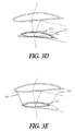
- FIGS. 1A, 1B, 1C, and 1D illustrate Prior Art blades.
- FIG. 2A is a perspective view of a blade according to an example embodiment.
- FIG. 2B is a perspective view of a blade and molding process according to an example embodiment.
- FIGS. 3A, 3B, 3C, 3D, and 3E illustrate various airfoil cross-sections of a blade for which the cavity shape will be determined according to an example embodiment.
- FIG. 4 is a perspective view of a resulting blade profile according to an example embodiment.
- FIGS. 5A, 5B, and 5C illustrate perspective views of a blade and a mounting arrangement according to an example embodiment.
- Airfoil shapes must be selected.
- Basic airfoils for various size classes of wind turbines are known in the art, and are available from sources including the US National Renewable Energy Lab (NREL).
- NREL National Renewable Energy Lab
- An efficient external three-dimensional shape typically incorporates variable chord (distance from leading edge to trailing edge of the airfoil shape) and twist (rotation of the airfoil shape about the long axis of the blade) as a function of radial (spanwise) position along the long axis of the blade.
- Aerodynamic performance data for various airfoils from wind tunnel studies is available in the form of tabulated lift and drag values as a function of angle of attack, from sources including the Selig group at the University of Illinois.
- a suitable planform may be devised by selecting the chord and twist for maximum energy capture.
- Software simulation tools for use in developing a suitable planform are also known, for instance the WT-Perf and FAST codes produced by the National Wind Technology Center.
- an efficient design will feature chord that is widest near the root and tapers continually to a narrow tip, and twist that is near zero angle at the tip, and increases to over 10 degrees near the root.
- blade planform may be optimized from an aerodynamic perspective without reference to blade manufacturing methods
- the blade planform may be a compromise between aerodynamic performance and manufacturing considerations. For instance, in large blades, structural considerations outweigh aerodynamic performance near the root of the blade (the end nearest the hub), and the designer may choose to transition the cross-section of the blade to a circular shape, despite the poor aerodynamic performance of this form. Further adjustments may be made to improve strength, moldability, or appearance.
- thermoplastic resins include glass fiber filled polypropylene, glass fiber filled polyester, and carbon fiber filled polyester.
- injection molding is less well-suited to production of longer blades, for several reasons.
- In-mold cooling time scales with the second power of part thickness, so the greater thickness required for strength and aerodynamic performance in the inboard (root) portions of longer blades leads to long in-mold cooling times and thus high costs, as fewer blades per unit of time may be produced by each mold.
- Thick solid sections of larger blades use large quantities of costly resin, and are difficult to mold, leading to deformation or ‘sinks’ 110 and/or voids 120 in the thick regions, and resulting in poor mechanical strength.
- Designers are thus driven to design blades with root portions that are thinner, narrower, and weaker than aerodynamics and structural considerations would otherwise dictate.
- low-cost manufacture of aerodynamically-optimized single-part wind turbine blades may be performed using economical thermoplastic resins.
- an economical, automatic method produces blades in the range of 1-2 meters in length with favorable aerodynamic profiles and efficient use of inexpensive, durable materials.
- a wind turbine blade 200 is provided with a solid, tipward portion 201 and a hollow, rootward portion 202 which is made hollow by cavity 203 .
- the blade may be produced by injection molding, compression molding, resin transfer molding, or another suitable low-cost molding process.
- the three-dimensional surface 204 that defines cavity 203 may be designed with a continuous taper from the tipward end to the rootward end.
- FIG. 2B An apparatus for producing blade 200 is illustrated in FIG. 2B .
- the outer shape is defined by first and second mold bodies 211 and 212 , mounted in an injection molding machine (press) which is capable of opening and closing the mold, and applying sufficient pressure to perform the molding process.
- the mold bodies may be machined from prehardened steel such as P 20 , or another suitable injection mold tool material. Aluminum may be used for low-cost, short-run tools.
- a third, retractable mold body or core 213 is provided to form the internal cavity of blade 200 . Core 213 may be constrained to move in a direction substantially perpendicular to the action of the injection molding press, and may be mounted to a slide, hydraulic ram, or similar suitable actuating mechanism.
- mold bodies 211 and 212 may be urged together by suitable clamping means, and retractable mold body 213 introduced between them, thereby forming a closed cavity.
- Flowable resin may be introduced into the cavity and solidified, whether by cooling or by chemical cure, thereby forming a solid part which may subsequently be released by retracting body 213 and separating mold bodies 211 and 212 .
- a high-quality aerodynamic blade may be produced quickly and with a practical minimum of material.
- the required amount of resin and the maximum thickness of the part are both significantly lower than would be required for a solid blade of the same length, and thus both material and manufacturing cost are substantially decreased. More specifically, in the case of injection molding, the maximum thickness is decreased by at 2-3 ⁇ or more, resulting in decreased in-mold cooling time by up to 10 ⁇ or more. Additionally, the reduced thickness reduces voids, sinks, and other imperfections.
- the mold bodies 211 , 212 that define the cavity of the mold may be provided with internal cooling channels 214 to admit the flow of water or other cooling medium to maintain mold temperature and draw away the heat that is introduced into the mold during continual operation.
- Internal mold body 213 may likewise be provided with internal cooling channels 215 to admit the flow of water or other coolant to maintain the desired temperature.
- Internal mold body 213 may be fabricated from commercially-available hard copper alloys such as ‘Moldmax’ for increased heat transfer.
- One or more pairs of opposing pins may be provided on mold bodies 211 , 212 and projecting inward toward body 213 , to stabilize the position of body 213 as the resin is injected quickly under high pressure.
- the pins may preferably be elongated along the long axis of the blade to facilitate knitting of the flow around the pins, to avoid creating a weak spot. These pins may leave small openings in the finished part, which may be subsequently plugged or caulked.
- At least one port 220 may be provided at or near the root end communicating with an opening or ‘gate’ into the cavity, to allow injection of molten resin by resin injection system 230 .
- the resin injection system includes a hopper 231 carrying pellets of resin.
- the resin is selected from a variety of commercially available products, based on strength, stiffness, weather and UV resistance, appearance, and cost.
- One suitable material is UV-stabilized 30% glass-filled polypropylene.
- Resin pellets from hopper 231 are introduced into heated barrel 232 , which houses a tapered, helical screw 233 driven by drive system 234 .
- the resin injection system is mounted so as to permit periodic rapid injection of molten resin to port 220 via nozzle 235 .
- multiple gates may be positioned at intervals along the surface of the blade to aid filling the mold. The gates may be individually actuated to optimize the flow direction, for instance to maintain longitudinal fiber orientation while enhancing packing of the mold.
- a hot runner system consisting of heated, high pressure conduits may be adapted to convey molten resin from the resin injection system to the point of injection into the cavity.
- Various other resin injection systems may be used in further embodiments.
- the shape of the internal cavity 203 may be determined.
- the internal mold element 213 may be continuously tapered at a minimum allowable draft angle determined by the molding process (or at a greater angle) to allow its removal from the finished molded blade, and the walls may be of sufficient thickness to provide the blade with the necessary degree of strength to prevent rupture or buckling under load.
- the designer will generally seek to reduce the amount of polymer required to a practical minimum.
- FIG. 3A illustrates two airfoil cross-sections 310 , 320 of a blade for which the cavity shape will be determined.
- the stations are positioned along the longitudinal layout axis 301 of the blade with the tip downward, and the cross-sections have variable twist angle with respect to the plane of rotation, which passes through axes 302 .
- Orthogonal axes 303 extend downwind from the layout axis.
- Station 310 has greater chord and greater twist compared to station 320 .
- the designer may determine the profile defining the cavity at station 310 , for instance by applying a minimum wall thickness offset inward from the station profile 310 to produce cavity profile 313 . While a constant wall thickness is illustrated, variable wall thickness may be preferable in some cases.
- the first cavity profile 313 is projected with the prescribed draft angle (lines 316 ) onto the plane of the second station to produce drafted profile 321 , representing the restriction on the cavity imposed by the requirement for draft.
- a minimum wall thickness offset is applied to the external profile of the second station 320 to produce a second offset profile 322 .
- the actual cavity profile at station 310 is then determined by combining profiles 321 and 322 , taking at all points the inward most curve to produce cavity profile 323 , which simultaneously satisfies the requirements of minimum draft angle between stations and minimum wall thickness at each station.
- the procedure is then repeated from station 320 to the next tipward station, until the cavity profile reaches a minimum practical thickness, whereupon the cavity shape is truncated.
- the final core profiles ( 313 , 323 , etc) are then lofted (as illustrated by loft lines 399 ) to form the final cavity shape.
- the foregoing procedure may be automated by software for rapid determination of the cavity shape.
- the procedure above does not explicitly guarantee that a minimum wall thickness will be realized, because of local concavities in the external shape, but if the stations are close together relative to the local curvature of the blade, the result will be close enough for engineering purposes.
- FIGS. 3A, 3B, 3C, 3D, and 3E will define a core shape that may be successfully retracted from the finished blade with a linear motion
- other core shapes are possible.
- a hollow curved blade may be formed by a core that is removed in an arcuate motion
- a hollow twisted blade may be formed by a core that is removed in a helical motion.
- these alternate procedures may result in a lower-weight part.
- a blade geometry may be developed which may be extracted via the rootward end without separating the first and second mold bodies—i.e. even if the mold bodies were fused together, or a single part.
- the external and internal blade profiles are illustrated in FIG. 4 and may be imported into a commercial 3D modeling program, which can be used to create a 3D solid model of the blade, determine its strength via Finite Element Analysis, and design suitable mold components.
- Injection mold filling simulation software can be used to assess the mold filling properties of the design, with the results used to iterate the design process described above toward a suitable design. While the above procedure captures the essence of the process to develop the cavity shape, the designer may wish to adapt the process, for instance by introducing variable wall thickness according to Finite Element Analysis of strength or mold filling requirements, by varying the draft angle, or by introducing internal ribs.
- the resulting solid models can then be used by tool and die makers to produce mold bodies 211 , 212 , 213 .
- Blade 400 has a cavity 403 formed by molding as described above.
- Blade 400 incorporates molded-in mounting features that facilitate attachment to a central hub.
- holes 460 are arranged in a pattern molded into each side of the blade at the open (root) end, such that the blade may be bolted or through-clamped to a suitably formed hub.
- mounting features, such as holes 460 may be provided in a post-process, for instance by CNC drilling of the plastic material.
- the rootward end of the blade may be configured in a readily moldable shape that interfaces directly to a suitably formed hub.
- the rootward end of the blade 500 consists of upwind side 510 and downwind side 520 , with the downwind side extending further toward the central axis of rotation.
- Sides 510 and 520 may be provided with one or more surfaces 511 , 521 that are aligned parallel to the plane of rotation, and these surfaces may be provided with holes 512 , 522 for alignment and secure attachment to a hub.
- mating hub 530 with bore 531 for attachment to the turbine mainshaft may be configured to receive three blades produced by the methods described herein, and may be provided with one or more surfaces 541 , 551 that are aligned parallel to the plane of rotation, and optionally with bosses 542 to mate with holes 512 .
- each blade 500 is positioned relative to the hub 530 as shown in FIG. 5C , and lowered onto the hub with bosses 542 mating with holes 512 .
- Fasteners may be provided to secure the blade securely to the hub.
- Hub 530 may be designed so as to be readily cast from aluminum, steel, or another suitable alloy, and its shape may be chosen such that the necessary interface features may be readily machined in a single setup.
- Other blade-hub interfaces may be devised, including for instance a system of ridges or tangs on the external surfaces of the blade, while maintaining the moldability of the blade.
- An example method of forming a wind turbine blade comprising:
- a method comprising:
- thermoplastic resin is formed of at least one of thermoplastic resin, fiber-reinforced thermoplastic resin, thermoset resin, and fiber-reinforced thermoset resin.
- a wind turbine blade comprising:
- the wind turbine blade of example 14 wherein the blade is formed of at least one of glass fiber filled polypropylene, glass fiber filled polyester, and carbon fiber filled polyester.
- wind turbine blade of example 12 and further comprising openings near mid-span communicating with the tapered cavity on substantially opposing sides of the blade.
- a mold set for forming a wind turbine blade comprising:
Landscapes
- Engineering & Computer Science (AREA)
- Life Sciences & Earth Sciences (AREA)
- Sustainable Development (AREA)
- Sustainable Energy (AREA)
- Chemical & Material Sciences (AREA)
- Combustion & Propulsion (AREA)
- Mechanical Engineering (AREA)
- General Engineering & Computer Science (AREA)
- Wind Motors (AREA)
- Moulds For Moulding Plastics Or The Like (AREA)
Abstract
Description
-
- bringing a first mold body into proximity with a second mold body;
- positioning a a third, retractable mold body between the first and second mold bodies
- inducing a material to flow in the space between the mold bodies, the flowable material subsequently becoming substantially non-flowable, and
- retracting the third mold body and separating the first and second mold bodies to release a wind turbine blade.
-
- introducing a flowable material in a space between two wind turbine blade mold bodies and a third retractable mold body;
- allowing the flowable material to become substantially non-flowable;
- retracting the third mold body; and
- removing the wind turbine blade from the two wind turbine blade mold bodies.
-
- a rootward portion;
- a tipward portion extending from the roodward portion; and
- a tapered cavity extending from the rootward portion and tapering continuously toward the tipward portion, wherein the wind turbine blade is formed as a single piece of molded material.
-
- a first mold body;
- a second mold body, formed to be brought into proximity with the first mold half to form a wind turbine blade mold; and
- a tapered retractable third mold body for positioning between the first and second mold bodies to form a cavity in a wind turbine blade formed in the wind turbine blade mold.
Claims (15)
Priority Applications (1)
| Application Number | Priority Date | Filing Date | Title |
|---|---|---|---|
| US13/744,246 US9512818B2 (en) | 2012-01-18 | 2013-01-17 | Low-cost molded wind turbine blade |
Applications Claiming Priority (2)
| Application Number | Priority Date | Filing Date | Title |
|---|---|---|---|
| US201261588075P | 2012-01-18 | 2012-01-18 | |
| US13/744,246 US9512818B2 (en) | 2012-01-18 | 2013-01-17 | Low-cost molded wind turbine blade |
Publications (2)
| Publication Number | Publication Date |
|---|---|
| US20130183161A1 US20130183161A1 (en) | 2013-07-18 |
| US9512818B2 true US9512818B2 (en) | 2016-12-06 |
Family
ID=48780087
Family Applications (1)
| Application Number | Title | Priority Date | Filing Date |
|---|---|---|---|
| US13/744,246 Expired - Fee Related US9512818B2 (en) | 2012-01-18 | 2013-01-17 | Low-cost molded wind turbine blade |
Country Status (1)
| Country | Link |
|---|---|
| US (1) | US9512818B2 (en) |
Cited By (13)
| Publication number | Priority date | Publication date | Assignee | Title |
|---|---|---|---|---|
| US10773464B2 (en) | 2017-11-21 | 2020-09-15 | General Electric Company | Method for manufacturing composite airfoils |
| US10821652B2 (en) | 2017-11-21 | 2020-11-03 | General Electric Company | Vacuum forming mold assembly and method for creating a vacuum forming mold assembly |
| US10821696B2 (en) | 2018-03-26 | 2020-11-03 | General Electric Company | Methods for manufacturing flatback airfoils for wind turbine rotor blades |
| US10830206B2 (en) | 2017-02-03 | 2020-11-10 | General Electric Company | Methods for manufacturing wind turbine rotor blades and components thereof |
| US10865769B2 (en) | 2017-11-21 | 2020-12-15 | General Electric Company | Methods for manufacturing wind turbine rotor blade panels having printed grid structures |
| US10913216B2 (en) | 2017-11-21 | 2021-02-09 | General Electric Company | Methods for manufacturing wind turbine rotor blade panels having printed grid structures |
| US10920745B2 (en) | 2017-11-21 | 2021-02-16 | General Electric Company | Wind turbine rotor blade components and methods of manufacturing the same |
| US11035339B2 (en) | 2018-03-26 | 2021-06-15 | General Electric Company | Shear web assembly interconnected with additive manufactured components |
| US11040503B2 (en) | 2017-11-21 | 2021-06-22 | General Electric Company | Apparatus for manufacturing composite airfoils |
| US11098691B2 (en) * | 2017-02-03 | 2021-08-24 | General Electric Company | Methods for manufacturing wind turbine rotor blades and components thereof |
| US11248582B2 (en) | 2017-11-21 | 2022-02-15 | General Electric Company | Multiple material combinations for printed reinforcement structures of rotor blades |
| US11390013B2 (en) | 2017-11-21 | 2022-07-19 | General Electric Company | Vacuum forming mold assembly and associated methods |
| US11668275B2 (en) | 2017-11-21 | 2023-06-06 | General Electric Company | Methods for manufacturing an outer skin of a rotor blade |
Families Citing this family (6)
| Publication number | Priority date | Publication date | Assignee | Title |
|---|---|---|---|---|
| WO2014201018A1 (en) * | 2013-06-10 | 2014-12-18 | Uprise Energy, LLC | Wind energy devices, systems, and methods |
| FR3008920B1 (en) * | 2013-07-29 | 2015-12-25 | Safran | METHOD FOR MANUFACTURING A BLADE IN COMPOSITE MATERIAL WITH INTEGRATED METAL ATTACK FRAME FOR AERONAUTICAL GAS TURBINE ENGINE |
| GB2523414B (en) * | 2014-02-24 | 2016-02-17 | Marine Current Turbines Ltd | Turbine blade and method of manufacture |
| US11629689B2 (en) * | 2014-11-10 | 2023-04-18 | Polytech A/S | Polyurethane material, process for preparing such material and protective cover for wind turbine blade |
| US10690111B2 (en) * | 2016-12-02 | 2020-06-23 | General Electric Company | Wind turbine rotor blade |
| CN112983884A (en) * | 2021-02-09 | 2021-06-18 | 上海东杰高分子材料有限公司 | Preparation method of reaction injection molding fan impeller and fan impeller |
Citations (8)
| Publication number | Priority date | Publication date | Assignee | Title |
|---|---|---|---|---|
| US4698011A (en) * | 1984-07-23 | 1987-10-06 | Aerospatiale Societe Nationale Industrielle | Manufacture of a hollow envelope by winding filamentary material |
| US4720244A (en) * | 1987-05-21 | 1988-01-19 | Hudson Products Corporation | Fan blade for an axial flow fan and method of forming same |
| US4863117A (en) * | 1987-01-07 | 1989-09-05 | Roland Riout | Profiled wing for controlled deformation and application thereof to beating wing aircraft |
| US6158278A (en) * | 1999-09-16 | 2000-12-12 | Hunter Industries, Inc. | Wind speed detector actuator |
| US20030141721A1 (en) * | 2002-01-30 | 2003-07-31 | Bartlett Lexington P. | Wind power system |
| US20060257240A1 (en) * | 2005-05-13 | 2006-11-16 | Naskali Pertti H | Helical wind turbine |
| US20090324412A1 (en) * | 2003-10-06 | 2009-12-31 | Bart Roorda | Rotor for use in a wind turbine, and method for making the rotor |
| US8007705B2 (en) * | 2009-03-14 | 2011-08-30 | Raytheon Company | Method of manufacture of one-piece composite parts using a two-piece form including a shaped polymer that does not draw with a rigid insert designed to draw |
-
2013
- 2013-01-17 US US13/744,246 patent/US9512818B2/en not_active Expired - Fee Related
Patent Citations (8)
| Publication number | Priority date | Publication date | Assignee | Title |
|---|---|---|---|---|
| US4698011A (en) * | 1984-07-23 | 1987-10-06 | Aerospatiale Societe Nationale Industrielle | Manufacture of a hollow envelope by winding filamentary material |
| US4863117A (en) * | 1987-01-07 | 1989-09-05 | Roland Riout | Profiled wing for controlled deformation and application thereof to beating wing aircraft |
| US4720244A (en) * | 1987-05-21 | 1988-01-19 | Hudson Products Corporation | Fan blade for an axial flow fan and method of forming same |
| US6158278A (en) * | 1999-09-16 | 2000-12-12 | Hunter Industries, Inc. | Wind speed detector actuator |
| US20030141721A1 (en) * | 2002-01-30 | 2003-07-31 | Bartlett Lexington P. | Wind power system |
| US20090324412A1 (en) * | 2003-10-06 | 2009-12-31 | Bart Roorda | Rotor for use in a wind turbine, and method for making the rotor |
| US20060257240A1 (en) * | 2005-05-13 | 2006-11-16 | Naskali Pertti H | Helical wind turbine |
| US8007705B2 (en) * | 2009-03-14 | 2011-08-30 | Raytheon Company | Method of manufacture of one-piece composite parts using a two-piece form including a shaped polymer that does not draw with a rigid insert designed to draw |
Cited By (14)
| Publication number | Priority date | Publication date | Assignee | Title |
|---|---|---|---|---|
| US11098691B2 (en) * | 2017-02-03 | 2021-08-24 | General Electric Company | Methods for manufacturing wind turbine rotor blades and components thereof |
| US10830206B2 (en) | 2017-02-03 | 2020-11-10 | General Electric Company | Methods for manufacturing wind turbine rotor blades and components thereof |
| US11548246B2 (en) | 2017-11-21 | 2023-01-10 | General Electric Company | Apparatus for manufacturing composite airfoils |
| US10865769B2 (en) | 2017-11-21 | 2020-12-15 | General Electric Company | Methods for manufacturing wind turbine rotor blade panels having printed grid structures |
| US10913216B2 (en) | 2017-11-21 | 2021-02-09 | General Electric Company | Methods for manufacturing wind turbine rotor blade panels having printed grid structures |
| US11040503B2 (en) | 2017-11-21 | 2021-06-22 | General Electric Company | Apparatus for manufacturing composite airfoils |
| US10920745B2 (en) | 2017-11-21 | 2021-02-16 | General Electric Company | Wind turbine rotor blade components and methods of manufacturing the same |
| US10821652B2 (en) | 2017-11-21 | 2020-11-03 | General Electric Company | Vacuum forming mold assembly and method for creating a vacuum forming mold assembly |
| US10773464B2 (en) | 2017-11-21 | 2020-09-15 | General Electric Company | Method for manufacturing composite airfoils |
| US11248582B2 (en) | 2017-11-21 | 2022-02-15 | General Electric Company | Multiple material combinations for printed reinforcement structures of rotor blades |
| US11390013B2 (en) | 2017-11-21 | 2022-07-19 | General Electric Company | Vacuum forming mold assembly and associated methods |
| US11668275B2 (en) | 2017-11-21 | 2023-06-06 | General Electric Company | Methods for manufacturing an outer skin of a rotor blade |
| US10821696B2 (en) | 2018-03-26 | 2020-11-03 | General Electric Company | Methods for manufacturing flatback airfoils for wind turbine rotor blades |
| US11035339B2 (en) | 2018-03-26 | 2021-06-15 | General Electric Company | Shear web assembly interconnected with additive manufactured components |
Also Published As
| Publication number | Publication date |
|---|---|
| US20130183161A1 (en) | 2013-07-18 |
Similar Documents
| Publication | Publication Date | Title |
|---|---|---|
| US9512818B2 (en) | Low-cost molded wind turbine blade | |
| WO2014096004A3 (en) | A method of manufacturing an aerodynamic shell part for a wind turbine blade | |
| US9067345B2 (en) | Mold for manufacture of fiber composite parts and method of manufacture of fiber composite parts with such a mold | |
| CN106553357A (en) | Hollow multi-cavity abnormal shape surface composite material complex structural member integral forming technique | |
| CN111655465B (en) | Apparatus for manufacturing composite airfoils | |
| CN111655466B (en) | Apparatus and method for manufacturing composite airfoils | |
| CN102963493B (en) | Composite plastic boat body and compression molding method thereof | |
| CN110892150B (en) | Method of making a wind turbine blade and wind turbine blade therefor | |
| CN102248618A (en) | Device and partial mold for the production of rotor blades for wind power plants and methods for the production | |
| CN103587120A (en) | Vane die manufacturing system and vane die manufacturing method | |
| CN206936290U (en) | A kind of precoated sand mould of disjunctor bracket | |
| US20210178680A1 (en) | Moveable Molding Assembly for Use with Additive Manufacturing | |
| CN105517785A (en) | Wind turbine blade | |
| US9333555B2 (en) | Manufacturing method of a component of a split blade of a wind turbine | |
| WO2022023045A1 (en) | Winglet and winglet cover assembly | |
| CN106217697B (en) | A kind of molding die and preparation method thereof of composite material multi-rotor unmanned aerial vehicle horn | |
| CN101985234B (en) | Processing technology of wax mould of nozzle ring | |
| CN113997605A (en) | Forming die and demolding method for composite material part of variable-section closed-angle cap-type pipeline | |
| CN206999679U (en) | Carbon fiber dual platen reinforced structure part | |
| CN105196566A (en) | Mould and method for manufacturing wind generating set blade | |
| CN209616384U (en) | A kind of multi-rotor unmanned aerial vehicle composite material undercarriage tee joint forming die | |
| CN216443110U (en) | Forming die for composite material parts of variable-cross-section closed-angle cap type pipeline | |
| CN212707597U (en) | Quick forming die of sectional type fan blade | |
| US20190152127A1 (en) | Vacuum Forming Mold Assembly and Associated Methods | |
| CN222662734U (en) | A combined mold for manufacturing composite root ribs of light aircraft |
Legal Events
| Date | Code | Title | Description |
|---|---|---|---|
| AS | Assignment |
Owner name: PIKA ENERGY LLC, MAINE Free format text: ASSIGNMENT OF ASSIGNORS INTEREST;ASSIGNORS:RICHTMAN, KEITH THOMAS;POLITO, BENJAMIN FRANCIS;KAUFMAN, JOSHUA DANIEL;REEL/FRAME:030114/0197 Effective date: 20130117 |
|
| FEPP | Fee payment procedure |
Free format text: PAYOR NUMBER ASSIGNED (ORIGINAL EVENT CODE: ASPN); ENTITY STATUS OF PATENT OWNER: LARGE ENTITY |
|
| STCF | Information on status: patent grant |
Free format text: PATENTED CASE |
|
| AS | Assignment |
Owner name: PIKA ENERGY, INC., MAINE Free format text: ASSIGNMENT OF ASSIGNORS INTEREST;ASSIGNOR:PIKA ENERGY LLC;REEL/FRAME:041372/0598 Effective date: 20170202 |
|
| AS | Assignment |
Owner name: PIKA ENERGY, INC., MAINE Free format text: NUNC PRO TUNC ASSIGNMENT;ASSIGNOR:PIKA ENERGY LLC;REEL/FRAME:048957/0819 Effective date: 20190422 |
|
| AS | Assignment |
Owner name: PIKA ENERGY, INC., MAINE Free format text: CHANGE OF NAME;ASSIGNOR:PIKA ENERGY LLC;REEL/FRAME:048973/0571 Effective date: 20130401 |
|
| AS | Assignment |
Owner name: BANK OF AMERICA, N.A., WISCONSIN Free format text: SECURITY AGREEMENT;ASSIGNOR:PIKA ENERGY, INC.;REEL/FRAME:051213/0228 Effective date: 20191206 |
|
| FEPP | Fee payment procedure |
Free format text: ENTITY STATUS SET TO UNDISCOUNTED (ORIGINAL EVENT CODE: BIG.); ENTITY STATUS OF PATENT OWNER: LARGE ENTITY |
|
| AS | Assignment |
Owner name: JPMORGAN CHASE BANK, N.A., AS ADMINISTRATIVE AGENT Free format text: SECURITY INTEREST;ASSIGNOR:PIKA ENERGY, INC.;REEL/FRAME:051232/0001 Effective date: 20191206 Owner name: JPMORGAN CHASE BANK, N.A., AS ADMINISTRATIVE AGENT, ILLINOIS Free format text: SECURITY INTEREST;ASSIGNOR:PIKA ENERGY, INC.;REEL/FRAME:051232/0001 Effective date: 20191206 |
|
| FEPP | Fee payment procedure |
Free format text: MAINTENANCE FEE REMINDER MAILED (ORIGINAL EVENT CODE: REM.); ENTITY STATUS OF PATENT OWNER: LARGE ENTITY |
|
| LAPS | Lapse for failure to pay maintenance fees |
Free format text: PATENT EXPIRED FOR FAILURE TO PAY MAINTENANCE FEES (ORIGINAL EVENT CODE: EXP.); ENTITY STATUS OF PATENT OWNER: LARGE ENTITY |
|
| STCH | Information on status: patent discontinuation |
Free format text: PATENT EXPIRED DUE TO NONPAYMENT OF MAINTENANCE FEES UNDER 37 CFR 1.362 |
|
| FP | Lapsed due to failure to pay maintenance fee |
Effective date: 20201206 |
|
| AS | Assignment |
Owner name: GENERAC MOBILE PRODUCTS, LLC (F/K/A MAGNUM POWER PRODUCTS, LLC), WISCONSIN Free format text: RELEASE BY SECURED PARTY;ASSIGNOR:BANK OF AMERICA, N.A.;REEL/FRAME:060541/0840 Effective date: 20220629 Owner name: PIKA ENERGY, INC., MAINE Free format text: RELEASE BY SECURED PARTY;ASSIGNOR:BANK OF AMERICA, N.A.;REEL/FRAME:060541/0840 Effective date: 20220629 Owner name: POWER MANAGEMENT HOLDINGS (U.S.), INC., COLORADO Free format text: RELEASE BY SECURED PARTY;ASSIGNOR:BANK OF AMERICA, N.A.;REEL/FRAME:060541/0840 Effective date: 20220629 Owner name: GENERAC POWER SYSTEMS, INC., WISCONSIN Free format text: RELEASE BY SECURED PARTY;ASSIGNOR:BANK OF AMERICA, N.A.;REEL/FRAME:060541/0840 Effective date: 20220629 |