US9511794B2 - Electric power steering system and method for processing fail-safe of electronic control unit - Google Patents
Electric power steering system and method for processing fail-safe of electronic control unit Download PDFInfo
- Publication number
- US9511794B2 US9511794B2 US14/750,906 US201514750906A US9511794B2 US 9511794 B2 US9511794 B2 US 9511794B2 US 201514750906 A US201514750906 A US 201514750906A US 9511794 B2 US9511794 B2 US 9511794B2
- Authority
- US
- United States
- Prior art keywords
- motor
- steering
- angle value
- angular velocity
- electric power
- Prior art date
- Legal status (The legal status is an assumption and is not a legal conclusion. Google has not performed a legal analysis and makes no representation as to the accuracy of the status listed.)
- Active
Links
Images


Classifications
-
- B—PERFORMING OPERATIONS; TRANSPORTING
- B62—LAND VEHICLES FOR TRAVELLING OTHERWISE THAN ON RAILS
- B62D—MOTOR VEHICLES; TRAILERS
- B62D5/00—Power-assisted or power-driven steering
- B62D5/04—Power-assisted or power-driven steering electrical, e.g. using an electric servo-motor connected to, or forming part of, the steering gear
- B62D5/0457—Power-assisted or power-driven steering electrical, e.g. using an electric servo-motor connected to, or forming part of, the steering gear characterised by control features of the drive means as such
- B62D5/046—Controlling the motor
- B62D5/0463—Controlling the motor calculating assisting torque from the motor based on driver input
-
- B—PERFORMING OPERATIONS; TRANSPORTING
- B62—LAND VEHICLES FOR TRAVELLING OTHERWISE THAN ON RAILS
- B62D—MOTOR VEHICLES; TRAILERS
- B62D5/00—Power-assisted or power-driven steering
- B62D5/04—Power-assisted or power-driven steering electrical, e.g. using an electric servo-motor connected to, or forming part of, the steering gear
- B62D5/0457—Power-assisted or power-driven steering electrical, e.g. using an electric servo-motor connected to, or forming part of, the steering gear characterised by control features of the drive means as such
- B62D5/0481—Power-assisted or power-driven steering electrical, e.g. using an electric servo-motor connected to, or forming part of, the steering gear characterised by control features of the drive means as such monitoring the steering system, e.g. failures
- B62D5/0484—Power-assisted or power-driven steering electrical, e.g. using an electric servo-motor connected to, or forming part of, the steering gear characterised by control features of the drive means as such monitoring the steering system, e.g. failures for reaction to failures, e.g. limp home
-
- B—PERFORMING OPERATIONS; TRANSPORTING
- B62—LAND VEHICLES FOR TRAVELLING OTHERWISE THAN ON RAILS
- B62D—MOTOR VEHICLES; TRAILERS
- B62D5/00—Power-assisted or power-driven steering
- B62D5/04—Power-assisted or power-driven steering electrical, e.g. using an electric servo-motor connected to, or forming part of, the steering gear
- B62D5/0457—Power-assisted or power-driven steering electrical, e.g. using an electric servo-motor connected to, or forming part of, the steering gear characterised by control features of the drive means as such
- B62D5/0481—Power-assisted or power-driven steering electrical, e.g. using an electric servo-motor connected to, or forming part of, the steering gear characterised by control features of the drive means as such monitoring the steering system, e.g. failures
- B62D5/049—Power-assisted or power-driven steering electrical, e.g. using an electric servo-motor connected to, or forming part of, the steering gear characterised by control features of the drive means as such monitoring the steering system, e.g. failures detecting sensor failures
Definitions
- the present invention relates to an electric power steering system and a method of processing a fail-safe of an electronic control unit.
- an electric power steering system provides a steering assist force by driving an electric motor when a driver operates a steering wheel of a vehicle so as to reduce the driver's steering burden.
- the Electronic Control Unit (ECU) of the electric power steering system should receive a steering torque signal—a signal generated by measuring the steering torque generated by the user to operate the steering wheel—from a torque sensor.
- the torque sensor refers to a device configured to convert the steering torque of the steering wheel generated by the driver's steering intention into an electric signal.
- the torque sensor is installed to the electric power steering system so as to measure the torque of the steering wheel.
- one fail-safe method for a failure of the torque sensor is to stop the operation of the electric power steering system when the failure of the torque sensor occurs, and then switch the steering system into a manual mode, for example.
- an object of the present invention is to provide an electric power steering system and method, in which, when the torque sensor fails, a target angular velocity of the electric motor is estimated using steering angle information and motor rotation angle information, and a steering assist force is generated by a motor driving current so as to cause a current motor angular velocity to converge to the estimated target angular velocity.
- the present invention provides an electric power steering system.
- the system includes: a torque sensor configured to detect a steering torque value of a steering wheel; a steering angle sensor configured to detect a steering angle value of the steering wheel; a motor position sensor configured to detect a motor rotation angle value which is a rotated angle of a driving shaft of an electric motor; and an electronic control unit configured, when the torque sensor is normal, to generate a first steering assist current for controlling a driving force of the electric motor using the steering torque value, and when the torque sensor fails, to estimate a target motor angular velocity of the electric motor using the steering angle value and the motor rotation angle value and to generate a second steering assist current so as to cause a current motor angular velocity of the electric motor to converge to the target motor angular velocity.
- the present invention provides a method for processing a fail-safe of an electronic control unit in an electric power steering system.
- the method includes a basic control performing step of generating a first steering assist current using a steering torque value detected by a torque sensor; a sensor failure detecting step of detecting a failure of the torque sensor while the basic control is performed; a target motor angular velocity estimating step of estimating a target motor angular velocity of the electric motor using a steering angle value of a steering wheel and a motor rotation angle value of an electric motor; and a fail-safe control step of calculating a current motor angular velocity of the electric motor, and generating a second steering assist current so as to cause the current motor angular velocity to converge to the target motor angular velocity.
- the electric power steering system is not switched to the manual mode unlike the prior art, and the steering assist force is provided through the control of the motor angular velocity of the electric motor. Therefore, it is possible to prevent the steering assist force from being lost momentarily when the torque sensor fails.
- a fail-safe is processed through the control of the motor angular velocity of the electric motor, i.e. using a motor angular velocity which is a differential value of the motor rotation angle. Therefore, the motor rotation angle can be controlled such that no overshoot occurs for the target motor rotation angle, which can prevent occurrence of self-steering which is caused by the overshoot of the motor rotation angle.
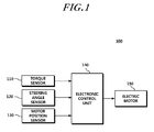
- FIG. 1 is a block diagram briefly illustrating a configuration of an electric power steering system according to an embodiment of the present invention
- FIG. 2 is a block diagram briefly illustrating a configuration of an electronic control unit included in the electric power steering system according to the embodiment of the present invention
- FIG. 3 is a view for describing an effect of a fail-safe control executed by the electronic control unit when the torque sensor fails in the electric power steering system according to the embodiment of the present invention.
- FIG. 4 is a flowchart illustrating a fail-safe processing process executed by the electronic control unit when the torque sensor in the electric power steering system according to the present invention.
- first”, “second”, “A”, “B”, “(a)”, “(b)” and the like may be used. These terms are merely used to distinguish one structural element from other structural elements, and a property, an order, a sequence and the like of a corresponding structural element are not limited by the term. It should be noted that if it is described in the specification that one component is “connected,” “coupled” or “joined” to another component, a third component may be “connected,” “coupled,” and “joined” between the first and second components, although the first component may be directly connected, coupled or joined to the second component.
- FIG. 1 is a block diagram briefly illustrating a configuration of an electric power steering system according to an embodiment of the present invention.
- an electric power steering system 100 includes a torque sensor 110 , a steering angle sensor 120 , a motor position sensor 130 , an electronic control unit 140 , and an electric motor 150 .
- the torque sensor 110 detects a steering torque value of a steering wheel.
- the torque sensor 110 senses a steering torque through the relative rotational displacement of the input shaft and the output shaft of a steering column (not illustrated) according to the rotation of the steering wheel, generates a steering torque signal which is an electric signal, and transmits the generated steering torque signal to the electronic control unit 140 to be described later.
- the steering angle sensor 120 is arranged on the input shaft of the steering column (not illustrated) so as to detect a steering angle value that is a rotation angle of the steering wheel rotated by the driver's operation, and transmit the detected steering angle value to the electronic control unit 140 to be described later.
- the motor position sensor 130 detects the rotation position of the electric motor 150 , i.e. the motor rotation angle value which is the rotated angle of the motor shaft of the electric motor 150 , and transmits the detected motor rotation angle value to the electronic control unit 140 to be described later.
- the electronic control unit 140 receives information required for a steering control from a plurality of sensors including the torque sensor 110 and the steering angle sensor 120 , and generates a steering assist current considering the received information, thereby controlling the driving force of the electric motor 150 .
- the electronic control unit 140 when the torque sensor 110 is normal, the electronic control unit 140 generates a first steering assist current using the steering torque value detected by the torque sensor 110 so as to control the driving force of the electric motor 150 .
- the electronic control unit 140 estimates the target motor angular velocity of the electric motor 150 using the steering angle value received from the steering angle sensor 120 and the motor rotation angle value received from the motor position sensor 130 , and generates a second steering assist current so as to cause the current motor angular velocity of the electric motor 150 to converge to the target motor angular velocity.
- the electronic control unit 140 may generate the second steering assist current.
- the electronic control unit 140 may generate the second steering assist current when the torque sensor 110 fails regardless of the state of the ignition switch of the vehicle.
- the electronic control unit 140 calculates an estimated steering angle value by multiplying a deceleration ratio of a reducer mechanically connected to the motor shaft of the electric motor 150 by a motor rotation angle value, then calculates an angular deviation by subtracting the estimated steering angle value from a steering angle value received from the steering angle sensor 120 , and extracts a target motor angular velocity corresponding to the angular deviation from a previously stored target motor angular velocity table so as to estimate the motor angular velocity.
- Steering Angle Value ⁇ (Motor Rotation Angle Value*Deceleration Ratio of Reducer) Equation 1
- the electronic control unit 140 may estimate the target motor angular velocity of the electric motor 150 using the steering angle value and the motor rotation angle value detected by the steering angle sensor 120 and the motor position sensor 130 at pre-set sampling intervals.
- the steering angle sensor 120 may detect the steering angle value at a first pre-set sampling interval
- the motor position sensor 130 may detect the motor rotation angle value at a second pre-set sampling interval.
- the first sampling interval and the second interval may be set to be the same or different from each other.
- the steering angle value and the motor rotation angle value used when estimating the target motor angular velocity are the steering angle value and the motor rotation angle value which are detected by the steering angle sensor 120 and the motor position sensor 130 at the same time.
- the electronic control unit 140 may calculate the angular deviation using a steering angle value detected at a time point closest to the time point when calculating the angular deviation among one or more steering angle values detected at the first sampling interval and a motor rotation angle value detected at a time point closest to the time point when calculating the angular deviation among one or more motor rotation angle values detected at the second sampling interval.
- the steering angle sensor 120 detects the steering angle value at the interval of 10 ms. That is, the steering angle sensor 120 detects a first steering angle value at 0 ms, detects a steering angle value at 10 ms, and detects one or more steering angle values at 10 ms interval in the same manner.
- the motor position sensor 130 detects one or more motor rotation angle values at the interval of 1 ms from 0 ms.
- the electronic control unit 140 may calculate the angular deviation using the first steering angle value detected at a time point closest to the corresponding time point and the motor rotation angle value at 8 ms. Similarly, in the case where the time point when calculating the above-described angular deviation is 12 ms, the electronic control unit 140 may calculate the angular deviation using the second steering angle value detected at a time point closest to the corresponding time point and the motor rotation angle value detected at 12 ms.
- the target motor angular velocity table includes one or more target motor angular velocities that correspond to one or more angular deviations, respectively.
- the target motor angular velocity table may be prepared through a plurality of real vehicle tests.
- the electronic control unit 140 may generate the second steering assist current so as to cause the current motor angular velocity of the electric motor 150 to converge to the target motor angular velocity estimated using the steering angle value and the motor rotation angle value as described above, and may control the occurrence of a failure alarm signal for the failure of the torque sensor 110 .
- the electronic control unit 140 may transmit a failure alarm signal for the failure of the torque sensor 110 to the dash board of the vehicle.
- the electronic control unit 140 as described above may include, as illustrated in FIG. 2 , a first steering control unit 142 configured to generate the first steering assist current using the steering torque value and multiple pieces of sensor information when the torque sensor 110 fails, and a second steering control unit 144 configured to estimate the target angular velocity of the electric motor 150 using the steering angle value and the motor rotation angle value when the torque sensor 110 fails, and to generate a second steering assist current so as to cause the current motor angular velocity of the electric motor 150 to converge to the motor angular velocity.
- the electric motor 150 When the torque sensor 110 is normal, the electric motor 150 generates a steering assist force by receiving the first steering assist current supplied from the electronic control unit 140 , and when the torque sensor 110 fails, the electronic motor 150 generates a second steering assist force by receiving the second steering assist current supplied from the electronic control unit 140 .
- the second steering assist current may be determined to correspond to the target motor angular velocity.
- the second steering assist current may be determined by a current value required for driving the electric motor 150 to the target motor angular velocity.
- the steering assist force is provided through the control of the motor angular velocity of the electric motor 150 without switching the electric power steering system 100 to the manual mode unlike the prior art. Therefore, it is possible to prevent the steering assist force from being momentarily lost when the torque sensor 110 fails.
- a fail-safe is processed through the control of the motor angular velocity of the electric motor 150 , i.e. using a motor angular velocity which is a differential value of the motor rotation angle. Therefore, the motor rotation angle can be controlled such that no overshoot occurs for the target motor rotation angle as illustrated in FIG. 3 , which can prevent occurrence of self-steering which is caused by the overshoot of the motor rotation angle.
- FIG. 4 is a flowchart illustrating a fail-safe processing process executed by the electronic control unit when the torque sensor in the electric power steering system according to the present invention.
- the electronic control unit 140 continuously monitors whether the torque sensor 110 fails, and when the torque sensor 110 is normal, the electronic control unit 140 generates a first steering assist current using the steering torque value detected by the torque sensor 110 (S 410 , S 420 ).
- step S 410 when it is determined that the torque sensor 110 fails, the electronic control unit calculates an estimated steering angle value by multiplying a deceleration ratio of the reducer mechanically connected to the motor shaft of the electric motor 150 by a motor rotation angle value as expressed by Equation 1, and then calculates an angular deviation by subtracting the estimated steering angle value from a steering angle value received from the steering angle sensor 120 (S 430 ).
- the electronic control unit 140 estimates the target motor angular velocity in a manner of extracting the target motor angular velocity corresponding to the angular deviation from the previously stored target motor angular velocity table (S 440 ).
- the electronic control unit 140 may calculate the angular deviation using a steering angle value detected at a time point closest to the time point when calculating the angular deviation among one or more steering angle values detected at the first sampling interval and a motor rotation angle value detected at a time point closest to the time point when calculating the angular deviation among one or more motor rotation angle values detected at the second sampling interval.
- the electronic control unit 140 may calculate the current motor angular velocity of the electric motor 150 using the motor rotation angle value, and may generate a second steering assist current so as to cause the calculated current motor angular velocity to converge to the target angular velocity extracted from the target motor angular velocity table. That is, a control is performed to increase or decrease the second steering assist current by a difference between the current motor angular velocity and the motor angular velocity (S 450 ).
- the electronic control unit 140 may control occurrence of a failure alarm signal for the failure of the torque sensor 110 .
- the electronic control unit 140 performs the above-described fail-safe processing until the ignition switch of the vehicle is switched from the ON state to the OFF state, and when the ignition switch is switched to the OFF state, the electronic control unit 140 terminates the fail-safe processing (S 460 ).
Landscapes
- Engineering & Computer Science (AREA)
- Chemical & Material Sciences (AREA)
- Combustion & Propulsion (AREA)
- Transportation (AREA)
- Mechanical Engineering (AREA)
- Steering Control In Accordance With Driving Conditions (AREA)
- Power Steering Mechanism (AREA)
Abstract
Description
Steering Angle Value−(Motor Rotation Angle Value*Deceleration Ratio of Reducer)
Claims (11)
Applications Claiming Priority (2)
| Application Number | Priority Date | Filing Date | Title |
|---|---|---|---|
| KR10-2014-0077888 | 2014-06-25 | ||
| KR1020140077888A KR101951247B1 (en) | 2014-06-25 | 2014-06-25 | Electric power steering system and method for processing failsafe of electronic control unit |
Publications (2)
| Publication Number | Publication Date |
|---|---|
| US20150375776A1 US20150375776A1 (en) | 2015-12-31 |
| US9511794B2 true US9511794B2 (en) | 2016-12-06 |
Family
ID=54929656
Family Applications (1)
| Application Number | Title | Priority Date | Filing Date |
|---|---|---|---|
| US14/750,906 Active US9511794B2 (en) | 2014-06-25 | 2015-06-25 | Electric power steering system and method for processing fail-safe of electronic control unit |
Country Status (4)
| Country | Link |
|---|---|
| US (1) | US9511794B2 (en) |
| KR (1) | KR101951247B1 (en) |
| CN (1) | CN105313948B (en) |
| DE (1) | DE102015008140B4 (en) |
Cited By (1)
| Publication number | Priority date | Publication date | Assignee | Title |
|---|---|---|---|---|
| US10661828B2 (en) * | 2017-04-12 | 2020-05-26 | Hyundai Motor Company | System and method for estimating steering torque |
Families Citing this family (13)
| Publication number | Priority date | Publication date | Assignee | Title |
|---|---|---|---|---|
| CN106956717A (en) * | 2016-01-11 | 2017-07-18 | 上银科技股份有限公司 | System and method for detecting fault of steering wheel angle sensor |
| US9896123B2 (en) * | 2016-01-29 | 2018-02-20 | Tk Holdings Inc. | Systems and methods for detecting steering wheel contact |
| KR20180042907A (en) * | 2016-10-19 | 2018-04-27 | 현대자동차주식회사 | Control method of Motor Driven Power Steering System |
| KR102440668B1 (en) * | 2016-10-19 | 2022-09-05 | 현대자동차주식회사 | Control method of Motor Driven Power Steering System in case of malfunction torque sensor |
| US10589780B2 (en) * | 2016-11-07 | 2020-03-17 | Nsk Ltd. | Electric power steering apparatus |
| KR102557830B1 (en) * | 2017-01-02 | 2023-07-24 | 현대모비스 주식회사 | Steering return control apparatus of motor driven power steering and method thereof |
| US10960922B2 (en) * | 2017-01-31 | 2021-03-30 | Steering Solutions Ip Holding Corporation | Fault tolerant field oriented control for electric power steering |
| KR102205254B1 (en) * | 2017-04-27 | 2021-01-21 | 현대모비스 주식회사 | Apparatus and method for controlling a motor of motor driven power steering system |
| US10773749B2 (en) * | 2017-10-17 | 2020-09-15 | Steering Solutions Ip Holding Corporation | Driver warning in electric power steering systems |
| US11440580B2 (en) * | 2018-06-01 | 2022-09-13 | Mando Corporation | Electric power steering apparatus and control method for the same, apparatus for synchronization dual steering motor and method i'hereof |
| DE102019212618A1 (en) * | 2019-08-22 | 2021-02-25 | Thyssenkrupp Ag | Motor vehicle power steering |
| CN116118851A (en) * | 2022-12-15 | 2023-05-16 | 合众新能源汽车股份有限公司 | Steering wheel steering power assisting method and device |
| CN117208072B (en) * | 2023-08-03 | 2026-04-24 | 博世华域转向系统有限公司 | Methods for handling torque sensor failure in electric power steering systems |
Citations (3)
| Publication number | Priority date | Publication date | Assignee | Title |
|---|---|---|---|---|
| US20090026004A1 (en) * | 2007-07-25 | 2009-01-29 | Denso Corporation | Power steering apparatus having failure detection device for rotation angle sensors |
| US20120046832A1 (en) * | 2010-08-23 | 2012-02-23 | Jtekt Corporation | Vehicle steering system |
| US20130261894A1 (en) * | 2010-11-18 | 2013-10-03 | Nsk Ltd. | Electric Power Steering Apparatus |
Family Cites Families (6)
| Publication number | Priority date | Publication date | Assignee | Title |
|---|---|---|---|---|
| JP3418098B2 (en) * | 1997-08-27 | 2003-06-16 | 本田技研工業株式会社 | Electric power steering device |
| KR20020043069A (en) * | 2000-12-01 | 2002-06-08 | 밍 루 | Apparatus for controlling a motor in electronic power steering system |
| JP4007200B2 (en) * | 2003-01-20 | 2007-11-14 | 株式会社ジェイテクト | Electric power steering device |
| JP4685471B2 (en) * | 2005-02-24 | 2011-05-18 | 株式会社ショーワ | Electric power steering device |
| JP2009269540A (en) | 2008-05-09 | 2009-11-19 | Jtekt Corp | Electric power steering device |
| MX343649B (en) | 2011-09-21 | 2016-11-14 | Miller Herman Inc | Bi-level headrest, body support structure and method of supporting a user's cranium. |
-
2014
- 2014-06-25 KR KR1020140077888A patent/KR101951247B1/en active Active
-
2015
- 2015-06-24 DE DE102015008140.3A patent/DE102015008140B4/en active Active
- 2015-06-25 US US14/750,906 patent/US9511794B2/en active Active
- 2015-06-25 CN CN201510363788.7A patent/CN105313948B/en active Active
Patent Citations (3)
| Publication number | Priority date | Publication date | Assignee | Title |
|---|---|---|---|---|
| US20090026004A1 (en) * | 2007-07-25 | 2009-01-29 | Denso Corporation | Power steering apparatus having failure detection device for rotation angle sensors |
| US20120046832A1 (en) * | 2010-08-23 | 2012-02-23 | Jtekt Corporation | Vehicle steering system |
| US20130261894A1 (en) * | 2010-11-18 | 2013-10-03 | Nsk Ltd. | Electric Power Steering Apparatus |
Cited By (1)
| Publication number | Priority date | Publication date | Assignee | Title |
|---|---|---|---|---|
| US10661828B2 (en) * | 2017-04-12 | 2020-05-26 | Hyundai Motor Company | System and method for estimating steering torque |
Also Published As
| Publication number | Publication date |
|---|---|
| KR101951247B1 (en) | 2019-02-22 |
| US20150375776A1 (en) | 2015-12-31 |
| KR20160000617A (en) | 2016-01-05 |
| CN105313948B (en) | 2017-12-12 |
| DE102015008140A1 (en) | 2016-02-18 |
| CN105313948A (en) | 2016-02-10 |
| DE102015008140B4 (en) | 2022-10-13 |
Similar Documents
| Publication | Publication Date | Title |
|---|---|---|
| US9511794B2 (en) | Electric power steering system and method for processing fail-safe of electronic control unit | |
| US11097770B2 (en) | Electric power steering apparatus | |
| US9522696B2 (en) | Method and apparatus for controlling electric power steering | |
| US9002579B2 (en) | Steering assist device | |
| JP2017077830A (en) | Electric power steering device | |
| US9932067B2 (en) | Electric power steering apparatus | |
| EP2810853A2 (en) | Actuator control apparatus | |
| CN106029471A (en) | Power steering device and power steering device control device | |
| US10666179B2 (en) | Control system | |
| EP2754601A1 (en) | Motor control device and electric power steering apparatus | |
| US9540044B2 (en) | Hand wheel angle from vehicle dynamic sensors or wheel speeds | |
| JP5181563B2 (en) | Vehicle steering system | |
| JP6413589B2 (en) | Vehicle steering system | |
| US20150151785A1 (en) | Method and apparatus for detecting motor error of motor driven power steering | |
| KR102124521B1 (en) | Electronic control unit and method for estimating column torque | |
| WO2017068896A1 (en) | Electric power steering device | |
| KR101962647B1 (en) | Steer by Wire System and Controlling Method Thereof | |
| JP5946497B2 (en) | Steering control device | |
| KR20160036756A (en) | Fault diagnostic apparatus and control method of motor driven power steering | |
| EP3056409A1 (en) | Torque steering mitigation for electric power steering | |
| JP2015047878A (en) | Electric power steering device | |
| KR20150074522A (en) | Steering control system | |
| JP2013126792A (en) | Vehicle steering device | |
| JP2015150998A (en) | Steer-by-wire steering device | |
| KR20150082910A (en) | Steering control apparatus and steering control method for changing electric current map following friction level of reduction gear |
Legal Events
| Date | Code | Title | Description |
|---|---|---|---|
| AS | Assignment |
Owner name: MANDO CORPORATION, KOREA, REPUBLIC OF Free format text: ASSIGNMENT OF ASSIGNORS INTEREST;ASSIGNOR:HONG, SEUNG GYU;REEL/FRAME:035909/0561 Effective date: 20150623 |
|
| STCF | Information on status: patent grant |
Free format text: PATENTED CASE |
|
| FEPP | Fee payment procedure |
Free format text: PAYOR NUMBER ASSIGNED (ORIGINAL EVENT CODE: ASPN); ENTITY STATUS OF PATENT OWNER: LARGE ENTITY |
|
| MAFP | Maintenance fee payment |
Free format text: PAYMENT OF MAINTENANCE FEE, 4TH YEAR, LARGE ENTITY (ORIGINAL EVENT CODE: M1551); ENTITY STATUS OF PATENT OWNER: LARGE ENTITY Year of fee payment: 4 |
|
| AS | Assignment |
Owner name: HL MANDO CORPORATION, KOREA, REPUBLIC OF Free format text: CHANGE OF NAME;ASSIGNOR:MANDO CORPORATION;REEL/FRAME:062206/0260 Effective date: 20220905 |
|
| MAFP | Maintenance fee payment |
Free format text: PAYMENT OF MAINTENANCE FEE, 8TH YEAR, LARGE ENTITY (ORIGINAL EVENT CODE: M1552); ENTITY STATUS OF PATENT OWNER: LARGE ENTITY Year of fee payment: 8 |