US9505237B2 - Drying device and image forming apparatus - Google Patents
Drying device and image forming apparatus Download PDFInfo
- Publication number
- US9505237B2 US9505237B2 US14/609,477 US201514609477A US9505237B2 US 9505237 B2 US9505237 B2 US 9505237B2 US 201514609477 A US201514609477 A US 201514609477A US 9505237 B2 US9505237 B2 US 9505237B2
- Authority
- US
- United States
- Prior art keywords
- laser
- laser illumination
- illumination intensity
- recording medium
- drying
- Prior art date
- Legal status (The legal status is an assumption and is not a legal conclusion. Google has not performed a legal analysis and makes no representation as to the accuracy of the status listed.)
- Active
Links
Images


Classifications
-
- B—PERFORMING OPERATIONS; TRANSPORTING
- B41—PRINTING; LINING MACHINES; TYPEWRITERS; STAMPS
- B41J—TYPEWRITERS; SELECTIVE PRINTING MECHANISMS, i.e. MECHANISMS PRINTING OTHERWISE THAN FROM A FORME; CORRECTION OF TYPOGRAPHICAL ERRORS
- B41J11/00—Devices or arrangements of selective printing mechanisms, e.g. ink-jet printers or thermal printers, for supporting or handling copy material in sheet or web form
- B41J11/0015—Devices or arrangements of selective printing mechanisms, e.g. ink-jet printers or thermal printers, for supporting or handling copy material in sheet or web form for treating before, during or after printing or for uniform coating or laminating the copy material before or after printing
- B41J11/002—Curing or drying the ink on the copy materials, e.g. by heating or irradiating
- B41J11/0021—Curing or drying the ink on the copy materials, e.g. by heating or irradiating using irradiation
-
- B—PERFORMING OPERATIONS; TRANSPORTING
- B41—PRINTING; LINING MACHINES; TYPEWRITERS; STAMPS
- B41J—TYPEWRITERS; SELECTIVE PRINTING MECHANISMS, i.e. MECHANISMS PRINTING OTHERWISE THAN FROM A FORME; CORRECTION OF TYPOGRAPHICAL ERRORS
- B41J11/00—Devices or arrangements of selective printing mechanisms, e.g. ink-jet printers or thermal printers, for supporting or handling copy material in sheet or web form
- B41J11/0015—Devices or arrangements of selective printing mechanisms, e.g. ink-jet printers or thermal printers, for supporting or handling copy material in sheet or web form for treating before, during or after printing or for uniform coating or laminating the copy material before or after printing
- B41J11/002—Curing or drying the ink on the copy materials, e.g. by heating or irradiating
- B41J11/0021—Curing or drying the ink on the copy materials, e.g. by heating or irradiating using irradiation
- B41J11/00212—Controlling the irradiation means, e.g. image-based controlling of the irradiation zone or control of the duration or intensity of the irradiation
Definitions
- the present invention relates to a drying device and an image forming apparatus.
- a drying device comprising: a controller configured to control a laser intensity so that the laser intensity becomes lower than a drying intensity set as an intensity for drying a liquid droplet when a printing part printed in advance on a recording medium is included in an illumination range of a laser element on an image formation surface of the recording medium, the laser element configured to illuminate laser to the liquid droplet ejected on the image formation surface of the recording medium in accordance with an image.
- FIG. 1 is a schematic configuration view illustrating an example of main constitutional parts of an inkjet recording apparatus:
- FIG. 2 illustrates an example of a laser illumination surface of a laser drying device
- FIG. 3 illustrates an example of a laser illumination surface of a VCSEL
- FIG. 4 shows an example of main constitutional parts of an electric system in the inkjet recording apparatus
- FIG. 5 shows an example of a flowchart of a drying program according to a first illustrative embodiment
- FIG. 6 is a pictorial view illustrating an example of user image block information
- FIG. 7 shows an example of a user image laser absorption index conversion table
- FIG. 8 illustrates an example of user image laser absorption index data
- FIG. 9 is a pictorial view illustrating an example of recording medium image block information:
- FIG. 10 shows an example of a recording medium laser absorption index conversion table
- FIG. 11 illustrates an example of recording medium laser absorption index data
- FIG. 12 shows an example of a laser illumination intensity conversion table
- FIG. 13 illustrates an example of laser illumination intensity data
- FIG. 14 shows an example of a laser illumination intensity correction coefficient table
- FIG. 17 shows an example of a flowchart of a drying program according to a second illustrative embodiment
- the inkjet recording apparatus 10 includes, a control unit 20 , a storage unit 30 , a head driving unit 40 , a printing head 50 , a laser driving unit 60 , a laser drying device 70 , a feeder roll 80 , a discharge roll 90 , conveyance rollers 100 and a sheet speed detection sensor 110 , for example.
- the laser driving unit 60 includes a switching element such as a FET (Field Effect Transistor) for controlling on and off of a laser element included in the laser drying device 70 .
- the laser driving unit 60 is configured to drive the switching element on the basis of an instruction from the control unit 20 , thereby controlling a duty ratio of pulses to adjust an illumination intensity of laser illuminated from the laser element. Specifically, as the duty ratio of pulses decreases, the laser illumination intensity is weakened, and as the duty ratio of pulses increases, the laser illumination intensity is strengthened.
- the continuous sheet P is conveyed to the discharge roll 90 and is wound on the discharge roll 90 as the conveyance rollers 100 are rotated.
- the ink includes oil-based ink from which solvent is evaporated, ultraviolet cure ink and the like.
- aqueous ink is used.
- an IR (infrared) absorption agent is added to the respective inks of YMCK of this illustrative embodiment, so that a laser absorption degree of the ink is adjusted.
- a plurality of surface-emitting laser elements 72 is arranged in a lattice shape on the laser illumination surface of the laser drying device 70 in the sheet conveying direction and in a sheet width direction orthogonal to the sheet conveying direction.
- the laser illumination timing and the laser illumination intensity are controlled by the laser driving unit 60 for each surface-emitting laser element 72 .
- the driving unit by the laser driving unit 60 is just an example.
- the laser driving unit 60 may be configured to drive each laser block 74 including the plurality of surface-emitting laser elements 72 arranged in a line in the sheet conveying direction.
- the surface-emitting laser element 72 is a laser element including vertical resonator laser elements arranged in a lattice shape in the sheet conveying direction and in the sheet width direction, and is also called as a VCSEL (Vertical Cavity Surface Emitting Laser).
- VCSEL Vertical Cavity Surface Emitting Laser
- the number and arrangement shape of the VCSELs 72 arranged on the laser illumination surface of the laser drying device 70 shown in FIG. 2 are just exemplary.
- FIG. 3 illustrates an example of a laser illumination surface of the VCSEL 72 shown in FIG. 2 .
- the laser illumination surface of the VCSEL 72 means a surface facing the image formation surface of the continuous sheet P, like the laser illumination surface of the laser drying device 70 .
- a plurality of laser elements 76 is arranged in a lattice shape in the sheet conveying direction and in the sheet width direction on the laser illumination surface of the VCSEL 72 , and the laser is illuminated from each laser element 76 in accordance with the driving control of the VCSEL 72 .
- the number and arrangement shape of the laser elements 76 arranged on the VCSEL 72 shown in FIG. 3 are just exemplary.
- a recording medium on which an edge line, a ruled line and the like are printed in advance is used.
- the ink droplets ejected to overlap with the printing part absorb much laser than the ink droplets ejected without overlapping with the printing part, so that the printing part and the ink droplets may be discolored.
- a CPU Central Processing Unit
- ROM Read Only Memory
- RAM Random Access Memory
- non-volatile memory 204 an input/output interface (I/O) 205 of the computer 20 are connected through a bus 206 .
- the I/O 205 is connected with the head driving unit 40 , the laser driving unit 60 , the sheet speed detection sensor 110 , a communication line I/F (interface) 120 , an operation display unit 130 and a sheet conveying motor 140 .
- the head driving unit 40 is connected with the printing head 50 and the laser driving unit 60 is connected with the laser drying device 70 .
- the conveyance rollers 100 are connected to the sheet conveying motor 140 through the driving mechanism such as gears. As the sheet conveying motor 140 is driven, the conveyance rollers 100 are rotated.
- the head driving unit 40 includes a switching element such as a FET for controlling on and off of the printing head 50 and is configured to receive an instruction from the computer 20 , thereby driving the switching element.
- a switching element such as a FET for controlling on and off of the printing head 50 and is configured to receive an instruction from the computer 20 , thereby driving the switching element.
- the laser driving unit 64 includes a switching element such as a FET for controlling on and off of the VCSEL 72 for each VCSEL 72 included in the laser drying device 70 and is configured to receive an instruction from the computer 20 , thereby driving the switching element.
- a switching element such as a FET for controlling on and off of the VCSEL 72 for each VCSEL 72 included in the laser drying device 70 and is configured to receive an instruction from the computer 20 , thereby driving the switching element.
- the laser drying device 70 is configured to illuminate the laser of designated intensity from the VCSEL 72 towards the continuous sheet P, in response to a driving instruction from the laser driving unit 60 , for example.
- the communication line I/F 120 is an interface connected to a communication line (not shown) and configured to perform data communication with an information device (not shown) such as a PC connected to the communication line.
- the communication line (not shown) may be any of a wired line, a wireless line and a hybrid type of wired and wireless lines and may be configured to receive the user image information from the information device (not shown), for example.
- a program is executed, so that processing of the inkjet recording apparatus 10 having the above-described elements can be implemented by software using the computer 20 .
- the program may be installed in advance in the ROM 22 or may be provided with being stored in a computer-readable recording medium such as a CD-ROM and a memory card. Also, the program may be transmitted via the communication line I/F 120 .
- FIG. 5 is a flowchart showing an example of processing of a drying program that is executed by the CPU 201 of the computer 20 when the user image information is received from the user, for example.
- control unit 20 is configured to divide the user image information into blocks having a predetermined size and to execute the drying processing shown in FIG. 5 for each block.
- control unit 20 is configured to divide the user image information into user image blocks having an area of 60 pixels in both the sheet conveying direction and the sheet width direction and to store the user image information divided into the user image blocks in the storage unit 30 , as user image block information.
- a size of the user image block is exemplary and the present invention is not limited to the area of 60 pixels in both the sheet conveying direction and the sheet width direction.
- the image information on the image formation surface of the continuous sheet P before a user image is formed i.e., the image information on the image formation surface of the continuous sheet P, which is expressed by information including a position of the printing part and a density of the printing part, is divided into blocks having the same size as the user image block and is stored.
- the image information on the image formation surface of the continuous sheet P is referred to as recording medium image information
- an image to be formed on the continuous sheet P by the recording medium image information is referred to as a recording medium image
- each block obtained by dividing the recording medium image information is referred to as a recording medium image block
- the recording medium image information included in the recording medium image block is referred to as recording medium image block information.
- the control unit 20 specifies the recording medium image blocks, in which the user image expressed by the respective user image blocks is formed, from a positional relation between the user image and the recording medium image, and associates and stores the user image block information of the user image blocks and the recording medium image block information of the recording medium image blocks in the storage unit 30 .
- the recording medium image information is acquired by reading the image formation surface of the continuous sheet P with a reader (not shown) such as a scanner.
- a reader such as a scanner.
- the recording medium image information is read by the reader and is then stored in the storage unit 30 .
- the recording medium image information may be read using a reader provided at an outside of the inkjet recording apparatus 10 and the read recording medium image information may be stored in the storage unit 30 via the communication line I/F 120 , for example.
- the corresponding image information may be stored in the storage unit 30 , as the recording medium image information.
- the recording medium image information is read for each continuous sheet P and is stored in the storage unit 30 .
- the control unit 20 selects the recording medium image block information corresponding to the continuous sheet P of the designated type.
- the method of determining the type of the continuous sheet P to be used is not limited thereto.
- a camera configured to read the printing part of the continuous sheet P may be provided at an upstream position of the printing head 50 with respect to the sheet conveying direction and the control unit may be configured to determine the type of the continuous sheet P to be used from the information about the position, density and the like of the printing part acquired from the camera.
- drying processing corresponding to one user image block is described.
- the same processing as the drying processing shown in FIG. 5 is also executed for the other user image blocks, so that an image corresponding to the image information is formed on the continuous sheet P.
- step S 10 the control unit 20 acquires the user image block information corresponding to the user image block from the storage unit 30 .
- FIG. 6 pictorially illustrates an example of the user image block information.
- the user image block information 111 includes information indicating ejection positions of ink droplets, colors of ink droplets and amounts of ink droplets ejected to the continuous sheet P at the respective positions in the user image block.
- the amount of the ink droplet is determined by a density of the user image, and a larger amount of ink droplet is required at a place of a higher density.
- a large droplet image area 112 is an area in which black (K) ink droplets of large droplets are ejected.
- a middle droplet image area 114 is an area in which black (K) ink droplets of middle droplets are ejected and a small droplet image area 116 is an area in which black (K) ink droplets of small droplets are ejected.
- the large droplet refers to a droplet amount of about 11 pL
- the middle droplet refers to a droplet amount of about 8 pL
- the small droplet refers to a droplet amount of about 5 pL.
- black (K) is designated as the colors of the large droplet image area 112 , the middle droplet image area 114 and the small droplet image area 116 .
- the designated colors of the respective image areas are not limited to black (K).
- the control unit 20 is configured to generate user image laser absorption index data from the user image block information 111 by referring to a user image laser absorption index conversion table stored in advance in the storage unit 30 .
- FIG. 7 shows an example of the user image laser absorption index conversion table.
- the user image laser absorption index conversion table 118 is a table for setting a laser absorption index of each pixel in the user image block from a combination of a color of ink droplet and a droplet amount of ink droplet.
- a color of ink droplet is black (K)
- K black
- the same values as black (K) are set by the droplet amounts of ink droplet.
- the laser absorption index is an index indicating a degree of laser absorption.
- the larger laser absorption index indicates the higher degree of laser absorption.
- the user image laser absorption index conversion table 118 shown in FIG. 7 is exemplary and the setting values indicating the laser absorption indexes may be changed depending on an amount of the IR absorption agent included in each color of YMCK, for example.
- the droplet amount of ink droplet may be classified into three types, five types and the like different from the above four types of the large droplet, the middle droplet, the small droplet and no ink droplet.
- FIG. 8 illustrates an example of user image laser absorption index data that is generated from the user image block information 111 by referring to the user image laser absorption index conversion table 118 shown in FIG. 7 .
- the laser absorption index data 121 “3” is set as the laser absorption index of each pixel in the large droplet image area 112 , “2” is set as the laser absorption index of each pixel in the middle droplet image area 114 , “1” is set as the laser absorption index of each pixel in the small droplet image area 116 and “0” is set as the laser absorption index of each pixel for which it is not necessary to eject the ink droplet.
- the laser absorption index is “0”, a square indicating a pixel is empty without describing the numerical value of 0, in the user image laser absorption index data 121 .
- the user image laser absorption index data 121 corresponding to the user image block information is generated.
- step S 20 the control unit 20 acquires the recording medium image block information associated with the user image block information acquired in the processing of step S 10 from the storage unit 30 .
- FIG. 9 pictorially illustrates an example of the recording medium image block information.
- the recording medium image block information 131 is information indicating positions of printing parts, colors of printing parts and densities of printing parts at the respective positions in the recording medium image block.
- a high density printing area 132 is an area including a high density printing part.
- a middle density printing area 134 is an area including a middle density printing part and a low density printing area 136 is an area including a low density printing part.
- the high density means that a density value of a pixel is 0 or greater and 63 or less
- the middle density means that a density value of a pixel is 64 or greater and 191 or less
- the low density means that a density value of a pixel is 192 or greater and 223 or less.
- the higher density of the printing part the smaller density value is set.
- an area of which a density value of a pixel is 224 or greater and 255 or less is treated as a non-printing area 138 of which a printing part is not included on the continuous sheet P.
- a density of which a density value of a pixel is 224 or greater and 255 or less may also be referred to as a non-density.
- the ranges of the density value indicating the high density, the middle density, the low density and the non-density are exemplary and are not limited to the above-described ranges.
- black (K) is exemplarily designated as the colors of the high density printing area 132 , the middle density printing area 134 , the low density printing area 136 and the non-printing area 138 .
- the designated colors of the respective printing areas is not limited to black (K).
- the control unit 20 is configured to generate recording medium laser absorption index data from the recording medium image block information 131 by referring to a recording medium laser absorption index conversion table stored in advance in the storage unit 30 .
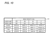
- FIG. 10 shows an example of the recording medium laser absorption index conversion table.
- the recording medium laser absorption index conversion table 141 is a table for setting a laser absorption index of each pixel in the recording medium image block from a combination of a color of the printing part and a density of the printing part.
- a color of the printing part is black (K)
- K black
- “3” is set as the laser absorption index
- “2” is set as the laser absorption index
- “1” is set as the laser absorption index
- “0” is set as the laser absorption index.
- the laser absorption indexes of “0” or larger and “2” or smaller are set by the pixel density, as shown in FIG. 10 .
- the recording medium laser absorption index conversion table 141 may be set so that even when the densities of the printing parts are the same high density, the laser absorption indexes become different by colors of the printing part.
- the reason is as follows: the printing part of black (K) can absorb the laser more easily than cyan (C) and magenta (M) and the printing part of yellow (Y) is more difficult to absorb the laser than cyan (C) and magenta (M), so that the corresponding properties are reflected in the recording medium laser absorption index conversion table 141 .
- the recording medium laser absorption index conversion table 141 shown in FIG. 10 is just exemplary and the setting values indicating the laser absorption indexes may be changed depending on an amount of the IR absorption agent included in each color of YMCK, for example. Also, the density of an image may be classified into any number of classifications other than the above four types of the high density, the middle density, the low density and the non-density.
- the humidity may be measured by a humidity sensor (not shown) and the setting values indicating the laser absorption indexes may be changed depending on the humidity.
- FIG. 11 illustrates an example of recording medium laser absorption index data that is generated from the recording medium image block information 131 by referring to the recording medium laser absorption index conversion table 141 shown in FIG. 10 .
- laser absorption index data 142 “3” is set as the laser absorption index of each pixel in the high density printing area 132 , “2” is set as the laser absorption index of each pixel in the middle density printing area 134 , “1” is set as the laser absorption index of each pixel in the low density printing area 136 and “0” is set as the laser absorption index of each pixel in the non-printing area 138 .
- step S 30 the control unit 20 generates laser illumination intensity data by using the user image block information 111 acquired in the processing of step S 10 by referring to a laser illumination intensity conversion table beforehand stored in the storage unit 30 .
- FIG. 12 shows an example of the laser illumination intensity conversion table.
- the laser illumination intensity conversion table 150 is a table for setting a laser illumination intensity to be illuminated from the VCSEL 72 to each pixel in the user image block, on the basis of the combination of the color of ink droplet and the droplet amount of ink droplet.
- a color of the ink droplet is black (K)
- 3 [J/cm 2 ] is set as the laser illumination intensity of the VCSEL 72
- 2 [J/cm 2 ] is set as the laser illumination intensity of the VCSEL 72
- 1 [J/cm 2 ] is set as the laser illumination intensity of the VCSEL 72
- 0 [J/cm 2 ] is set as the laser illumination intensity of the VCSEL 72 .
- the same values as black (K) are set by the droplet amounts of ink droplet.
- the laser illumination intensity conversion table 150 shown in FIG. 12 is exemplary and the setting values indicating the laser illumination intensities may be changed depending on an amount of the IR absorption agent included in each color of YMCK, for example.
- the droplet amount of ink droplet may be classified into three types, five types and the like different from the above four types of the large droplet, the middle droplet, the small droplet and no ink droplet.
- FIG. 13 illustrates an example of laser illumination intensity data that is generated from the user image block information 111 by referring to the laser illumination intensity conversion table 150 shown in FIG. 12 .
- the laser illumination intensity data 152 “3” is set as the laser illumination intensity of each pixel in the large droplet image area 112 , “2” is set as the laser illumination intensity of each pixel in the middle droplet image area 114 , “1” is set as the laser illumination intensity of each pixel in the small droplet image area 116 and “0” is set as the laser illumination intensity of each pixel for which it is not necessary to eject the ink droplet.
- the setting value for each pixel in the laser illumination intensity data 152 set as described above indicates the laser illumination intensity of each VCSEL 72 configured to illuminate each pixel.
- step S 40 the control unit 20 generates a laser illumination intensity correction coefficient table for correcting the laser illumination intensity data 152 so that the laser illumination intensity to a pixel, in which a printing part having the low density or higher and a user image for which an ink droplet having a droplet amount of the small droplet or larger is ejected overlap with each other, becomes lower than the laser illumination intensity set in the laser illumination intensity data 152 generated in the processing of step S 30 .
- the pixel corresponding to a position at which a printing part having the low density or higher and a user image for which an ink droplet having a droplet amount of the small droplet or larger is ejected overlap with each other is referred to as an overlapping pixel.
- any calculation equation may be used inasmuch as the laser illumination intensity to the overlapping pixel is corrected to a value smaller than the setting value of the laser illumination intensity data 152 corresponding to the overlapping pixel.
- control unit 20 is configured to calculate a laser illumination intensity correction coefficient Ci for each pixel i in the laser illumination intensity correction coefficient table by using an equation (1).
- Ci Ai /( Ai+Bi ) (1)
- i indicates a suffix for identifying each pixel included in the user image block
- Ai indicates a setting value of the user image laser absorption index data 121 corresponding to a pixel i
- Bi indicates a setting value of the recording medium laser absorption index data 142 corresponding to a pixel i.
- FIG. 14 illustrates an example of the laser illumination intensity correction coefficient table that is generated by assigning respective setting values of the user image laser absorption index data 121 and the recording medium laser absorption index data 142 for a pixel i to the equation (1).
- the laser illumination intensity correction coefficient table 154 shown in FIG. 14 shows the laser illumination intensity correction coefficients of an area corresponding to an area 153 A in FIG. 13 , which are selected from the laser illumination intensity correction coefficient table generated from the user image laser absorption index data 121 and the recording medium laser absorption index data 142 , for convenience of explanations.
- the laser illumination intensity correction coefficient table 154 is a table including the laser illumination intensity correction coefficients of 60 pixels ⁇ 60 pixels.
- the laser illumination intensity correction coefficient of an overlapping pixel is smaller than 1 in the laser illumination intensity correction coefficient table 154 .
- the laser illumination intensity correction coefficient table 154 is generated.
- step S 50 the control unit 20 corrects the laser illumination intensity data 152 generated in step S 30 by using the laser illumination intensity correction coefficient table 154 generated in step S 40 .
- control unit 20 corrects the laser illumination intensity data 152 by multiplying the laser illumination intensity of the laser illumination intensity data 152 and the laser illumination intensity correction coefficient of the laser illumination intensity correction coefficient table 154 for each pixel.
- FIG. 15 illustrates an example of corrected laser illumination intensity data.
- corrected laser illumination intensity data 152 A which is the corrected laser illumination intensity data
- the laser illumination intensity corresponding to the overlapping pixel becomes lower than the laser illumination intensity of the laser illumination intensity data 152 corresponding to the same overlapping pixel.
- the laser illumination intensity is reduced from 3 [J/cm 2 ] to 1.5 [J/cm 2 ], and in an area 162 including the overlapping pixels of the middle droplet image area 114 and the high density printing area 132 , the laser illumination intensity is reduced from 2 [J/cm 2 ] to 0.8 [J/cm 2 ]. Also, in an area 164 including the overlapping pixels of the small droplet image area 116 and the high density printing area 132 , the laser illumination intensity is reduced from 1 [J/cm 2 ] to 0.3 [J/cm 2 ]. Likewise, the laser illumination intensity in an area including the other overlapping pixels is also reduced, as compared to the laser illumination intensity of the laser illumination intensity data 152 .
- step S 60 the control unit 20 controls the head driving unit 40 to eject the ink droplets of the designated colors from the printing head 50 to the ejection positions of the continuous sheet P, which are designated with the user image block information 111 acquired from the storage unit 30 in the processing of step S 10 , by the designated amounts.
- step S 70 the control unit 20 controls the laser driving unit 64 ) so that the laser is illuminated from the VCSELs 72 to the ink droplets at timings at which the respective ink droplets on the continuous sheet P are conveyed into the laser illumination ranges of the corresponding VCSELs 72 .
- the laser illumination intensity of the VCSEL 72 configured to illuminate the laser to the ink droplet of the overlapping pixel is reduced, as compared to the laser illumination intensity set by the laser illumination intensity data 152 , and then the laser is illuminated from the VCSEL 72 .
- the printing resolution of the printing head 50 is 600 dpi in both the sheet conveying direction and the sheet width direction and the light emitting resolution of the laser drying device 70 is also 600 dpi in both the sheet conveying direction and the sheet width direction. That is, in the inkjet recording apparatus 10 of the first illustrative embodiment, the laser illumination range of the VCSEL 72 and the ink droplet correspond to each other one to one.
- the printing resolution of the printing head is 600 dpi in both the sheet conveying direction and the sheet width direction but the light emitting resolution of the laser drying device is set to be lower than the printing resolution.
- the light emitting resolution of the laser drying device of the second illustrative embodiment is 20 dpi in both the sheet conveying direction and the sheet width direction. That is, as shown in FIG. 16 , 30 ink droplets PX are included in a laser illumination range R on the continuous sheet P illuminated by one VCSEL in both the sheet conveying direction and the sheet width direction, respectively.
- the main constitutional parts of the inkjet recording apparatus 10 according to the second illustrative embodiment are the same as FIG. 1 , except that the light emitting resolution of the laser drying device is different from the light emitting resolution of the laser drying device 70 according to the first illustrative embodiment. Therefore, the main configuration of the electric system of the inkjet recording apparatus 10 according to the second illustrative embodiment is also the same as FIG. 4 .
- the laser drying device of the second illustrative embodiment is referred to as a laser drying device 70 ′, and the VCSEL is referred to as a VCSEL 72 ′.
- FIG. 17 is a flowchart showing an example of processing of a drying program according to the second illustrative embodiment, which is executed by the CPU 201 of the computer 20 when the user image information is received from the user.
- FIG. 17 The flowchart shown in FIG. 17 is different from FIG. 5 showing an example of the flowchart of the drying processing according to the first illustrative embodiment, in that steps S 35 and S 45 are added and the processing of step S 50 is replaced with step S 55 . Therefore, the processing of steps S 35 , S 45 and S 55 is focused in the below descriptions.
- step S 35 the control unit 20 corrects the laser illumination intensity data 152 generated in the processing of step S 30 , in conformity to the light emitting resolution of the laser drying device 70 ′.
- the control unit 20 divides the laser illumination intensity data 152 for each laser illumination range R.
- FIG. 18 illustrates an example of a relation between the laser illumination intensity data 152 for each pixel generated in the processing of step S 30 and the laser illumination range R of the VCSEL 72 ′.
- the laser illumination intensity data 152 is divided into four areas 153 A, 153 B, 153 C, 153 D. Each of the areas 153 A to 153 D indicates the laser illumination range R of the VCSEL 72 ′.
- the control unit 20 should set the laser illumination intensity data for each range of the areas 153 A to 153 D.
- control unit 20 sets the laser illumination intensity data for each of the areas 153 A to 153 D by using the laser illumination intensity data 152 set for each pixel included in the respective areas 153 A to 153 D.
- the control unit 20 sets the lowest laser illumination intensity of the laser illumination intensity data 152 included in each area, as the laser illumination intensity for the corresponding area, for each of the areas 153 A to 153 D.
- the lowest laser illumination intensity means the lowest laser illumination intensity of the laser illumination intensities of the laser illumination intensity data 152 corresponding to the ejection positions of the respective ink droplets on the continuous sheet P, in an area including at least one or more ink droplets.
- the laser illumination intensity is 0 [J/cm 2 ].
- the laser illumination intensity of the areas 153 A. 153 B is set to be 1 [J/cm 2 ] and the laser illumination intensity of the areas 153 C, 153 D is set to be 0 [J/cm 2 ].
- the reason to set, as the laser illumination intensity of each of the areas 153 A to 153 D, the lowest laser illumination intensity of the laser illumination intensities set in the laser illumination intensity data 152 in the corresponding area is so as not to illuminate the laser exceeding the illumination intensity necessary for the drying, which is set in the laser illumination intensity data 152 , to the ink droplets included in each of the areas 153 A to 153 D.
- the method of setting the laser illumination intensity in each of the areas 153 A to 153 D is not limited to the above described method.
- the laser illumination intensity in each of the areas 153 A to 153 D may be set by a weighted average of the laser illumination intensity in each area.
- the weighted average of the laser illumination intensity in each area means a value that is obtained by dividing a sum of the laser illumination intensities of the respective pixels included in an area by the number of pixels included in the area, in the laser illumination intensity data 152 .
- the laser illumination intensity is set in conformity to a distribution situation of the laser illumination intensities set for respective pixels in the area. For example, in case that the laser illumination intensity of 1 [J/cm 2 ] is set for one pixel and the laser illumination intensity of 3 [J/cm 2 ] is set for the other pixels in the area 153 A, when the laser illumination intensity of the area 153 A is set by the weighted average, not 1 [J/cm 2 ], the deterioration of the image quality of the user image may be overall suppressed in some cases.
- step S 45 the control unit 20 corrects the laser illumination intensity correction coefficient table 154 generated in the processing of step S 40 , in conformity to the light emitting resolution of the laser drying device 70 ′.
- the control unit 20 divides the laser illumination intensity correction coefficient table 154 into the same four areas as the areas 153 A to 153 D shown in FIG. 18 . Then, the control unit 20 sets, as the laser illumination intensity correction coefficient of the area 153 A, the smallest laser illumination intensity correction coefficient of the laser illumination intensity correction coefficient table 154 (refer to FIG. 14 ) corresponding to the area 153 A, and corrects the laser illumination intensity correction coefficient table 154 generated in step S 40 . Further, the control unit 20 sets the laser illumination intensity correction coefficients of the areas 153 B to 153 D in the same manner.
- the smallest laser illumination intensity correction coefficient of each of the areas 153 B to 153 D means the smallest laser illumination intensity correction coefficient of the laser illumination intensity correction coefficients corresponding to the ejection positions of the respective ink droplets on the continuous sheet P, in an area including at least one or more ink droplets. In an area not including the ink droplet, the smallest laser illumination intensity correction coefficient is 0.
- FIG. 19 illustrates an example of the laser illumination intensity correction coefficient table 154 corrected in the processing of step S 45 .
- the laser illumination intensity correction coefficient of the area 153 A is set to 0.3
- the laser illumination intensity correction coefficient of the area 153 B is set to 1
- the laser illumination intensity correction coefficients of the areas 153 C, 153 D are set to 0.
- step S 55 the control unit 20 corrects the laser illumination intensity data 152 corrected in step S 35 by using the laser illumination intensity correction coefficient table 154 corrected in step S 45 .
- the method of correcting the corrected laser illumination intensity data 152 is the same as the processing of step S 50 in the first illustrative embodiment. That is, the control unit 20 corrects the corrected laser illumination intensity data 152 by multiplying the laser illumination intensity of the laser illumination intensity data 152 corrected in step S 35 and the laser illumination intensity correction coefficient of the laser illumination intensity correction coefficient table 154 corrected in step S 45 , for each pixel.
- the illumination intensity of the VCSEL 72 ′ illuminating the area 153 A is set to 0.3 [J/cm 2 ] by the multiplication thereof.
- the illumination intensity of the VCSEL 72 ′ illuminating the area 153 B is set to 1 [J/cm 2 ] and the illumination intensity of the VCSEL 72 ′ illuminating the areas 153 C, 153 D is set to 0 [J/cm 2 ].
- the laser illumination intensity and laser illumination intensity correction coefficient of the VCSEL 72 ′ corresponding to the laser illumination range R are set to the smallest values of the laser illumination intensities and laser illumination intensity correction coefficients set for the respective pixels included in the laser illumination range R. Therefore, as compared to a configuration where the smallest values of the laser illumination intensities and laser illumination intensity correction coefficients set for the respective pixels included in the laser illumination range R are not selected, the laser illumination intensity to be illuminated to the printing part is suppressed to be low, so that the discoloring of the printing part is suppressed.
- the control unit 20 may be configured to stop the laser illumination from the VCSEL 72 ′ configured to illuminate the corresponding area.
- the control unit 20 may be configured to set the laser illumination intensity in the area 153 A from 1 [J/cm 2 ] to 0 [J/cm 2 ].
- the control unit 20 controls the laser driving unit 60 so that the laser is illuminated to the area 153 B with the value set by the laser illumination intensity data 152 corrected in the processing of step S 55 , i.e., 1 [J/cm 2 ]. Also, since the user image is not included in the area 153 C and the area 153 D, the control unit 20 controls the laser driving unit 60 so that the laser is not illuminated to the area 153 C and the area 153 D.
- the drying processing is implemented by the software configuration.
- the present invention is not limited thereto.
- the drying processing may also be implemented by a hardware configuration.
- a functional device configured to execute the same processing as the control unit 20 may be prepared and used. In this case, it is expected to execute the processing at higher speed, as compared to the above illustrative embodiments.
- the continuous sheet P is used as the recording medium.
- the type of the recording medium is not limited thereto.
- a cut sheet such as A 4 and A 3 may also be used.
- the material of the recording medium is not limited to the sheet.
- any material to which the ink droplets are fixed by the laser illumination may also be used.
- the type of the laser in the above illustrative embodiments is not particularly limited.
- a VCSEL configured to illuminate UV (Ultra Violet) laser having a wavelength in an ultraviolet region may also be used, in addition to the VCSEL configured to illuminate the infrared laser having a wavelength in an infrared region.
Landscapes
- Health & Medical Sciences (AREA)
- General Health & Medical Sciences (AREA)
- Toxicology (AREA)
- Ink Jet (AREA)
Abstract
Description
Ci=Ai/(Ai+Bi) (1)
Claims (7)
Applications Claiming Priority (2)
| Application Number | Priority Date | Filing Date | Title |
|---|---|---|---|
| JP2014-194363 | 2014-09-24 | ||
| JP2014194363A JP6413550B2 (en) | 2014-09-24 | 2014-09-24 | Drying apparatus, drying program, and image forming apparatus |
Publications (2)
| Publication Number | Publication Date |
|---|---|
| US20160082748A1 US20160082748A1 (en) | 2016-03-24 |
| US9505237B2 true US9505237B2 (en) | 2016-11-29 |
Family
ID=55524953
Family Applications (1)
| Application Number | Title | Priority Date | Filing Date |
|---|---|---|---|
| US14/609,477 Active US9505237B2 (en) | 2014-09-24 | 2015-01-30 | Drying device and image forming apparatus |
Country Status (2)
| Country | Link |
|---|---|
| US (1) | US9505237B2 (en) |
| JP (1) | JP6413550B2 (en) |
Families Citing this family (1)
| Publication number | Priority date | Publication date | Assignee | Title |
|---|---|---|---|---|
| JP2018001556A (en) | 2016-06-30 | 2018-01-11 | 富士ゼロックス株式会社 | Drying device, drying program, and image formation device |
Citations (7)
| Publication number | Priority date | Publication date | Assignee | Title |
|---|---|---|---|---|
| US20050012778A1 (en) * | 2003-07-15 | 2005-01-20 | Konica Minolta Medical & Graphic, Inc. | Inkjet printer using ultraviolet cure ink |
| US20060050122A1 (en) * | 2004-07-21 | 2006-03-09 | Seiko Epson Corporation | Ultraviolet rays emitter |
| US20060209150A1 (en) * | 2005-03-18 | 2006-09-21 | Seiko Epson Corporation | Liquid ejection apparatus |
| US20090033696A1 (en) * | 2007-08-02 | 2009-02-05 | Seiko Epson Corporation | Pattern forming method and droplet discharge device |
| US20090225143A1 (en) * | 2008-03-04 | 2009-09-10 | Takashi Fukui | Image forming apparatus and method |
| US20100073410A1 (en) * | 2008-09-24 | 2010-03-25 | Fuji Xerox Co., Ltd. | Recording apparatus and recording method |
| JP2013256260A (en) | 2012-06-14 | 2013-12-26 | Suzuki Motor Corp | Torsion beam structure of torsion beam type suspension |
Family Cites Families (1)
| Publication number | Priority date | Publication date | Assignee | Title |
|---|---|---|---|---|
| US9446602B2 (en) * | 2012-07-26 | 2016-09-20 | Ceraloc Innovation Ab | Digital binder printing |
-
2014
- 2014-09-24 JP JP2014194363A patent/JP6413550B2/en not_active Expired - Fee Related
-
2015
- 2015-01-30 US US14/609,477 patent/US9505237B2/en active Active
Patent Citations (7)
| Publication number | Priority date | Publication date | Assignee | Title |
|---|---|---|---|---|
| US20050012778A1 (en) * | 2003-07-15 | 2005-01-20 | Konica Minolta Medical & Graphic, Inc. | Inkjet printer using ultraviolet cure ink |
| US20060050122A1 (en) * | 2004-07-21 | 2006-03-09 | Seiko Epson Corporation | Ultraviolet rays emitter |
| US20060209150A1 (en) * | 2005-03-18 | 2006-09-21 | Seiko Epson Corporation | Liquid ejection apparatus |
| US20090033696A1 (en) * | 2007-08-02 | 2009-02-05 | Seiko Epson Corporation | Pattern forming method and droplet discharge device |
| US20090225143A1 (en) * | 2008-03-04 | 2009-09-10 | Takashi Fukui | Image forming apparatus and method |
| US20100073410A1 (en) * | 2008-09-24 | 2010-03-25 | Fuji Xerox Co., Ltd. | Recording apparatus and recording method |
| JP2013256260A (en) | 2012-06-14 | 2013-12-26 | Suzuki Motor Corp | Torsion beam structure of torsion beam type suspension |
Non-Patent Citations (1)
| Title |
|---|
| Abstract and machine translation of JP 2013-256260. |
Also Published As
| Publication number | Publication date |
|---|---|
| JP6413550B2 (en) | 2018-10-31 |
| JP2016064565A (en) | 2016-04-28 |
| US20160082748A1 (en) | 2016-03-24 |
Similar Documents
| Publication | Publication Date | Title |
|---|---|---|
| US8851618B2 (en) | Inkjet printing apparatus and inkjet printing method | |
| JP4992788B2 (en) | Correction value calculation method and liquid ejection method | |
| US9393790B2 (en) | Inkjet print apparatus and inkjet printing method | |
| JP6180146B2 (en) | Color measuring device, recording device, and color measuring method | |
| US8186801B2 (en) | Image forming device | |
| US9462147B2 (en) | Image processing apparatus, image processing method, recording apparatus, and non-transitory computer-readable storage medium | |
| CN107225863A (en) | Liquid sprays control device, liquid and sprays control method, liquid ejection control program | |
| JP6135045B2 (en) | Printing apparatus, correction value acquisition method, and printing apparatus manufacturing method | |
| US11999177B2 (en) | Printing apparatus, printing method, and storage medium | |
| US20210138796A1 (en) | Multifunction peripheral, control method thereof, and storage medium storing program | |
| US9505237B2 (en) | Drying device and image forming apparatus | |
| US20110193905A1 (en) | Printing device | |
| US9889649B2 (en) | Printing control device, printing control method, and storage medium | |
| JP2012198177A (en) | Print control device, printer, print control method, and print control program | |
| US20200238726A1 (en) | Image forming apparatus | |
| US20250001768A1 (en) | Image forming apparatus | |
| US9742961B2 (en) | To calibrate a printer | |
| US11951752B2 (en) | Controller, printer, and computer-readable storage medium | |
| US11017277B2 (en) | Image processing apparatus, image processing method and storage medium, with correction amount for correcting line width in accordance with color of line | |
| JP2017148943A (en) | Print control apparatus, print control method, and computer program therefor | |
| US11960948B2 (en) | Printing device performing halftone process to convert image data according to target conversion method | |
| JP7419774B2 (en) | Printing device production method and printing device | |
| US20260004097A1 (en) | Liquid droplet ejecting apparatus, liquid droplet ejecting method, and medium storing program for liquid droplet ejecting apparatus | |
| US11491784B2 (en) | Image forming apparatus | |
| US20210144262A1 (en) | Image processing apparatus, image processing system, and control method of image processing apparatus |
Legal Events
| Date | Code | Title | Description |
|---|---|---|---|
| AS | Assignment |
Owner name: FUJI XEROX CO., LTD., JAPAN Free format text: ASSIGNMENT OF ASSIGNORS INTEREST;ASSIGNORS:ZENGO, TAKESHI;SAKAMOTO, AKIRA;MORITA, NAOKI;AND OTHERS;REEL/FRAME:034849/0867 Effective date: 20150129 |
|
| STCF | Information on status: patent grant |
Free format text: PATENTED CASE |
|
| MAFP | Maintenance fee payment |
Free format text: PAYMENT OF MAINTENANCE FEE, 4TH YEAR, LARGE ENTITY (ORIGINAL EVENT CODE: M1551); ENTITY STATUS OF PATENT OWNER: LARGE ENTITY Year of fee payment: 4 |
|
| AS | Assignment |
Owner name: FUJIFILM BUSINESS INNOVATION CORP., JAPAN Free format text: CHANGE OF NAME;ASSIGNOR:FUJI XEROX CO., LTD.;REEL/FRAME:058287/0056 Effective date: 20210401 |
|
| MAFP | Maintenance fee payment |
Free format text: PAYMENT OF MAINTENANCE FEE, 8TH YEAR, LARGE ENTITY (ORIGINAL EVENT CODE: M1552); ENTITY STATUS OF PATENT OWNER: LARGE ENTITY Year of fee payment: 8 |