US9501452B2 - Exponentially weighted moving averaging filter with adjustable weighting factor - Google Patents
Exponentially weighted moving averaging filter with adjustable weighting factor Download PDFInfo
- Publication number
- US9501452B2 US9501452B2 US14/055,092 US201314055092A US9501452B2 US 9501452 B2 US9501452 B2 US 9501452B2 US 201314055092 A US201314055092 A US 201314055092A US 9501452 B2 US9501452 B2 US 9501452B2
- Authority
- US
- United States
- Prior art keywords
- ewma
- value
- wpa
- filter
- module
- Prior art date
- Legal status (The legal status is an assumption and is not a legal conclusion. Google has not performed a legal analysis and makes no representation as to the accuracy of the status listed.)
- Active, expires
Links
- 238000012935 Averaging Methods 0.000 title claims abstract description 9
- 238000000034 method Methods 0.000 claims abstract description 17
- 238000012544 monitoring process Methods 0.000 claims abstract description 4
- 230000035876 healing Effects 0.000 claims description 13
- 230000009471 action Effects 0.000 claims description 8
- 238000002405 diagnostic procedure Methods 0.000 description 24
- 238000005086 pumping Methods 0.000 description 17
- 238000012360 testing method Methods 0.000 description 13
- 239000007789 gas Substances 0.000 description 8
- MWUXSHHQAYIFBG-UHFFFAOYSA-N Nitric oxide Chemical compound O=[N] MWUXSHHQAYIFBG-UHFFFAOYSA-N 0.000 description 6
- 238000001914 filtration Methods 0.000 description 6
- 238000013459 approach Methods 0.000 description 3
- 238000010586 diagram Methods 0.000 description 3
- 238000002485 combustion reaction Methods 0.000 description 2
- 238000011109 contamination Methods 0.000 description 2
- 230000007257 malfunction Effects 0.000 description 2
- QVGXLLKOCUKJST-UHFFFAOYSA-N atomic oxygen Chemical compound [O] QVGXLLKOCUKJST-UHFFFAOYSA-N 0.000 description 1
- 239000003054 catalyst Substances 0.000 description 1
- 238000010531 catalytic reduction reaction Methods 0.000 description 1
- 230000008859 change Effects 0.000 description 1
- 238000004891 communication Methods 0.000 description 1
- 239000000463 material Substances 0.000 description 1
- 238000012986 modification Methods 0.000 description 1
- 230000004048 modification Effects 0.000 description 1
- 239000001301 oxygen Substances 0.000 description 1
- 229910052760 oxygen Inorganic materials 0.000 description 1
- 238000012545 processing Methods 0.000 description 1
- 230000008439 repair process Effects 0.000 description 1
Images


Classifications
-
- G—PHYSICS
- G06—COMPUTING; CALCULATING OR COUNTING
- G06F—ELECTRIC DIGITAL DATA PROCESSING
- G06F17/00—Digital computing or data processing equipment or methods, specially adapted for specific functions
- G06F17/10—Complex mathematical operations
- G06F17/18—Complex mathematical operations for evaluating statistical data, e.g. average values, frequency distributions, probability functions, regression analysis
-
- F—MECHANICAL ENGINEERING; LIGHTING; HEATING; WEAPONS; BLASTING
- F01—MACHINES OR ENGINES IN GENERAL; ENGINE PLANTS IN GENERAL; STEAM ENGINES
- F01N—GAS-FLOW SILENCERS OR EXHAUST APPARATUS FOR MACHINES OR ENGINES IN GENERAL; GAS-FLOW SILENCERS OR EXHAUST APPARATUS FOR INTERNAL COMBUSTION ENGINES
- F01N11/00—Monitoring or diagnostic devices for exhaust-gas treatment apparatus, e.g. for catalytic activity
-
- F—MECHANICAL ENGINEERING; LIGHTING; HEATING; WEAPONS; BLASTING
- F02—COMBUSTION ENGINES; HOT-GAS OR COMBUSTION-PRODUCT ENGINE PLANTS
- F02D—CONTROLLING COMBUSTION ENGINES
- F02D41/00—Electrical control of supply of combustible mixture or its constituents
- F02D41/22—Safety or indicating devices for abnormal conditions
- F02D41/222—Safety or indicating devices for abnormal conditions relating to the failure of sensors or parameter detection devices
-
- F—MECHANICAL ENGINEERING; LIGHTING; HEATING; WEAPONS; BLASTING
- F01—MACHINES OR ENGINES IN GENERAL; ENGINE PLANTS IN GENERAL; STEAM ENGINES
- F01N—GAS-FLOW SILENCERS OR EXHAUST APPARATUS FOR MACHINES OR ENGINES IN GENERAL; GAS-FLOW SILENCERS OR EXHAUST APPARATUS FOR INTERNAL COMBUSTION ENGINES
- F01N2560/00—Exhaust systems with means for detecting or measuring exhaust gas components or characteristics
- F01N2560/02—Exhaust systems with means for detecting or measuring exhaust gas components or characteristics the means being an exhaust gas sensor
- F01N2560/026—Exhaust systems with means for detecting or measuring exhaust gas components or characteristics the means being an exhaust gas sensor for measuring or detecting NOx
-
- F—MECHANICAL ENGINEERING; LIGHTING; HEATING; WEAPONS; BLASTING
- F02—COMBUSTION ENGINES; HOT-GAS OR COMBUSTION-PRODUCT ENGINE PLANTS
- F02D—CONTROLLING COMBUSTION ENGINES
- F02D41/00—Electrical control of supply of combustible mixture or its constituents
- F02D41/02—Circuit arrangements for generating control signals
- F02D41/14—Introducing closed-loop corrections
- F02D41/1401—Introducing closed-loop corrections characterised by the control or regulation method
- F02D2041/1413—Controller structures or design
- F02D2041/1432—Controller structures or design the system including a filter, e.g. a low pass or high pass filter
-
- F—MECHANICAL ENGINEERING; LIGHTING; HEATING; WEAPONS; BLASTING
- F02—COMBUSTION ENGINES; HOT-GAS OR COMBUSTION-PRODUCT ENGINE PLANTS
- F02D—CONTROLLING COMBUSTION ENGINES
- F02D41/00—Electrical control of supply of combustible mixture or its constituents
- F02D41/02—Circuit arrangements for generating control signals
- F02D41/14—Introducing closed-loop corrections
- F02D41/1438—Introducing closed-loop corrections using means for determining characteristics of the combustion gases; Sensors therefor
- F02D41/1444—Introducing closed-loop corrections using means for determining characteristics of the combustion gases; Sensors therefor characterised by the characteristics of the combustion gases
- F02D41/146—Introducing closed-loop corrections using means for determining characteristics of the combustion gases; Sensors therefor characterised by the characteristics of the combustion gases the characteristics being an NOx content or concentration
-
- Y—GENERAL TAGGING OF NEW TECHNOLOGICAL DEVELOPMENTS; GENERAL TAGGING OF CROSS-SECTIONAL TECHNOLOGIES SPANNING OVER SEVERAL SECTIONS OF THE IPC; TECHNICAL SUBJECTS COVERED BY FORMER USPC CROSS-REFERENCE ART COLLECTIONS [XRACs] AND DIGESTS
- Y02—TECHNOLOGIES OR APPLICATIONS FOR MITIGATION OR ADAPTATION AGAINST CLIMATE CHANGE
- Y02T—CLIMATE CHANGE MITIGATION TECHNOLOGIES RELATED TO TRANSPORTATION
- Y02T10/00—Road transport of goods or passengers
- Y02T10/10—Internal combustion engine [ICE] based vehicles
- Y02T10/40—Engine management systems
-
- Y02T10/47—
Definitions
- Exemplary embodiments of the invention relate to a system and method of increasing a weighting factor of an Exponentially Weighted Moving Averaging (“EWMA”) filter and, more particularly, to a system and method of increasing a weighting factor to more heavily weigh incoming raw data values of a data stream.
- EWMA Exponentially Weighted Moving Averaging
- Exponentially Weighted Moving Averaging (“EWMA”) filtering is a data processing technique used to reduce the variability of an incoming stream of data that is monitored over a period of time.
- a EWMA filter calculates an averaged or filtered value that is based on raw data points collected from the incoming stream of data.
- EWMA filtering may be used to filter data collected by a nitrogen oxide sensor (“NOx”) sensor.
- NOx nitrogen oxide sensor
- the NOx sensor may be located within an exhaust gas conduit of an exhaust gas treatment system, and is used to generate a signal that is indicative of the level of NOx in exhaust gas emitted from an internal combustion engine.
- the EWMA filter monitors the data collected by the NOx sensor to determine a filtered value.
- a diagnostic trouble code (“DTC”) may be set to a fail status.
- the fail status indicates that there may be an issue with the NOx sensor (e.g., an element in the sensor is cracked, or contaminated), and a malfunction indicator light (“MIL”) may be illuminated to indicate the fault. Corrective action may be taken to repair or replace the NOx sensor.
- the MIL light will eventually be turned off or deactivated after the filtered value determined by the EWMA filter is below the fault threshold value, and the diagnostic test is passed a predetermined number of times.
- some types of regulations require that the diagnostic test passes for three key or ignition cycles before the MIL is allowed to deactivate at the beginning of the fourth key cycle.
- EWMA filtering may delay deactivating the MIL. This is because EWMA filtering tends to place significant emphasis on relatively older data collected from the NOx sensor that indicates the fail status. Thus, the filtered value calculated by the EWMA filter may exceed the threshold value even after the NOx sensor has been repaired or replaced. Accordingly, it is desirable to provide an approach for EWMA filtering that provides a filtered value with increased accuracy.
- a method of increasing a weighting factor of an exponentially weighted moving averaging (“EWMA”) filter includes monitoring a data stream containing raw data values, and determining an EWMA value based on the data stream by an electronic control module. The method includes determining if the EWMA value is between a predetermined maximum fault threshold value and a predetermined minimum fault threshold value. The method includes increasing the weighting factor of the EWMA filter to more heavily weigh incoming raw data values of the data stream based on the difference between the first raw data value and a previously calculated filtered value exceeding the calibration value. In one embodiment, the weighting factor is determined empirically.
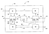
- FIG. 1 is an exemplary schematic diagram of a diagnostic system including a sensor and a control module
- FIG. 2 is a graph illustrating raw values collected by the sensor in FIG. 1 and averaged or filtered values calculated by an EWMA filter;
- FIG. 3 is a dataflow diagram of the control module shown in FIG. 1 .
- module refers to an application specific integrated circuit (ASIC), an electronic circuit, a processor (shared, dedicated, or group) and memory that executes one or more software or firmware programs, or a combinational logic circuit.
- ASIC application specific integrated circuit
- processor shared, dedicated, or group
- memory that executes one or more software or firmware programs, or a combinational logic circuit.
- an exemplary embodiment is directed to a diagnostic system 10 for an exhaust gas treatment system 12 including an exhaust gas conduit 20 , a nitrogen oxide (“NOx”) sensor 22 , a malfunction indicator lamp (“MIL”) 26 and a control module 30 .
- the control module 30 is in communication with the NOx sensor 22 and the MIL 26 .
- the NOx sensor 20 monitors an exhaust gas 32 produced by an internal combustion engine (not shown), and generates a signal indicative of a level of NOx in the exhaust gas 32 .
- the control module 30 monitors the NOx sensor 22 to determine the level of NOx in the exhaust gas 32 .
- the control module 30 uses an exponentially weighted moving averaging (“EWMA”) filter 36 to reduce the variability of a stream of data that is collected over a period of time by the NOx sensor 22 .
- EWMA exponentially weighted moving averaging
- FIG. 1 illustrates the control module 30 monitoring a NOx sensor 22
- the diagnostic system 10 may be applied to any type of diagnostic system that uses EWMA filtering to reduce the variability of raw data that is collected over a period of time.
- the diagnostic system 10 may be used to filter catalyst test data from a device such as, for example, a selective catalytic reduction (“SCR”) device.
- SCR selective catalytic reduction
- Some other examples of the diagnostic system 10 may include an air quality system.
- the NOx sensor 22 generates a pumping current ratio signal to indicate whether the NOx sensor 22 is functioning as intended.
- the pumping current ratio is based on the amount of current needed to pump 1000 ppm of oxygen (“O 2 ”) into a chamber (not shown) of the NOx sensor 22 , and indicates if the NOx sensor 22 has faulted. For example, if the pumping current ratio is relatively high, this may indicate contamination of the NOx sensor 22 , and if the pumping current ratio is relatively low, this may indicate a cracked NOx sensor 22 .
- the EWMA filter 36 receives, as input, the pumping current ratio signal from the NOx sensor 22 .
- the pumping current ratio signal is a raw data value collected by the NOx sensor 22 over a period of time.
- the EWMA filter 36 determines averaged or filtered pumping current ratio values based on the raw data.
- FIG. 2 is an exemplary graph illustrating a stream of raw values 40 (e.g., the pumping current ratio (PCR) signal) collected over a period of time t by the NOx sensor 22 ( FIG. 1 ).
- Each raw value 40 represents the results of a diagnostic test (e.g., each raw value 40 represents the results of one diagnostic test, and the graph in FIG. 2 is an illustration of twelve different diagnostic tests).
- the control module 30 FIG. 1 ) performs a self-diagnostic test by determining if the pumping current ratio signal generated by the NOx sensor 22 indicates a fault within the NOx sensor 22 .
- the EWMA filter 36 ( FIG. 1 ) determines averaged or filtered values 42 based on the raw values 40 .
- the graph also illustrates a maximum fault threshold value 50 , a maximum re-pass threshold 52 , a worst performing acceptable (“WPA”) maximum level 54 , a WPA nominal level 56 , a WPA minimum level 58 , a minimum re-pass value 57 , and a minimum fault threshold value 59 .
- WPA worst performing acceptable
- the maximum fault threshold value 50 represents the minimum pumping current ratio value required to trigger a fault in the control module 30 indicating a fault due to an elevated pumping current ratio such as, for example, contamination of the NOx sensor 22 .
- a diagnostic trouble code (“DTC”) may be set to a fail status by the control module 30 .
- the failed status indicates that a fault within the NOx sensor 22 may have occurred, and therefore the MIL 26 may be illuminated by the control module 30 .
- the maximum re-pass value 52 represents the filtered value 42 that the EWMA filter 36 is required to generate before the control module 30 may reset the DTC to a pass status after the filtered value 42 has exceeded the maximum fault threshold value 50 and the fail status has been set.
- the WPA maximum level 54 , the WPA nominal level 56 , and the WPA minimum level 58 represent a range of acceptable raw values 40 that may be used by control module 30 during a diagnostic test to determine a pass status result during a diagnostic test. Specifically, any raw value 40 that exceeds the WPA maximum level 54 or that is less than the WPA minimum level 58 may not be used by the control module 30 to determine if the pumping current ratio indicates a fault in the NOx sensor 22 ( FIG. 1 ).
- the minimum fault threshold value 59 represents the minimum pumping current ratio value required to trigger a fault in the control module 30 indicating the pumping current ratio has fallen to a relatively low level, and may indicate the NOx sensor 22 is cracked.
- a DTC may be set to a fail status by the control module 30 .
- the minimum re-pass value 57 represents the filtered value 42 that the EWMA filter 36 is required to generate before the control module 30 may reset the DTC to a pass status after the filtered value 42 has dropped below the minimum fault threshold value 59 and the fail status has been set.
- FIG. 3 a dataflow diagram illustrates various embodiments of the diagnostic system 10 that may be embedded within the control module 30 .
- Various embodiments of the diagnostic system 10 may include any number of sub-modules embedded within the control module 30 .
- the sub-modules, shown in FIG. 3 may be combined and/or further partitioned to monitor the NOx sensor 22 ( FIG. 1 ).
- Inputs to the control module 30 may be received from the NOx sensor 22 ( FIG. 1 ), received from other control modules (not shown), and/or determined/modeled by other sub-modules (not shown) within the control module 30 .
- control module 30 includes the EWMA filter 36 , a diagnostic module 60 , a raw value difference module 62 , a WPA module 64 , a EWMA weighting factor module 66 , a testing module 68 , and a diagnostic reporting module 69 .
- the EWMA filter 36 receives, as input, a raw value 40 that represents the pumping current ratio signal that is currently being detected or observed by the NOx sensor 22 ( FIG. 1 ).
- the raw value 40 currently detected is illustrated in FIG. 2 as raw value 40 (t0) .
- the EWMA filter 36 determines a filtered value 42 , which is illustrated in FIG. 2 as the filtered value 42 (t0) .
- ⁇ is a current weighting factor
- n is the number of observations.
- the diagnostic module 60 receives, as inputs, the current filtered value 42 (or an adjusted filtered value 90 , which is discussed below) from the EWMA filter 36 .
- the diagnostic module 60 performs a diagnostic test by comparing the current filtered value 42 to the maximum fault threshold value 50 and the minimum fault threshold value 59 . In the event filtered value 42 is greater than the fault threshold value 50 or less than the minimum fault threshold value 59 , this is an indication that the diagnostic test has not passed, and a fault threshold signal 82 is generated by the diagnostic module 60 indicating a fail status.
- the raw value difference module 62 generates a calibration signal 84 .
- the WPA module 64 receives, as input, the raw value 40 and the calibration signal 84 . In the event the WPA module 64 receives the calibration signal 84 from the raw value difference module 62 , the WPA module 64 compares the raw value 40 with the WPA maximum level 54 and the WPA minimum level 58 . If the raw value 40 is less than the WPA maximum level 54 and greater than the WPA minimum level 58 , then the WPA module 64 generates a rapid healing logic signal 86 . The rapid healing logic signal 86 indicates that a potential corrective action may have occurred, and the NOx sensor 22 ( FIG. 1 ) may have been repaired or replaced.
- the EWMA weighting factor module 66 receives, as input, the rapid healing logic signal 86 from the WPA module 64 . Upon receipt of the rapid healing logic signal 86 , the EWMA weighting factor module 66 sends an adjusted weighting factor ⁇ ′ to the EWMA filter 36 .
- the value of the adjusted weighting factor ⁇ ′ is greater than the value of the current weighting factor ⁇ used in Equation 1 above. Referring now to FIGS. 2-3 , the adjusted weighting factor ⁇ ′ will more heavily weight the incoming raw values 40 starting from 40 (t0) (e.g., 40 (t0) , 40 (t+1) , 40 (t+2) , 40 (t+3) , and 40 (t+4) shown in FIG.
- the new weighting factor ⁇ ′ may be determined empirically, and may be adjusted based on the specific application.
- Equation 3 (1 ⁇ ′)(EWMA) t ⁇ n (Equation 3)
- ⁇ ′ is the new weighting factor
- n is the number of observations.
- the diagnostic module 60 receives, as input, the adjusted filtered value 90 from the EWMA filter 36 .
- the diagnostic module 60 performs a diagnostic test by comparing the adjusted filtered value 90 to the maximum fault threshold value 50 and the minimum fault threshold value 59 .
- the diagnostic module 60 determines if the adjusted filtered value 90 is less than the maximum fault threshold value 50 and greater than the minimum fault threshold value 59 . If the filtered value 42 is less than the maximum fault threshold value 50 , this is an indication the diagnostic test has passed, and the diagnostic module 60 generates a passing signal 100 that is sent to the testing module 68 .
- the passing signal 100 indicates that a diagnostic test performed by the diagnostic module 60 has generated a pass status.
- the testing module 68 receives, as input, the fault threshold signal 82 and the passing signal 100 generated by the diagnostic module 60 , as well as the rapid healing logic signal 86 from the WPA module 64 . Upon receipt of the rapid healing logic signal 86 , the testing module 68 will send an initiate testing signal 102 back to the diagnostic module 60 . The initiate testing signal 102 will cause the diagnostic module 60 to perform an increased number of diagnostic tests over a period of time. As a result, the fault threshold signal 82 or passing signal 100 will be sent from the diagnostic module 60 to the testing module 68 more frequently.
- the testing module 68 will continue to monitor the diagnostic module 60 to determine if a predetermined number of diagnostic tests have completed and indicate a pass status (e.g., indicated by the passing signal 100 ) over a predetermined number of ignition cycles. If the testing module 68 determines that the predetermined number of diagnostic tests have passed over a predetermined number of drive cycles, then a reset signal 110 is sent to the diagnostic reporting module 69 . In one embodiment, the testing module 68 may delay sending the reset signal 110 to the diagnostic reporting module 69 until the predetermined number of diagnostic tests have been performed over the predetermined number of drive cycles. For example, in one embodiment, the testing module 68 monitors the diagnostic module 60 for a predetermined number of diagnostic tests over three ignition cycles. If the diagnostic tests all generate passing results, at the beginning of the fourth ignition cycle, the reset signal 110 is sent to the diagnostic reporting module 69 , and the MIL 26 ( FIG. 1 ) is deactivated.
- a predetermined number of diagnostic tests have completed and indicate a pass status (e.g., indicated by the passing
- the diagnostic reporting module 69 receives, as input, the reset signal 110 from the testing module 68 , and generates a signal 120 updating the DTC status to pass, and the MIL 26 ( FIG. 1 ) is deactivated (e.g., the light is shut off).
- the diagnostic system 10 replaces the current weighting factor ⁇ with the adjusted weighting factor ⁇ ′ if the control module 30 determines a corrective action to the NOx sensor 22 has been performed after the NOx sensor 22 indicates a fault.
- the adjusted weighting factor ⁇ ′ will more heavily weight the incoming raw values 40 generated by the NOx sensor 22 when compared to the current weighting factor ⁇ . Therefore, the EWMA filter 36 is able to account for a relatively sudden change in raw data that is collected from the NOx sensor 22 due to a corrective action being performed. As a result, the EWMA filter 36 is generally able to generate filtered values 42 that pass a diagnostic test immediately after the NOx sensor 22 generates passing values (e.g., shown in FIG.
- the DTC status may be updated to the pass status and MIL 26 may be deactivated in less time (e.g., fewer ignition cycles) when compared to some diagnostic systems that are currently available.
Landscapes
- Engineering & Computer Science (AREA)
- Physics & Mathematics (AREA)
- General Physics & Mathematics (AREA)
- Data Mining & Analysis (AREA)
- General Engineering & Computer Science (AREA)
- Chemical & Material Sciences (AREA)
- Pure & Applied Mathematics (AREA)
- Mathematical Analysis (AREA)
- Theoretical Computer Science (AREA)
- Mathematical Physics (AREA)
- Computational Mathematics (AREA)
- Mathematical Optimization (AREA)
- Combustion & Propulsion (AREA)
- Mechanical Engineering (AREA)
- Algebra (AREA)
- Evolutionary Biology (AREA)
- Operations Research (AREA)
- Probability & Statistics with Applications (AREA)
- Life Sciences & Earth Sciences (AREA)
- Bioinformatics & Computational Biology (AREA)
- Databases & Information Systems (AREA)
- Software Systems (AREA)
- Bioinformatics & Cheminformatics (AREA)
- Chemical Kinetics & Catalysis (AREA)
- Testing And Monitoring For Control Systems (AREA)
- Combined Controls Of Internal Combustion Engines (AREA)
Abstract
Description
EWMA(t 0)=λY t0+(1−λ)(EWMA)t−1 . . . (1−λ)(EWMA)t−n (Equation 1)
for t=1, 2, . . . n
where EWMA is the filtered
(EWMA)t−1−raw value(t0) >C (Equation 2)
where (EWMA)t−1 is the previously calculated filtered
EWMA(t0)=λ′Y t0+(1−λ′)(EWMA)t−1 . . . (1−λ′)(EWMA)t−n (Equation 3)
where EWMA(t0) is the filtered
Claims (17)
Priority Applications (3)
| Application Number | Priority Date | Filing Date | Title |
|---|---|---|---|
| US14/055,092 US9501452B2 (en) | 2012-10-25 | 2013-10-16 | Exponentially weighted moving averaging filter with adjustable weighting factor |
| DE102013221530.4A DE102013221530B4 (en) | 2012-10-25 | 2013-10-23 | METHOD FOR INCREASING A WEIGHTING FACTOR OF AN EWMA FILTER AND DIAGNOSTIC MODULE |
| CN201310757021.3A CN103997313B (en) | 2012-10-25 | 2013-10-25 | Exponentially weighted moving average (EWMA) wave filter with adjustable weighting factor |
Applications Claiming Priority (2)
| Application Number | Priority Date | Filing Date | Title |
|---|---|---|---|
| US201261718409P | 2012-10-25 | 2012-10-25 | |
| US14/055,092 US9501452B2 (en) | 2012-10-25 | 2013-10-16 | Exponentially weighted moving averaging filter with adjustable weighting factor |
Publications (2)
| Publication Number | Publication Date |
|---|---|
| US20140122020A1 US20140122020A1 (en) | 2014-05-01 |
| US9501452B2 true US9501452B2 (en) | 2016-11-22 |
Family
ID=50479912
Family Applications (1)
| Application Number | Title | Priority Date | Filing Date |
|---|---|---|---|
| US14/055,092 Active 2035-05-02 US9501452B2 (en) | 2012-10-25 | 2013-10-16 | Exponentially weighted moving averaging filter with adjustable weighting factor |
Country Status (3)
| Country | Link |
|---|---|
| US (1) | US9501452B2 (en) |
| CN (1) | CN103997313B (en) |
| DE (1) | DE102013221530B4 (en) |
Cited By (8)
| Publication number | Priority date | Publication date | Assignee | Title |
|---|---|---|---|---|
| US11636870B2 (en) | 2020-08-20 | 2023-04-25 | Denso International America, Inc. | Smoking cessation systems and methods |
| US11760170B2 (en) | 2020-08-20 | 2023-09-19 | Denso International America, Inc. | Olfaction sensor preservation systems and methods |
| US11760169B2 (en) | 2020-08-20 | 2023-09-19 | Denso International America, Inc. | Particulate control systems and methods for olfaction sensors |
| US11813926B2 (en) | 2020-08-20 | 2023-11-14 | Denso International America, Inc. | Binding agent and olfaction sensor |
| US11828210B2 (en) | 2020-08-20 | 2023-11-28 | Denso International America, Inc. | Diagnostic systems and methods of vehicles using olfaction |
| US11881093B2 (en) | 2020-08-20 | 2024-01-23 | Denso International America, Inc. | Systems and methods for identifying smoking in vehicles |
| US11932080B2 (en) | 2020-08-20 | 2024-03-19 | Denso International America, Inc. | Diagnostic and recirculation control systems and methods |
| US12017506B2 (en) | 2020-08-20 | 2024-06-25 | Denso International America, Inc. | Passenger cabin air control systems and methods |
Families Citing this family (9)
| Publication number | Priority date | Publication date | Assignee | Title |
|---|---|---|---|---|
| DE202015004194U1 (en) * | 2015-06-11 | 2016-09-13 | GM Global Technology Operations LLC (n. d. Ges. d. Staates Delaware) | Computer program for operating an internal combustion engine |
| US9976519B2 (en) * | 2015-10-26 | 2018-05-22 | Ford Global Technologies, Llc | Confidence-modified exponentially weighted moving average filter for engine-off natural vacuum testing |
| CN106774235B (en) * | 2015-11-25 | 2021-08-31 | 西门子(中国)有限公司 | Abnormal state diagnosis device and method for analog input channel |
| KR101716481B1 (en) * | 2016-01-19 | 2017-03-14 | 엘에스산전 주식회사 | Method for controlling operation of moving average filter |
| US10443471B2 (en) * | 2017-05-04 | 2019-10-15 | GM Global Technology Operations LLC | Selective catalytic reduction dosing control |
| NL2023020B1 (en) * | 2019-04-29 | 2020-11-05 | Daf Trucks Nv | OBD Sensor response diagnostics and anti tamper device |
| US11999348B2 (en) * | 2020-01-27 | 2024-06-04 | Tusimple, Inc. | Adaptive brake mode selection |
| CN112682145A (en) * | 2020-12-28 | 2021-04-20 | 潍柴动力股份有限公司 | SCR (Selective catalytic reduction) NOx conversion efficiency monitoring method and device and vehicle |
| CN113442139B (en) * | 2021-06-29 | 2023-04-18 | 山东新一代信息产业技术研究院有限公司 | Robot speed control method and device based on ROS operating system |
Citations (8)
| Publication number | Priority date | Publication date | Assignee | Title |
|---|---|---|---|---|
| US4796213A (en) | 1986-06-20 | 1989-01-03 | Man Gutehoffnungshutte Gmbh | Method of filtering signals for a controller of a turbo compressor |
| US5431011A (en) | 1993-12-14 | 1995-07-11 | General Motors Corporation | Catalytic converter diagnostic |
| US5630315A (en) * | 1995-10-06 | 1997-05-20 | General Motors Corporation | Catalyst diagnostic system and method |
| DE10049685A1 (en) | 2000-10-07 | 2002-04-11 | Volkswagen Ag | Process for single diagnosis of a nitrogen oxides sensor arranged in the exhaust gas line of an internal combustion engine comprises using a lambda signal characterizing the lambda value of the exhaust gas |
| US7222056B2 (en) | 2002-12-19 | 2007-05-22 | Cs Clean Systems Ag | Method for minimizing the error of a measurable quantity |
| CN101609342A (en) | 2008-06-20 | 2009-12-23 | 通用汽车环球科技运作公司 | Be used to control the control system and the method for the well heater of oxygen sensor |
| US20100188986A1 (en) | 2006-06-26 | 2010-07-29 | Andras Csaszar | Network Node and Method for Fast Traffic Measurement and Monitoring |
| US8629781B2 (en) | 2011-05-05 | 2014-01-14 | GM Global Technology Operations LLC | Efficiency determination for a selective-catalytic-reduction catalyst |
-
2013
- 2013-10-16 US US14/055,092 patent/US9501452B2/en active Active
- 2013-10-23 DE DE102013221530.4A patent/DE102013221530B4/en active Active
- 2013-10-25 CN CN201310757021.3A patent/CN103997313B/en active Active
Patent Citations (8)
| Publication number | Priority date | Publication date | Assignee | Title |
|---|---|---|---|---|
| US4796213A (en) | 1986-06-20 | 1989-01-03 | Man Gutehoffnungshutte Gmbh | Method of filtering signals for a controller of a turbo compressor |
| US5431011A (en) | 1993-12-14 | 1995-07-11 | General Motors Corporation | Catalytic converter diagnostic |
| US5630315A (en) * | 1995-10-06 | 1997-05-20 | General Motors Corporation | Catalyst diagnostic system and method |
| DE10049685A1 (en) | 2000-10-07 | 2002-04-11 | Volkswagen Ag | Process for single diagnosis of a nitrogen oxides sensor arranged in the exhaust gas line of an internal combustion engine comprises using a lambda signal characterizing the lambda value of the exhaust gas |
| US7222056B2 (en) | 2002-12-19 | 2007-05-22 | Cs Clean Systems Ag | Method for minimizing the error of a measurable quantity |
| US20100188986A1 (en) | 2006-06-26 | 2010-07-29 | Andras Csaszar | Network Node and Method for Fast Traffic Measurement and Monitoring |
| CN101609342A (en) | 2008-06-20 | 2009-12-23 | 通用汽车环球科技运作公司 | Be used to control the control system and the method for the well heater of oxygen sensor |
| US8629781B2 (en) | 2011-05-05 | 2014-01-14 | GM Global Technology Operations LLC | Efficiency determination for a selective-catalytic-reduction catalyst |
Non-Patent Citations (2)
| Title |
|---|
| German Office Action for DE Application No. 10 2013 221 530.4, dated Dec. 12, 2014, pp. 1-8. |
| Office Action issued on Apr. 26, 2016 in corresponding CN Patent Application No. 201310757021.3. |
Cited By (8)
| Publication number | Priority date | Publication date | Assignee | Title |
|---|---|---|---|---|
| US11636870B2 (en) | 2020-08-20 | 2023-04-25 | Denso International America, Inc. | Smoking cessation systems and methods |
| US11760170B2 (en) | 2020-08-20 | 2023-09-19 | Denso International America, Inc. | Olfaction sensor preservation systems and methods |
| US11760169B2 (en) | 2020-08-20 | 2023-09-19 | Denso International America, Inc. | Particulate control systems and methods for olfaction sensors |
| US11813926B2 (en) | 2020-08-20 | 2023-11-14 | Denso International America, Inc. | Binding agent and olfaction sensor |
| US11828210B2 (en) | 2020-08-20 | 2023-11-28 | Denso International America, Inc. | Diagnostic systems and methods of vehicles using olfaction |
| US11881093B2 (en) | 2020-08-20 | 2024-01-23 | Denso International America, Inc. | Systems and methods for identifying smoking in vehicles |
| US11932080B2 (en) | 2020-08-20 | 2024-03-19 | Denso International America, Inc. | Diagnostic and recirculation control systems and methods |
| US12017506B2 (en) | 2020-08-20 | 2024-06-25 | Denso International America, Inc. | Passenger cabin air control systems and methods |
Also Published As
| Publication number | Publication date |
|---|---|
| CN103997313B (en) | 2017-08-25 |
| DE102013221530A1 (en) | 2014-04-30 |
| DE102013221530B4 (en) | 2019-06-06 |
| CN103997313A (en) | 2014-08-20 |
| US20140122020A1 (en) | 2014-05-01 |
Similar Documents
| Publication | Publication Date | Title |
|---|---|---|
| US9501452B2 (en) | Exponentially weighted moving averaging filter with adjustable weighting factor | |
| US8190396B2 (en) | Failure diagnosis system for cooling fans, a failure diagnosis device for cooling fans, a failure diagnosis method for cooling fans, a computer readable medium therefor and a cooling device | |
| US8539278B2 (en) | Methods and systems for measuring I/O signals | |
| CN111636954B (en) | Heavy diesel vehicle and engine aftertreatment anti-cheating method and system thereof | |
| EP3179327B1 (en) | Equipment monitoring system, equipment monitoring program, and equipment monitoring method | |
| US10900869B2 (en) | Detection of bearing carbonization failure in turbine systems | |
| JP2007118701A (en) | Abnormality detection processor and abnormality detecting and processing method | |
| JP2007187454A (en) | Insulation resistance drop detector | |
| US9145815B2 (en) | System and method for sensing particulate matter | |
| CN110582626A (en) | System and method for monitoring a turbomachine with anomaly detection corrected by a wear factor | |
| US10580233B2 (en) | Method and apparatus for processing alarm signals | |
| US20170298814A1 (en) | Surge determination device, surge determination method, and program | |
| US8717066B2 (en) | Clock diagnosis circuit | |
| CN111475292A (en) | Server system and frequency control device of processor in server system | |
| US7689333B2 (en) | Diagnostic fault clearing system | |
| KR102195845B1 (en) | Fuel supply pump controller having self diagnostic function | |
| GB2603536A (en) | Method of checking the functionality of a vehicle microcontroller | |
| WO2018139992A1 (en) | Method for monitoring components in an exhaust aftertreatment system and engine arrangement including exhaust aftertreatment system monitoring arrangement | |
| JP6702175B2 (en) | Load drive | |
| JP2015112962A (en) | Information processing apparatus | |
| EP3376004A1 (en) | Method of detecting flameout in a combustor and turbine system | |
| CN114435266B (en) | Fault diagnosis method and device for oil level sensor | |
| JP2006195739A (en) | Electronic controller | |
| CN116086809B (en) | Engine monitoring method and device | |
| CN109861669A (en) | Monitoring clock signal device and method |
Legal Events
| Date | Code | Title | Description |
|---|---|---|---|
| AS | Assignment |
Owner name: GM GLOBAL TECHNOLOGY OPERATIONS LLC, MICHIGAN Free format text: ASSIGNMENT OF ASSIGNORS INTEREST;ASSIGNORS:KOWALKOWSKI, JANEAN E.;ANILOVICH, IGOR;CHUNG, JASON J.;SIGNING DATES FROM 20131003 TO 20131015;REEL/FRAME:031877/0340 |
|
| AS | Assignment |
Owner name: WILMINGTON TRUST COMPANY, DELAWARE Free format text: SECURITY INTEREST;ASSIGNOR:GM GLOBAL TECHNOLOGY OPERATIONS LLC;REEL/FRAME:033135/0440 Effective date: 20101027 |
|
| AS | Assignment |
Owner name: GM GLOBAL TECHNOLOGY OPERATIONS LLC, MICHIGAN Free format text: RELEASE BY SECURED PARTY;ASSIGNOR:WILMINGTON TRUST COMPANY;REEL/FRAME:034189/0065 Effective date: 20141017 |
|
| FEPP | Fee payment procedure |
Free format text: PAYOR NUMBER ASSIGNED (ORIGINAL EVENT CODE: ASPN); ENTITY STATUS OF PATENT OWNER: LARGE ENTITY |
|
| STCF | Information on status: patent grant |
Free format text: PATENTED CASE |
|
| MAFP | Maintenance fee payment |
Free format text: PAYMENT OF MAINTENANCE FEE, 4TH YEAR, LARGE ENTITY (ORIGINAL EVENT CODE: M1551); ENTITY STATUS OF PATENT OWNER: LARGE ENTITY Year of fee payment: 4 |
|
| FEPP | Fee payment procedure |
Free format text: MAINTENANCE FEE REMINDER MAILED (ORIGINAL EVENT CODE: REM.); ENTITY STATUS OF PATENT OWNER: LARGE ENTITY |