US950114A - Computing-machine. - Google Patents
Computing-machine. Download PDFInfo
- Publication number
- US950114A US950114A US52052709A US1909520527A US950114A US 950114 A US950114 A US 950114A US 52052709 A US52052709 A US 52052709A US 1909520527 A US1909520527 A US 1909520527A US 950114 A US950114 A US 950114A
- Authority
- US
- United States
- Prior art keywords
- wheels
- wheel
- printing
- shaft
- operating
- Prior art date
- Legal status (The legal status is an assumption and is not a legal conclusion. Google has not performed a legal analysis and makes no representation as to the accuracy of the status listed.)
- Expired - Lifetime
Links
Images



Classifications
-
- G—PHYSICS
- G06—COMPUTING OR CALCULATING; COUNTING
- G06C—DIGITAL COMPUTERS IN WHICH ALL THE COMPUTATION IS EFFECTED MECHANICALLY
- G06C11/00—Output mechanisms
- G06C11/08—Output mechanisms with punching mechanism
Definitions
- the objectof the invention is to provide I 'a. machine for listing and totaling figures of such simplicity of construction and comparatively small number of parts that it may be manufactured at a, cost materially less than the machiriesl' of this character heretofore commo. ly employed.
- I employ an operating armwhich is movable in one direction into coaction with one or another of'a series of number-wheels and in another direction to operate the wheel;
- a type-wheel, platen or the like which are positioned automatically during the movements of, the operating arm so as to print the desired number in the,:.nppropriate column.
- a single type-wheel is provided and this is arranged for both lateral and rotational movement;
- Figure 1 is The type-wheel is thus p0- sitioned for printing in the appropriate the sections of Figs 3, 4 and 5;
- Figs. 8, 9 and 10 are detail views hereinafter referred to;
- Fig. .11 is a to view of a modified form of machine;
- i s. 12 and 13 are detail views of portions 0 the mechanism shown i "in Fl ll.
- the, machine consists of a base-1 on which are mounted standards 2 3 and lfthe. standards 2 and 3 forming with a sheet-metal member 5a casing inclosing the number-wheels.
- standards 2 and 3 are formed bearings for a rotatable shaft 6.
- Thestandards 3 and 4 are formed to support a rod 7 mounted in axial alinemeut with the shaft 6.
- a plurality of collars 8 each of which carries a gear 9, the teeth of the latter numbering ten or a mul tiple of ten; in the present instance gears 9 are provided with thirty teeth 'for convenience and compactness'in construction.
- each number-wheel On the foutcr facc of each number-wheel are printed three successive series ofnunibers from zero to 9, so that a number is applied to the number-wheel 12 for each" space between two adjacent gear teeth upon the adjacent gear .11.
- the casing 5 In the casing 5 are a plurality of slots 15 one overlying each pair of gears 9 and '11, these slots being of a length equal to gears 9 and II. Adjacent. to each slot: 15 the casing-5 has a se 'ies of figures applied thereto beginning witi zero near the lower the machine on a plane at right angles to about ne-third the circumference of the.
- Inthe standards 2, 3 and 4 are formed bearings fora shaft 17 to which is secured a plurality of pinions 18. each meshing with one of the gears 9'so that shaft 17 may be turned in one direction by any one of the 5 gears 9:
- the shaft 17 is turned in the opposite direction by' a spring 19 (Fig. 1) conneeted atone end to oneof-the gears 18 and at the other. end to a'pin20 projecting inwardly from the standard 2, and coacting stops 21 are arranged to arrest the. move-5 ment of'shaft 17 when the latter is in apre-v determined position.
- spring 19 During this movement of shaft 17 when actuated by spring 19 the pinions 18- operate; gears 9 butas these gears are loose on shaft 6 the gears .11.
- type-wheel 22 is mounted upon shaft- 17 so as to rotate therewith but it may be -moved laterally uponshaft 17 by means of a spline 23.
- the type-wheel is mounted between two frame-pieces 24 which project upwardly from a base 25 and these frame- .pieces 24 carry two ink rollers 26 which when the type-wheel 22 is rotated eoaet with the printin faces formed upon the wheel so as to app y ink thereto for printing.
- guard 27 having anopening therein as shown in Fig. 3 through which theprlnting of a number is effected.
- the base 25 is 'f adapted to move laterally upon tworods 28 and 29 which extend between the standards 3 and 4 and pass through openings formed inthebase2.
- the rod 7 is above described as extending between" the standards 3 and 4 in axial al ine ment with theshaft 6. Mounted on this rod so asto-rotate and to move axially thereon,
- This arm 30 is an operating arm 30.
- the upper part of this arm' is provided with a lengthwise slot,
- the means for mounting the operating arm 30 upon the rod 7 comprises two arms 35 lying one on either side of a member 36 which is movable freely upon the rod 7 and a rod 42 directly below the rod 7 and extending between the standards3 and 4.
- Member 36 carries a pin 37 which passes through a slot'38 ina lever 39 pivotally' mounted at 40 upon the base, of the .machine.
- a second slot (Fig. 2) which re-' ceives a-pin 41 projecting downwardly from the base 25 of the frame of the type-wheel 22.
- a ell-crank lever 54 Pivotally mounted upon a 0st 52 projectmg from the standard 3 is a ell-crank lever 54 one end of which is adapted to be engaged and operated by the operatingarm 30.
- the other end of this bell-crank lever carries a pawl 55 which is held by aspring 56 in engagement with the periphery of a ratchet wheel 57, mounted upon the shaft 44 of the paper-feeding roll '45.
- A' spring. 58 acts upon the bell-drank lever 54 in a direction to hold it normally against a stop 59.
- lever 61 which is also adapted to-be engaged and operated bythe operating arm 30. Pivotally mounted'upon lever 61 near the rear end thereof is a pawl 62 one end of which is connected by a spring 63 .to'the end of the lever 61.
- Pawl 62' has a toe 64 which is adapted to engage a stop pin 65 projecting outwardly from the standard3.
- the operating eud'of the pawl 62 is adapted to engage and operatea platen-carrying lever 36 loosely mounted upon the shaft 44 so as to rock thereon.
- spring 68 acts upon the lever 66 to normally hold the platen 6? in the position in which it is shown in Fig. 3.
- each roller 72 is a inion' 73 meshing witha gear 11 and-havmg ten teeth;
- each number-wheel 12 are three pins 75 sq positioned that asthenumb'er-wheel rotates the pin 75 will engage the teeth of the corresponding pinion 74 and each pin 75 will turn pinion 74 a distance equal to one tooth of the pinion.
- pinion 7 1 When pinion 7 1 is moved -thus it" causes a movementof a correspondmg extent of the pinion 73 ad acent thereto and as this p1n1on 1s 1n mesh with the gear 11 which is affixed to the number-wheel 12 next to the one which operated the pinion 7%, this movement of the pinion 74 a distance equal to one tooth will cause the number-wheel of the next higher order to be moved a distance equal to one number.
- the operating arm 30 is moved to the left until the projection 34 thereof lies over the second pair of gears 9 and--11 from the nght.
- the type-wheel will be correspondingly moved so that the printing faces thereon are in position to-p'rint, upon the paper tape in what will be the sec- 6nd column of figures upon the tape.
- the arm 30 is rotated about the rodi7 until the projection 34: lies over the appropriate notchin the gears 9 and 11, as shown by the figures upon the casing 5 adjacent tothe slot through which the gears 9 and 11 may be seen.
- the operating arm consists of a bail 83 the arms of which are provi ed with openings through which the shaft extends, one of these arms lying adjacent to the standard 3 and the other arm lying adjacent to the standard Q.
- a pin 88 arm 83 and to .the car 85 is secured a pinion 86 meshingwit 1 a rack Sg'adapted to slide parallel to the rack 84 in a way'formed asses througlran opening in the rack Sean a lengthwiseslot in the arm 83, and to the lower end of this pin is secured a-projeet ion 89 which is adapted to enterthe spaces between adjacent teeth of the gears Q'and 11.
- her-wheels a single operating memberith ere- 2.
- printing mechanism comprising.cotiperating printing members, means for moving one' of said printing members actuated in-movin'g said operatii'ig member into cooperation with one of said 'Wheels, and means for moving one of said printing members actuated .
- a pa r of printing members including a type-wheel and cotiperatingplaten
- type-wheel for rotating the latter a coimect'ion between said operating member and one of said printing members for'movmeal-is for'feeding the paper-strip, substan-- nui'nber-wheels', an operating member movable intocoiiperation with anyone of said 6 I v eudiia wheels, apair' of printing members including a-type-wheel and cod erating 'laten, gearing between said num er wheel s and said type-wheel for. rotating the latte a connection between 'said'operating member and one of said printing members for -movmg the latter,,-a support for a paper-strip,
- wheels into cooperative relation to any one of said wheels, means on said-member for engaging a number-wheel, a gear ad acent to eaehnumber-wheel and moved therewith by said member, a Shaft,'gea'rs thereon mesh-l ingwith said gears, a printing member pm cooperating therewith, and-a connection be-- tweenone lof said printing members and said operating member, substantially 'as setforth.
- manu'ally-actuated operating member tatable about the same axis and movable laterally relatively to 'said' wheels into cooperative relation to any one of the wheels, means for causing each wheel in making ten steps to actuate the next adjacent wheel one step, cooperating printing members, means for moving one of. said printing members in correspondence-with the lateral movement of said operating member, and means for moving one of said printing members in correspondence with the rotational movement of said operating member, substantially as 'set forth.
- said type-wheel for moving the latter upon said shaft when said member is 'moved a distance less than butdirectly proportioned to the movement of the member, substantially as set forth.
- print ing mechanism comprising cooperating number-wheels, a single manually-actuated operating member movable. about the axis of said-wheels and movable freely with respect to the wheels to cause it to direetly'engage any one of the wheels "at any point thereon between predetermined limits, printing mechanism comprising cooperating printing members, means for moving one of said printing members actuated in moving said operating member to cause it-to' engage one of said wheels, and means for moving one ofsaid printing members actuated in rotatin said operating member about the axis of said wheels, substantially as set forth.
Landscapes
- Engineering & Computer Science (AREA)
- Physics & Mathematics (AREA)
- Computer Hardware Design (AREA)
- Computing Systems (AREA)
- General Physics & Mathematics (AREA)
- Theoretical Computer Science (AREA)
- Handling Of Sheets (AREA)
Description
W. P. QUENTELL.
COMPUTING MACHINE.
APPLICATION TILED 001?. 1, 1909.
Patentd Feb.22, 1910.
5 SHEETS-SHEET 1.
WiNESSES:
W: P. QUENTELL, COMPUTING MACHINE. APPLICATION FILED OOT.1. 1909.
Patented Feb. 22, 1910.
5 SHEETS-SHEET 2.
INYENTOR ATTORNEY W. P. QUBNTBLL.
COMPUTING MACHINE.
APPLIUATION FILED OUT. 1, 1909. 950,1 14. Patented Feb. 1910.
6 SHEETS-SHEET 3.
W. P. QUENTELLS COMPUTING MACHINE.
APPLICATION FILED OCT. 1, 1909.
Patented Feb. 22, 1910.
BEETS-SHEET 4,
win-M MW...
\Illl INVENTOR 1Zm WITNESSES.
ATTURN EY W. P. QUBNTELL. COMPUTING MACHINE.
APPLICATION FILED 00T.1, 190a.
Patented Feb.22, 1910.
5 SHEETS-SHEET 5.
INVENTOR WITNESSES:
ATTORNEY ill ai s.
UNITED STATES PA'IENT OFFICE.
HWI'LLIAM r. QUENTELL, on noRwALK; CONNECTICUT.
COMPUTING-MACHINE.
Specification of Letters Patent.
Patented Feb. 22, 1910.
Application filed October 1, 1909. Serial No. 520,527.
To all whom it may concern Be itknown'that I, WILLIAM P. QUEN- TELL, a citizen of the United States, resid in at ,Norwalk, in the county of Fairfield an] State of Connecticut, have invented certain newand useful Improvements in Comat, all times the total of the figures which I have been listed.
The objectof the invention is to provide I 'a. machine for listing and totaling figures of such simplicity of construction and comparatively small number of parts that it may be manufactured at a, cost materially less than the machiriesl' of this character heretofore commo. ly employed.
In accordance with my invention, I employ an operating armwhich is movable in one direction into coaction with one or another of'a series of number-wheels and in another direction to operate the wheel; and
also I employ one or more printing members,
as for instance a type-wheel, platen or the like, which are positioned automatically during the movements of, the operating arm so as to print the desired number in the,:.nppropriate column. Preferably, a single type-wheel is provided and this is arranged for both lateral and rotational movement;
it is moved laterally when the operating arm is moved to select aparticularfone of the number-wheels and it is rotated when the arm" is moved-to operate the numberorder in the manner necessary in adding wheel selected.
column and is then rotated so as to brin wheels, means are provided for indicating at all times the total of the figures printed including means for ermitting each wheel to actuate thewhce of the'nexthigher machines. These and other features of the machine embodvm my inventlon will be set forth in detail in thefollowing description taken. in'conne'ction with the accompanying drawings.
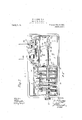
Referring to these drawings, Figure 1 is The type-wheel is thus p0- sitioned for printing in the appropriate the sections of Figs 3, 4 and 5; Figs. 8, 9 and 10 are detail views hereinafter referred to; Fig. .11 is a to view of a modified form of machine; and i s. 12 and 13 are detail views of portions 0 the mechanism shown i "in Fl ll.
v Re erring to Figs. 1 to 10 inclusive, the, machine consists ofa base-1 on which are mounted standards 2 3 and lfthe. standards 2 and 3 forming with a sheet-metal member 5a casing inclosing the number-wheels. In standards 2 and 3 are formed bearings for a rotatable shaft 6. Thestandards 3 and 4 are formed to support a rod 7 mounted in axial alinemeut with the shaft 6. Loosely mounted upon the shaft 6 are a plurality of collars 8 each of which carries a gear 9, the teeth of the latter numbering ten or a mul tiple of ten; in the present instance gears 9 are provided with thirty teeth 'for convenience and compactness'in construction. Adjacent .to each collar 8 and also loosely mounted upon shaft 6, is a collar 10 on each "of which is mounted agear 11; each gear lllies parallel and adjacent to. a gear 9, is of. thesanie size as'the corresponding gear 9' and has the same number of teeth. Adjacent/t0 each gear ll and on the side thereof opposite that on which the gear 9 lies, is a number-wheel 12, this consisting of a sheetmctal wheel having cars 13 extending inwardly and rivets -14 'coacting with these cars and the achacent gear 11 so'as to secure.95 the number-wheel to the gear 11. On the foutcr facc of each number-wheel are printed three successive series ofnunibers from zero to 9, so that a number is applied to the number-wheel 12 for each" space between two adjacent gear teeth upon the adjacent gear .11. In the casing 5 are a plurality of slots 15 one overlying each pair of gears 9 and '11, these slots being of a length equal to gears 9 and II. Adjacent. to each slot: 15 the casing-5 has a se 'ies of figures applied thereto beginning witi zero near the lower the machine on a plane at right angles to about ne-third the circumference of the.
end of the slot and ending with 9 at the upper end: of the slot, these figures correspending to the spaces between" the gear teeth showing through the adjacent slot 15; In the forward side of the casin are a plurality of openings 16 each over ying one of the number-wheels'12 so 'that one figure on each of the number-wheels 12 shows.
- through each of the openings 16.
and number-wheels 12 are not then operated.
..A type-wheel 22 is mounted upon shaft- 17 so as to rotate therewith but it may be -moved laterally uponshaft 17 by means of a spline 23. The type-wheel is mounted between two frame-pieces 24 which project upwardly from a base 25 and these frame- .pieces 24 carry two ink rollers 26 which when the type-wheel 22 is rotated eoaet with the printin faces formed upon the wheel so as to app y ink thereto for printing. Ex-
tending between the -'frame-pieces 24 .is a
The rod 7 is above described as extending between" the standards 3 and 4 in axial al ine ment with theshaft 6. Mounted on this rod so asto-rotate and to move axially thereon,
is an operating arm 30. The upper part of this arm'is provided with a lengthwise slot,
as shown in Fig. 8, -and in this slot are pivotally mounted two interlocked levers 31- and 32 each rovided witha'n operating handle 33. Ont e end of the lever 32 and below the .o rating handle thereof is a projection 34 a apted to enter the space between adjacent teeth on any pair ofgears 9 and 11. It will -be seen that arm may be moved laterally as desired uponthe rod 7 so as to' bring-theprojection 34 over. the desired pair of gears 9-and1 1; eitheron'e of the'handles'33 may then be depressed to carry the projection 34 into actio'n with the teeth of the underlying gears. 9 and 11;- and thpoperating arm- 30" may then .beturned'about rod 7 as. an axis, I
thus turning the ears 9 and and "the number-wheel 12 a red to the latter.
The means for mounting the operating arm 30 upon the rod 7 comprises two arms 35 lying one on either side of a member 36 which is movable freely upon the rod 7 and a rod 42 directly below the rod 7 and extending between the standards3 and 4. Member 36 carries a pin 37 which passes through a slot'38 ina lever 39 pivotally' mounted at 40 upon the base, of the .machine. In the lever 39 is a second slot (Fig. 2) which re-' ceives a-pin 41 projecting downwardly from the base 25 of the frame of the type-wheel 22. Thus, when the operating arm 30 is moved laterally to position it with reference to the appropriate pair of gears 9 and 11',
for the'rods 28 and 29 are .brackets 43 inv which is mounted. forrotation a shaft 44 carryinga paper-feeding roller 45. Thebrackets 43. are further extended rearwardly and carry the pivot pins-46 upon which links 47 are pivotally mounted. These links rota.- tably support a shaft 48 carrying a paperfeeding roller 49. A spring 50 is coiled about.
meet the pivot ins 46 andacts upon the adjacent link 47 in a direction to press the roller 49 against the roller 45. On the shafts 44 and 48 are intermeshing gears 51 hereby the two paper-feeding rollers arecaused to rotate simultaneously.
Pivotally mounted upon a 0st 52 projectmg from the standard 3 is a ell-crank lever 54 one end of which is adapted to be engaged and operated by the operatingarm 30. The other end of this bell-crank lever carries a pawl 55 which is held by aspring 56 in engagement with the periphery of a ratchet wheel 57, mounted upon the shaft 44 of the paper-feeding roll '45. A' spring. 58 acts upon the bell-drank lever 54 in a direction to hold it normally against a stop 59.
"Plvotally mounted upon a post 60 projecting from the standard 3 is a. lever 61 which is also adapted to-be engaged and operated bythe operating arm 30. Pivotally mounted'upon lever 61 near the rear end thereof is a pawl 62 one end of which is connected by a spring 63 .to'the end of the lever 61.
Pawl 62'has a toe 64 which is adapted to engage a stop pin 65 projecting outwardly from the standard3. The operating eud'of the pawl 62 is adapted to engage and operatea platen-carrying lever 36 loosely mounted upon the shaft 44 so as to rock thereon.
7 At .itslu'pper end lever 66 carries a plateni67, adapted'to coaet with'the paper strip and has... is
meet the'printing faces of the type-wheel 2:2 through the opening in the guard 27. spring 68 acts upon the lever 66 to normally hold the platen 6? in the position in which it is shown in Fig. 3.
Sec-uredto the base 1 are. supports 69 for a reel of paper tape .70 and the tape passes from this reel between the paperrfeeding rollers 45 and {19 and upward between the guard 27 and the platen 67.
Extending between the standards 2 and 3 and mounted for rotation in bearings forn'ied therein belpw and parallel to theshaft 17, is a shaft 71 having a plurality of eollars72 (Fig. 2) loosely mounted thereon. {hr each roller 72 is a inion' 73 meshing witha gear 11 and-havmg ten teeth; On
"each number-wheel 12 are three pins 75 sq positioned that asthenumb'er-wheel rotates the pin 75 will engage the teeth of the corresponding pinion 74 and each pin 75 will turn pinion 74 a distance equal to one tooth of the pinion. When pinion 7 1 is moved -thus it" causes a movementof a correspondmg extent of the pinion 73 ad acent thereto and as this p1n1on 1s 1n mesh with the gear 11 which is affixed to the number-wheel 12 next to the one which operated the pinion 7%, this movement of the pinion 74 a distance equal to one tooth will cause the number-wheel of the next higher order to be moved a distance equal to one number.
'In order to setall the number-wheels at and carries an operating handle 79. In the normal operation of the machlne, 1.1
move in such direction that the pawl 76 rides freely over the notch 78, but if it is desired to set all the inimber-wheels at zero,
it is only necessary to turn the handle 79 and with it shaft (i.until-thc wall of notch 78 engages each of the pawls 76 and by means of these pawls turns the gears 11 and number-wheels 12 until the Zeros on the inunher-wheels show through the openings 1Q iii-casing i y In order'to assist in properly positioning thenumber-wheels and to guard against accidental movement thereof I provide upon the base 1 a plurality of pivotally mounted 1 levers 80, one for each pair of gears 9 and 11, each lever carrying av roller 81. and being acted upon by a spring 82 to hold the roller 81 against the periphery of the gears 9 andllr Y V The operation of themachine, as thus constructed, will now be described.
If it be desiredto print on the tape a number consisting of twofdisrits the operating arm 30 is moved to the left until the projection 34 thereof lies over the second pair of gears 9 and--11 from the nght. As the arm is moved thus, the type-wheel will be correspondingly moved so that the printing faces thereon are in position to-p'rint, upon the paper tape in what will be the sec- 6nd column of figures upon the tape. Then, when the arm 30 is in this position it is rotated about the rodi7 until the projection 34: lies over the appropriate notchin the gears 9 and 11, as shown by the figures upon the casing 5 adjacent tothe slot through which the gears 9 and 11 may be seen. This having been done one of the handles 33 is depressed so that projection 34 will be carried into coaction with the gears 9'and 11; of the second pair from the right and arm 30 is then moved downwardly as far as it will go, thus carrying the second pair of gears 9 and 11 and the number wheel 12' corresponding thereto, with it. .Thus the second numberwheel, that is the number-wheel for the tens, will have been moved around a distance corresponding to the number of tens in the number to be printed and the number show- "ing through the opening 16 for the tens will have been increased by the number of tens in the number to be printed. \Vhen the gears 9 and 11 were turned thus the shaft 17 was 98 also turned a corresponding extent against the tension of the spring 19 by reason of the coaction of the gear-9 with the pinion 18 on shaft 17. Before this movement took place shaft 17 hadbeen held in such position by 100 spring 19 and stops 21 that the zero-on the type-wheel 22 was in position for printing,
so that the movement of shaft 17 efi'ectcd by geaix- 9 would carry the type around to the position for printing from the type'on Wheel eorres iamding to the number of teeth which the gears 9 and 11 wremoved. At
the end of the downwardrotational move ment of the operating arm 30, the latter engages the'lever (31 depressing the forward end thereof and raising the pawl (32; the pawl when thus operated, rocks lever 66 so as to retract the platen (l7 but when the toe 64.
of pawl (32 engages pin (35, the pawl is caused to release the lever 66 and the spring (SS 'ac'tuatcs lever (36 to cause the platen to strike ablow upoi'rthe-rear side at the paper strip 70, thus printing the figure upon the forward side of the strip. When this has been done the handle 33 is moved to withdraw the projection 34 from coaction 1 with the gears 9 and 11 and immediately spring 19 turns shaft 17 so as to turn the typeqvheel to the zero position. In doingthis the. pinion 18'causes the gear 9 to rolate butas gear 9 is movable independently of the gear 11, the lni'mber-wheel 12- is not actuated. The operating arm 30 is then -moved laterally into position with the projection 34L overthe first set of gears 9 and iw are.
ll for the units and the type-wheel is corres ondingly move'd laterally. The gears 9- an 11 are then operated by means ofthe,' projection 34: and the crating handle in the manner above described and the units number will then be printed upon the tape at the right of the tens number previously prlnted. This having been done the operof the corresponding pinion 74: and turn that pinion a distance equal to one tooth; in movin thus, the pinion 74 will corresponding y move the adjacent pinion 73 and since this pinion isin mesh with the gear 11 of thelnext adjacent number-wheel 12, the Y l which is to be carried -from one column to the next will be transferred to' the next' adjacent number-wheel 12 by a movementof that numbenwheeluequivalentto one number.
In Figs; 11, '12 and 13, I have shown a modification of my invention whereby the parts are more compactly arranged. In this embodiment of the invention the operating arm consists ofa bail 83 the arms of which are provi ed with openings through which the shaft extends, one of these arms lying adjacent to the standard 3 and the other arm lying adjacent to the standard Q. In the upper ace of the operating arm 83 is formed away adapted to receive a strip 84:.having rack-teeth formed thereon. This, =-rack 'meshes with a gear -85 mounted...;(m a stub shaft projecting upwardly from*the I in the arm 83. A pin 88 arm 83 and to .the car 85 is secured a pinion 86 meshingwit 1 a rack Sg'adapted to slide parallel to the rack 84 in a way'formed asses througlran opening in the rack Sean a lengthwiseslot in the arm 83, and to the lower end of this pin is secured a-projeet ion 89 which is adapted to enterthe spaces between adjacent teeth of the gears Q'and 11. -A spring 90 coiled about pinf88 between-the rack Betand the operating handle ofthe' pin, serves to normally hold the projection out of engagement with-the gears 9 and 11. To the rack.
8 7 is secured a laterally. extending arm 91 which at its end distant from the rack 87 issecured to a sleeve 92 adapted to slide upon the rod 7. The sleeve 92 is provided with a circumferential groove adapted to receive a sleeve 93 and to this sleeve is secured the frame 94 of the type-wheel 22.
It will thus be seen that when the handle 9 5 on the pin 88 is movedlaterally to' .pQ-i eltion the proJection 89 over the desired pairi.
on gears 9 and 11, the' printin wheel 22 will-be correspondingl moved 0 as to print .in the approprlate co umn, bu the lateral movement of the type-wheel isconsiderably less than that of the handle '95 because of the reduction eiiected-by the, gearing-between the two racks 84 and =87. I;
Having now described my invention, what I claim as newtherein and desire to secure by Letters Patent is as follow's'z 1. The combination of. a plurality of burn- --ber-wheels, a single manually-actuated joperating member for operating flll'0 f"'St'i'(l wheels, said member being movab e manually in one direction to earryit into coaetion with a number-wheel and in anothery'direction to operate the wheel, printingjmecb' h -a-nism comprising cooperatingfrinting.memebers, means'for moving one 0 members actuated in moving said operating saidprinting member into cotiperation Wltll' one ofsaid wheels, and means for movingone of said printing members actuatedjin movin --=sa"id operating member to move onef'o' wheels, substantially as set forth.
her-wheels, a single operating memberith ere- 2. The combination of a plurality of numfor which is freely movable manually: with respect to said Wheels, said membelflzbe'ing movable manually in one direction .tq'yca'r y it into coaction witha number-wheeldind' in another direction to-operate the l, printing mec hanism comprising 'eo'op t5 i'ng printing members, means: for 'movi'n of said printing members actuated mino' mg said operating member into-cooperation with one of said wheels, means for moving one of said printing members -actuated in moving said operating membe'r'to move one of said wheels, andmeans for actuating said printing mechanism to cause itto print, substantially asset forth.
3. The combination of a plurality of num; her-wheels, an operating 'member -=mov'a-ble into cooperation with-anyone of said'wheels and movable to operate the wheel, printing mechanism comprising cooperating pript ng members, means, for moving one of said printing members actuated in moving sen operating member into cooperation Withbfne a l u said printing members actuated in mov ng said. operating member. to move one Qcifsaid wheels, and means'actuated by-saidvvone'ra 7 ing memberfor 'actuatin said printing mechanism-to cause it to print, substantially as set forth p 4'. The combination off-n, ber-wheels, an operatifn plurality oi num} member movable H into cooperation with any one of said wheels and movable to-operate the wheel, printing mechanism comprising co'cipe'rating printin I members, "means -ior movmg oneof sai' Qprinting Inembe rsactuatedi'n -inoving said operating'inemberiinto cooperation with one of said wheels, means for moving oneof of said wheels, means for moving one of said printingmernbers actuated in moving said operating member to move'one of said wheels, a support for a paper-strip, means for actuatingthe printing mechanism to into cooperation with any one of said wheels and movable to operate the wheel, printing mechanism comprising cooperating printing members, means for moving one of said printing members actuated in moving said operating member into cooperation with one of said wheels, -means for moving one of said printing members actuated iii-moving said operating member to move one of said wheels, :1- support for a paper-strip, means actuatedby said-operating member for actuating the printing'mechanism to cause it to print on'the paper-strip, and means ac tuated by said operating member for feeding the paper-strip, substantially as set forth. 6. The combination of a plurality of number-wheels, means for causing each number.-
wheel in making ten-steps to operate the next adjacent number-wheel one step, a single nmnually-actuated operating inember ..for operat ng all ofsaid wheels, said member bemgmovable manually in one direction to carryit into ooaction with anumber-wheel.
and in another direction to operate'the wheel, printing mechanism comprising.cotiperating printing members, means for moving one' of said printing members actuated in-movin'g said operatii'ig member into cooperation with one of said 'Wheels, and means for moving one of said printing members actuated .in
anoving said operating member to move one of said wheels, substantially as set forth.
7. The combination of a plurality of number-wheels, a single manually-actuated oper ating member -for operating all oflsaid wheels, said member being movable manu ally in one direction to carry it into coaction.
with anumber-wheel and in another direction to operate the wheel, a p'airof printing members including a type wheelnnd' a platen, means for moving one of said= print ing members actuated .in moving saidoperating member into cooperation with one of said wheels,"means for rotating said typewvlieel by actuating said operating member to turn a number-wheeh a spring for returning the type-wheel, and a stop for arresting the type-wheel when in a predetermined position. substantially as set forth.
8. The combination of a plurality of mun-- ber vheels, an pperating member movable into cooperation with any one of said wheels,
a shaft geared to said wheels, :1 typ'e wheel splined on saidshaft, and a connection between said operating member and said typewlieel for moving the latter upon said shaft,
.substantially as set forth. a
9'. The combination of a plurality of numher-wheels, 'an operating member movable into cooperation with any one of said wheels,-
a shaft geared to said wheels, a type-wheel splined o'n'said shaft, a spring for turning number-wheels, an operatingmember mov-.
'able into cooperation with anyone of said wheels, a pa r of printing members including a type-wheel and cotiperatingplaten,
gearing between said number-wheels and said type-wheel for rotating the latter, and
a connection betweensaid operating member, and one of said print ng members for moving the latter, substantially as set forth.
11. Thevcombination of a plurality of number-wheels, a'n operating member movable into' cooperation with any one of said wheels, :1 pair of printing members including a type-wheel and cooperating platen,
gearing between said number-wheels and said type-wheel for. rotating the latter, a connection between said operating member and one of said printing members for moving tlielatter, and means for operating said printing members, substantially as set forth.
12. 'llieicombination. of a plurality of number-wheels, an operating member movable into cooperation with any one of said ,wheels, a pair of printing members including a. type-wheel and cotiperating platen, gearing between saidnum er-wheels and said type-wheel for rotating the latter, a connection between, said operating member and one of said printing membersfor moj' ingthe' latter, and means actuated by said operating member for actuating said printing members to cause them to print, substantially as set forth.
13. The combination of a plurality of number-wheels, an j operating member mov able intocooperation with any one of said wheels, a pair of printing members including a type-wheel and cooperating platen, gearing between saidnumber-wheels 'and stir'd. type-wheel for rotating the latter, a coimect'ion between said operating member and one of said printing members for'movmeal-is for'feeding the paper-strip, substan-- nui'nber-wheels', an operating member movable intocoiiperation with anyone of said 6 I v eudiia wheels, apair' of printing members including a-type-wheel and cod erating 'laten, gearing between said num er wheel s and said type-wheel for. rotating the latte a connection between 'said'operating member and one of said printing members for -movmg the latter,,-a support for a paper-strip,
means for actuating the printing members for-feeding the paper-strip, substantially as toeause them to print on the strip, and
means actuated bysaid operating member 1 set'forth.
" l numbenwheels, an' operating member=mov- I type-wheel spline sai operatin memberand'said type-wheel for moving-t ielatter-u on said shaft, andmeans for actuating t e type-wheel and 15. The combination of a plurality of able into cooperation with any one of said wheels, a shaft earedJ-to said wheels, :1
don said shaftfa platen e06 erating therewith, a connection between platen relatively to cause them to print, substantially asset forth.
16. The combination of. a plurality of number-wheels, an operating member .mov-
ableaintocoti eration with anyone of said.
wheels, a 'sha t geared to said wheels, a typewheel splined. on said shaft, a platen cooperating therewith, a connection between said operatin for moving the latter upon sai drshaft, and
means actuated by said operatin member for moving the type-wheel and p aten rela tively to cause them to print, substantially tational movement-ofsaid operating mem her, substantially as set forth. a
18. The combination of a plurality of number-wheels rotatable about an axis,-an operating member rotatable about said axis and movable laterally relatively to said wheels into coiiperative relation to any one of the wheels, a pair'of printing members including a type-wheel and cooperating platen, gearing between said number-wheelsand said type-Wheel for rotating'the latter, and a connection betwen"- sa1d operating member and one of said printing members whereby the latter will be positioned 'by-the lateral movement of the operating member,
substantially as set forth.
'.19. The combination of-a plurality"of;
numbenwheels rotatable about an axis, an
'sitioned by said shaft, a printing mem member and said type-wheel operating member rotatable about said axis,
and movable laterally relatively to said,
wheels into cooperative relation to any one of said wheels, means on said-member for engaging a number-wheel, a gear ad acent to eaehnumber-wheel and moved therewith by said member, a Shaft,'gea'rs thereon mesh-l ingwith said gears, a printing member pm cooperating therewith, and-a connection be-- tweenone lof said printing members and said operating member, substantially 'as setforth.
20. The ,combination of'aplurality of number-wheels rotatable' about. an axis, an operating member rotatable about, said axis and movable laterally relatively to said wheels into coiiperativerelation to any one of'said wheels, means on said' member.- for Y engaging a number-wheel, a gear adjacent.
to each number-wheel and moved therewith ing with said gears, atype-wheel splined on said shaft, 0. platen-cooperating. therewith,
and aconnection from said operating mem ber to'said type-wheel for moving the latter. upon said shaft, substantially as set forth. 21.- The. combination of a plurality 01f number-wheels'rotatable about an axis, an
operatingmember rotatable about said axis and movable laterally relatively to said wheels into cooperative relation-to any one of said wheels, means on said member-for engaging a number-wheel, a gear adj acent to each number-wheel'and'moved therewith by said member,'a shaft, gears thereon mesh-fing with said ears, a printing member po' sitioned-by sai shaft, a printing member'cooperating therewith, a connect-ion between one of said printing members and said operating member,-. a spring for ;turning said shaft in one direction, and a stop for arresting movement of said shaft under the ing' fluence of said spring, substantially as set forth. i
22.,The combination of aplurality of number-wheelsrotatableabout an axis, a.
'by'said member, a'sha'ft, gears thereon meshgear adjacent to each number-wheel and rotatable relatively to the numberqvheel about said axis," an operating member rotatable about, said axis and movable laterally relatively to said qwheels into cooperative relathe gear adjacent-thereto, a shaft, gears thereon meshing with said gears, and a printing member positioned bysaid shaft, substantially-asset forth.
23. The combination. of a plurality of number-wheels rotatable about jan axis, an
lit
tion to any on of said wheels, means on said .member for e gaging a number-wheel and operatiugniember rota-table about said axis and movable laterally? relafiaiely to said i wheels into cofiperati've relation to any one of the wheels, a pair of printing: members Includin'g a type-Wheel and cooperating platen,
isc
sa s,
gearing between said number-wheels and said type-wheel for rotating the latter, a
connection between said operating member and one of said printing members for mov-- ing the latter, and means for operating said printing members, substantially as set forth.
24. The combination of a plurality of number-wheelsrotatable about an axis, an operating member rotatable about said axis and movable laterally relatively to said wheels into co'dperative relation to any one of the wheels, a printing mechanism compris--' ,ingcoiiperating printing members,-,"ineans for moving one of said printing members ment of said operating member, and means in correspondence. with the lateral movement of said operating member, meansfor. moving one of said printing members .in c'orgespondence with the rotational moveactuated by said operating member for causing said printing mechanism to print, sub-= staiitially as set forth. V
25. The combination of a plurality of number-wheels rotatable about an axis, a manually-actuated operating member rotatable-about'the same axis and movable laterally relatively to said wheels into-cooperative -i'elation to any one of the .wheels, a printing mechanism comprising cooperating printing members, means for moving one of said printing members in correspondence with the lateral movement of said operating member, means for moving one of said printing" members .in correspondence with the rotational movemcntof said operating member, means tor supporting a sheet.
means for -feeding said sheet,-and means for;
operating said printing mechanism to cause it. to print on said sheet, substantially as set forth.
26. The combination'of a .plurality ;of
number-wheels rotatable about in-axis, a
manu'ally-actuated operating member" tatable about the same axis and movable laterally relatively to 'said' wheels into cooperative relation to any one of the wheels, means for causing each wheel in making ten steps to actuate the next adjacent wheel one step, cooperating printing members, means for moving one of. said printing members in correspondence-with the lateral movement of said operating member, and means for moving one of said printing members in correspondence with the rotational movement of said operating member, substantially as 'set forth.
27;"lhe combination of a plurality of number-wheels rotatable about an axis, an
operating member rotatable irbout'said axis and movable laterally relatively to said wheels i'iito cotiperatijte relation to any one of said wheels, means ()ILSflld member for engaging a number-wheel, agear adjacent to each numberewheel and moved therewith by said member, a' shaft,- gears thereon,
meshing with said gears,- a printing member positioned by said shaft, a printing member coopei'atingtherewith, a connection between one of said printing members and saidoperating member, and means actuatedj .by said 75, operating member forcausing said printing members to print,'substantially as set forth; 28. The combination of a plurality of number-wheels rotatable about an axis, an
operating memberrotatable about said axis and movable' laterally relatively to said wheels into cooperative relationto any one of said. wheels, means on said member for engaging a ninnberfwheel, a, gear adjacent to each number-wheel and moved therewith -30 by said member,- a shaft, gears thereon. meshing with said gears, a printing member positioned by'said shaft, a printing member.
, cooperating therewith, a connection between one of said printing members and said opeifatiiigmember, a support for a sheet, means for. operating said-f printing .members to cause them to print on said sheet, and means actuatedby said operating member for feeding said sheet, substantially as set forth.
29. The combination of a 'plurality of number-wheelsrotatable about an axis, a gear adjacent to each numberswheel and rotatable relatively to the number-wheel about said axis, an operating member ro- 95,
't-atabl'e about said axis and movable] *later- I ally relatively-to said wheels into cooperative relation to any one oi 'said wheels, means on -sa1d member for engaging a num-1 'ber-wheeland the gear adjacent thereto,- a 0 shaft, gears t liereonjmeshingwith said gears,- a.- spring for'turning said shaftin one direc-- tion, a stop for. arresting movement of the shaft when moved by the spring, and a printing memberpositioned by said shaft,
' substantially" as set forth 30. The combination of aiplurality of number-wheels rotatable .about an axis, a gear-adjacent to each number-wheel and rotatable relatively to" thenumber-wheel about said axis, an operating member romembers whereby the operating member when moved laterally will position theprintiiig member, and means for ope'ratingthe printing'niembersto-caiise themto print.
substantially-ass'etforth; r
31. The combination of .a plurality or.
numberrwhe'els rotatable about 'an axis, a gear adjacent 'to'. each number-wheel and rotatable'relatively to the numberwheel said member for engaging a number-wheel and the gear adjacent thereto, a shaft, gears thereon meshing with said gears, a-pair of rinting members one of which is positioned operating member for causingsaid printing a shaft,- a gear looselymounted on the shaft members to print, substantiallyas set forth.
, 32. The combination of a shaft, aplural *ity of number wheels loosely mountedthereon, a clutch between the shaftand each number-wheel, means for operating 'the adjacent toieach number-wheel, an operating ember rotatable about said axis and operative relation to any one of said wheels,
means on said member for engaging a num- -ber-wheel and the gear ad acentthereto, a
shaft, gears thereon -meshing with said gears, a pair ofpr nting members one of which is positioned by said last-named shaft,
and means for operating said printing members, substantially as set forth.
33. The combination of a plurality of number-wheels rotatable'aboutan axis, a
gearadjacent to eachnumbcr-wheel and rotatable relatively to the number-wheel about said axis, an operating member rotatable about said axis and movable laterally relatively to saidwheels into cooperative relation to any one of said wheels, means on said member for engaging a numberwheel and the gear adjacent thereto, a shaft, gears thereon meshing with said gears, a pair of printing members one of which is positioned by said shaft, means for operating said printing members. and-means for causing each number-wheel in making ten stepsto actuate the next adjacent numberwheel one step, substantially as set forth.
34. The combinatiorr of a plurality of number-wheels, a single manually-actuated operating member for operating all of said wheels, said member being movable manually in one direction to carry it into coaction with'a number-wheel and in another direction to operatetbc wheel. priut'ine mechanism comprising cooperating printin; members, means for moving one of said printing members actuated in moving said one 'atlng member into eo'e pcration with one of said wheels, means for moving one of said printing members actuated in moving said operating member to move. one of said wheels, and means for indicating the total actuation of said number-wheels, substantially as set forth.
35. The combination of a plurality of' number-wheels, an operatlng member mov-- able into cooperative relation-to anyone platen, gearing and said type-wheel for rotating the, latter,-
y said shaft, and meansaetuated by said wheels and movable to operate the wheel,
of said pair of printing members including a type-wheel and cooperating etween said number-wheels a connection between said operating .-men 1-'- her and one of said printing members-for moving the latter, and a casing forsaid 'number wheels having o'peningsgtherein 'through which one niimber'on' each wheel may beseen, substantially'as setforth.-- -,v
3 6; The combination I of a plurality of number-wheels rotatable about an. axis, a manually-actuated operating memberrotatable about the same axis and movable later-'- ally relativelyto said wheels into coiiperaac tive relation to any one of the wheels, a printing mechanism comprising cooperating printing members, means for moving one of said printing members in'correspondence movab e relatively to said wheels into cowith the lateral movement of said operating s5 member, means for moving one of said printing members in c0rresponde nce with the rotational movement ofsaid operating member, and means for indicating the total actuation of said number-wheels, substan- 9o tially as set forth 37. The combination of a plurality of number-wheels rotatable about an axis, an operating member rotatable about said axis and movable laterally -relatively to said wheels into coiiperative relation to any one ofvsaid wheels, means on said member for engaging a number-wheel, a gear adjacent to each number-wheel and-moved therewith by said member. a shaft, gears thereon meshing with said gears, a printing member positioned by saidshaft, a printing member cooperating therewith, a connection betweenone of said printing members and said operating member, means for actuating the printing members to cause them to'print, and means for indicating the total actuation of said number-wheels, substantially as set forth.
38. The combination of a plurality of number-wheels. a single "manually-actuated operating member for operating all of said wheels. said memberbeing-movable manually in one direction to carry it into coaction with "a number-wheel and in another direction to' operate the wheel, printing meclmnism comprising cooperating printing members, meansaetuated in moving said opcrating member into cooperation with one'of said wheels for moving one of said printing 0 members a distance less than but bearing a predetermined relation to the movement of said member, and'means for moving one of said printing members actuated in moving said operating men'iber to move one ofa'id wheels. substantially as set forth. 39. The combination of a plurality of number-wheels, an operating member, movable into cooperation with any one of said 3'0 said type-whee'l for rotating the latter, a --connect1on between said operating member printing mechanism comprising cooperating prmtin members, means actuated 1n mbvmg sa1 operating member into cooperation with one of said wheels for moving one of said printing members a distance less than but bearing, a predetermined relation to the ,movement of said member, means for movin'g one of said printing members actuated in moving said operating member to move one of said wheels, and means actuated by said operating member for actuating said rinting mechanism to cause it to print, su stantially as setdorth;
40. The combination of a plurality of number-wheels, an operating member movable into-coiiperationwith any one of said wheels, a shaft geared to said wheels, a type- .wheel splined on said shaft, and a connection between said operating member and said type-wheel for moving the latter upon said shaft when said member is'moved a distance less than but-bearing a predetermined.
relatibn to'the movement of said member,
substantially as set forth.
41. The combination of a plurality of number-wheels, an operating member movable into cooperation with any one of said wheels, a pair of printing members includmg a type-wheeland coiiperatmg platen, gearing between said number-wheels and and one of said printing members for moving the latter when said member is moved a distance less-than but bearing a predetermined relation to the. movement of said member, and means actuated by said operating member for actuating said printing members to cause them toiprint, substantially asset forth.
42. The combination of a plurality of number-wheels rotatable about an axis, an operating member rotatable about said axisand movable laterally relatively to said wheels into cooperative relation to any one of said wheels,-means on said member for engaging a number-wheel, a gear adjacent to each number-wheel and moved therewith by said member, a shaft, gears thereon meshing with said gears, 21 type-wheel splined on saidv shaft, a platen cooperating therewith, and a connection from said operating member to.
said type-wheel for moving the latter upon said shaft when said member is 'moved a distance less than butdirectly proportioned to the movement of the member, substantially as set forth.
43. The combination of a plurality of number-wheels, a single manually-actuated operating member movable freely with respectto said wheels to cause it to directly engage any one of the .wheels at any point thereon between predetermined limits and to cause it to rotate the wheel engaged thereby,
print ing mechanism comprising cooperating number-wheels, a single manually-actuated operating member movable. about the axis of said-wheels and movable freely with respect to the wheels to cause it to direetly'engage any one of the wheels "at any point thereon between predetermined limits, printing mechanism comprising cooperating printing members, means for moving one of said printing members actuated in moving said operating member to cause it-to' engage one of said wheels, and means for moving one ofsaid printing members actuated in rotatin said operating member about the axis of said wheels, substantially as set forth.
- This specification signed and witnessed this 28th dayv of September, 1909.
WILLIAM P. QUENTELL; Witnesses: I
E. S. Yonnos, FRANKLIN JUDGE.-
Priority Applications (1)
| Application Number | Priority Date | Filing Date | Title |
|---|---|---|---|
| US52052709A US950114A (en) | 1909-10-01 | 1909-10-01 | Computing-machine. |
Applications Claiming Priority (1)
| Application Number | Priority Date | Filing Date | Title |
|---|---|---|---|
| US52052709A US950114A (en) | 1909-10-01 | 1909-10-01 | Computing-machine. |
Publications (1)
| Publication Number | Publication Date |
|---|---|
| US950114A true US950114A (en) | 1910-02-22 |
Family
ID=3018528
Family Applications (1)
| Application Number | Title | Priority Date | Filing Date |
|---|---|---|---|
| US52052709A Expired - Lifetime US950114A (en) | 1909-10-01 | 1909-10-01 | Computing-machine. |
Country Status (1)
| Country | Link |
|---|---|
| US (1) | US950114A (en) |
-
1909
- 1909-10-01 US US52052709A patent/US950114A/en not_active Expired - Lifetime
Similar Documents
| Publication | Publication Date | Title |
|---|---|---|
| US1214886A (en) | Carrying-over and clearing mechanism for calculating-machines. | |
| US1295307A (en) | Platen mechanism for accounting-machines. | |
| US1152582A (en) | Departmental cash-register. | |
| US992592A (en) | Calculating-machine. | |
| US1313958A (en) | Assigitob to the national cash b-sgistee | |
| US1260061A (en) | Calculating-machine. | |
| US1077220A (en) | Calculating and printing machine. | |
| US1338876A (en) | skerl and f | |
| US1039614A (en) | Calculating-machine. | |
| US1400106A (en) | Adding-machine | |
| US1940949A (en) | Ticket or check issuing machine | |
| US464294A (en) | Cash register | |
| US1168745A (en) | Calculating-machine. | |
| US1707094A (en) | Adding machine | |
| US1293094A (en) | Adding-machine. | |
| US435318A (en) | Recording-machine | |
| US924298A (en) | Calculating-machine. | |
| US1428407A (en) | Resetting mechanism | |
| US1153129A (en) | Adding-machine. | |
| US1166995A (en) | Autographic register. | |
| US1797995A (en) | Chusetts | |
| US635860A (en) | Cash-register. | |
| US817725A (en) | Cash-register. | |
| US1252704A (en) | Adding-machine. | |
| US1151747A (en) | Check-printer attachment for cash-registers. |