US9500089B2 - Rotary energy generating system and corresponding device - Google Patents

Rotary energy generating system and corresponding device Download PDF

Info

Publication number
US9500089B2
US9500089B2 US13/681,532 US201213681532A US9500089B2 US 9500089 B2 US9500089 B2 US 9500089B2 US 201213681532 A US201213681532 A US 201213681532A US 9500089 B2 US9500089 B2 US 9500089B2
Authority
US
United States
Prior art keywords
rotor
lifter
energy generating
rotary energy
paddle
Prior art date
Legal status (The legal status is an assumption and is not a legal conclusion. Google has not performed a legal analysis and makes no representation as to the accuracy of the status listed.)
Active, expires
Application number
US13/681,532
Other versions
US20130142635A1 (en
Inventor
Louie Edwards
Current Assignee (The listed assignees may be inaccurate. Google has not performed a legal analysis and makes no representation or warranty as to the accuracy of the list.)
Individual
Original Assignee
Individual
Priority date (The priority date is an assumption and is not a legal conclusion. Google has not performed a legal analysis and makes no representation as to the accuracy of the date listed.)
Filing date
Publication date
Application filed by Individual filed Critical Individual
Priority to US13/681,532 priority Critical patent/US9500089B2/en
Publication of US20130142635A1 publication Critical patent/US20130142635A1/en
Application granted granted Critical
Publication of US9500089B2 publication Critical patent/US9500089B2/en
Active legal-status Critical Current
Adjusted expiration legal-status Critical

Links

Images

Classifications

    • FMECHANICAL ENGINEERING; LIGHTING; HEATING; WEAPONS; BLASTING
    • F01MACHINES OR ENGINES IN GENERAL; ENGINE PLANTS IN GENERAL; STEAM ENGINES
    • F01DNON-POSITIVE DISPLACEMENT MACHINES OR ENGINES, e.g. STEAM TURBINES
    • F01D5/00Blades; Blade-carrying members; Heating, heat-insulating, cooling or antivibration means on the blades or the members
    • F01D5/30Fixing blades to rotors; Blade roots ; Blade spacers
    • FMECHANICAL ENGINEERING; LIGHTING; HEATING; WEAPONS; BLASTING
    • F01MACHINES OR ENGINES IN GENERAL; ENGINE PLANTS IN GENERAL; STEAM ENGINES
    • F01CROTARY-PISTON OR OSCILLATING-PISTON MACHINES OR ENGINES
    • F01C1/00Rotary-piston machines or engines
    • F01C1/02Rotary-piston machines or engines of arcuate-engagement type, i.e. with circular translatory movement of co-operating members, each member having the same number of teeth or tooth-equivalents
    • F01C1/06Rotary-piston machines or engines of arcuate-engagement type, i.e. with circular translatory movement of co-operating members, each member having the same number of teeth or tooth-equivalents of other than internal-axis type
    • FMECHANICAL ENGINEERING; LIGHTING; HEATING; WEAPONS; BLASTING
    • F01MACHINES OR ENGINES IN GENERAL; ENGINE PLANTS IN GENERAL; STEAM ENGINES
    • F01CROTARY-PISTON OR OSCILLATING-PISTON MACHINES OR ENGINES
    • F01C21/00Component parts, details or accessories not provided for in groups F01C1/00 - F01C20/00
    • F01C21/08Rotary pistons
    • F01C21/0809Construction of vanes or vane holders
    • F01C21/0818Vane tracking; control therefor
    • F01C21/0827Vane tracking; control therefor by mechanical means
    • F01C21/0836Vane tracking; control therefor by mechanical means comprising guiding means, e.g. cams, rollers
    • FMECHANICAL ENGINEERING; LIGHTING; HEATING; WEAPONS; BLASTING
    • F01MACHINES OR ENGINES IN GENERAL; ENGINE PLANTS IN GENERAL; STEAM ENGINES
    • F01CROTARY-PISTON OR OSCILLATING-PISTON MACHINES OR ENGINES
    • F01C21/00Component parts, details or accessories not provided for in groups F01C1/00 - F01C20/00
    • F01C21/08Rotary pistons
    • F01C21/0809Construction of vanes or vane holders
    • F01C21/089Construction of vanes or vane holders for synchronised movement of the vanes
    • FMECHANICAL ENGINEERING; LIGHTING; HEATING; WEAPONS; BLASTING
    • F01MACHINES OR ENGINES IN GENERAL; ENGINE PLANTS IN GENERAL; STEAM ENGINES
    • F01DNON-POSITIVE DISPLACEMENT MACHINES OR ENGINES, e.g. STEAM TURBINES
    • F01D1/00Non-positive-displacement machines or engines, e.g. steam turbines
    • F01D1/02Non-positive-displacement machines or engines, e.g. steam turbines with stationary working-fluid guiding means and bladed or like rotor, e.g. multi-bladed impulse steam turbines
    • F01D1/026Impact turbines with buckets, i.e. impulse turbines, e.g. Pelton turbines
    • FMECHANICAL ENGINEERING; LIGHTING; HEATING; WEAPONS; BLASTING
    • F01MACHINES OR ENGINES IN GENERAL; ENGINE PLANTS IN GENERAL; STEAM ENGINES
    • F01DNON-POSITIVE DISPLACEMENT MACHINES OR ENGINES, e.g. STEAM TURBINES
    • F01D7/00Rotors with blades adjustable in operation; Control thereof
    • FMECHANICAL ENGINEERING; LIGHTING; HEATING; WEAPONS; BLASTING
    • F04POSITIVE - DISPLACEMENT MACHINES FOR LIQUIDS; PUMPS FOR LIQUIDS OR ELASTIC FLUIDS
    • F04CROTARY-PISTON, OR OSCILLATING-PISTON, POSITIVE-DISPLACEMENT MACHINES FOR LIQUIDS; ROTARY-PISTON, OR OSCILLATING-PISTON, POSITIVE-DISPLACEMENT PUMPS
    • F04C2210/00Fluid
    • F04C2210/22Fluid gaseous, i.e. compressible
    • F04C2210/227Steam
    • FMECHANICAL ENGINEERING; LIGHTING; HEATING; WEAPONS; BLASTING
    • F05INDEXING SCHEMES RELATING TO ENGINES OR PUMPS IN VARIOUS SUBCLASSES OF CLASSES F01-F04
    • F05DINDEXING SCHEME FOR ASPECTS RELATING TO NON-POSITIVE-DISPLACEMENT MACHINES OR ENGINES, GAS-TURBINES OR JET-PROPULSION PLANTS
    • F05D2220/00Application
    • F05D2220/30Application in turbines
    • F05D2220/31Application in turbines in steam turbines

Definitions

  • the present invention relates to the field of energy generating systems, and more particularly, to a rotary energy generating system.
  • U.S. published patent application no. 2010/0215484 discloses a turbine comprising a housing, a shaft rotatably supported in the housing about an axis of rotation, and a wheel with a plurality of turbine blades supported in a chamber by the shaft for rotation with the shaft.
  • High pressure gas such as steam, is directed into the housing through an inlet so that the gas impinges the blades to induce rotation of the wheel about the shaft.
  • This rotary steam engine includes a circular casing with side walls defining an interior cylindrical section wherein a rotor rotates therein.
  • the rotor includes a hub, radial spokes, and a circular rim. Extending from an outer periphery of the rim is a series of spaced transverse lobes extending from side wall to side wall within the casing.
  • the casing includes a series of spaced spring-biased transverse vanes to engage the outer periphery, seals and lobes of the rotor.
  • a series of chambers are defined by the seals and lobes, outer periphery of the rotor, the inner periphery of the casing and the side walls.
  • a series of steam inlet and exhaust steam outlet pairs communicate with the chambers as the rotor is rotated by expansion of live steam against the vanes in the chambers.
  • a rotary energy generating device comprising an output shaft, a rotor coupled to the output shaft, and a plurality of paddles coupled to the rotor, with each paddle being moved between vertical and horizontal positions as the rotor is rotated.
  • a chamber housing may include a plurality of inlet and output pairs.
  • a respective open chamber area may be defined between each inlet and outlet pair based on a given rotation direction of the rotor, with each respective open chamber area configured to receive the plurality of paddles in the vertical position as the rotor rotates in the given rotation direction.
  • a respective slotted chamber area may be defined between each outlet and inlet pair based on the given rotation direction of the rotor, with each respective slotted chamber area configured to receive the plurality of paddles in the horizontal position as the rotor rotates in the given rotation direction.
  • Each inlet may be configured to receive a pressurized fluid, such as steam or gas, for example, to push a paddle through a respective open chamber area.
  • a pressurized fluid such as steam or gas
  • Each outlet may be configured to exhaust the pressurized fluid after the paddle has been pushed through a respective slotted chamber area.
  • a plurality of lifters may be carried by the rotor, with each paddle having a lifter coupled thereto.
  • a plurality of backstops may be carried by the rotor, with each lifter having a respective backstop associated therewith.
  • each lifer may comprise a threaded section
  • each paddle may comprise a handle extending outwards therefrom, with the handle comprising a threaded section for engaging the threaded section of a respective lifter.
  • each lifer may include a recessed pocket, and a roller bearing assembly that moves up and down in the recessed pocket.
  • Each paddle may comprise a handle extending outwards therefrom, and a lever coupled between the handle and the roller bearing assembly of each lifter.
  • Each lifter may comprises an upper bearing carried by an upper end thereof, and a lower bearing carried by an opposing lower end thereof.
  • the rotary energy generating device may further include a fixed upper guide rail contacting the upper guide bearings of the plurality of lifters, and a fixed lower guide rail contacting the lower guide bearings of the plurality of lifters.
  • the fixed upper and lower guide rails may be configured to guide the plurality of lifers for moving the paddles between the vertical and horizontal positions as the rotor is rotated.
  • the fixed upper and lower guide rails may be coupled to the chamber housing.
  • Each paddle may be circular shaped, and each respective open chamber area may also be circular.
  • Another aspect of the present invention is to provide a rotary energy generating system comprising a steam generator, a rotary energy generating device coupled to the steam generator, and an electrical generator coupled to the output shaft of the rotary energy generating device.
  • the rotary energy generating device may be configured as described above.
  • FIG. 1 is a block diagram of a rotary energy generating system in accordance with the present invention.
  • FIG. 2 is a perspective view of the rotary energy illustrated in FIG. 1 .
  • FIG. 3 is a partial cut-away view of the rotary engine in accordance with the present invention.
  • FIG. 4 is a perspective view of the chamber section of the rotary energy in accordance with the present invention.
  • FIG. 5 is a partial cut-away view of the chamber section illustrated in FIG. 4 .
  • FIG. 6 is a perspective sectional view of a lower half of the chamber section of the rotary engine including a portion of the rotor section in accordance with the present invention.
  • FIG. 7 is a perspective view of the rotor of the rotary energy in accordance with the present invention.
  • FIG. 8 is a perspective sectional view of the rotor of the rotary energy including the paddles and lifters in accordance with the present invention.
  • FIGS. 9 a and 9 b are side perspective views of a paddle and corresponding lifter illustrated in FIG. 8 .
  • FIG. 10 is a perspective view of the rotor section of the rotary energy without the chamber section in accordance with the present invention.
  • FIG. 11 is a perspective sectional view of the rotor of the rotary energy including another embodiment of the paddles and lifters in accordance with the present invention.
  • FIGS. 12 a and 12 b are side perspective views of a paddle and corresponding lifter illustrated in FIG. 11 .
  • a rotary energy generating system 10 includes a rotary energy generating device 30 coupled between a steam generator 20 and an electrical generator 40 .
  • the rotary energy generating device 30 may also be referred to as a rotary engine.
  • the rotary energy generating device 30 is steam powered, and is used to operate the electrical generator 40 to generate electricity.
  • the rotary energy generating device 30 includes a rotor section 50 and a chamber section 70 surrounding the rotor section.
  • high pressure steam may be used to power the rotary engine 30 , such as other types of high pressure fluids or gases. These fluids or gases may also be combustible.
  • the rotary energy generating device 30 is not limited to operating an electrical generator, and may be used to operate other types of devices and machines.
  • the chamber section 70 is circular shaped and includes a pair of inlets 72 for receiving the steam from the steam generator 20 , and a corresponding pair of outlets 74 for outputting the received steam.
  • the received steam is used to turn a circular rotor within the rotor section 50 that is coupled to an output shaft 52 that interfaces with the electrical generator 40 .
  • the actual number of inlets 72 and outlets 74 , as well as the size of the rotary engine 30 will vary based on the intended application.
  • the rotor section 50 includes a rotor assembly comprising a rotor 54 , paddles 56 ( 1 )- 56 ( 6 ) rotatably coupled to the rotor, lifters 58 ( 1 )- 58 ( 6 ) carried by the rotor for causing the paddles to move between vertical and horizontal positions, and upper and lower guide rails 60 , 62 for guiding the lifters as they rotate with the rotor.
  • the upper and lower guide rails 60 , 62 are stationary since they are attached to the chamber section or housing 70 .
  • the paddles 56 ( 1 )- 56 ( 6 ) will be generally indicated by reference 56 .
  • the lifters 58 ( 1 )- 58 ( 6 ) will be generally indicated by reference 58 .
  • the chamber section 70 includes two different chamber areas, open chamber areas 76 and slotted chamber areas 78 .
  • the two chamber areas are alternately positioned within the chamber section 70 .
  • As steam enters the inlets 72 a portion of the paddles 56 are pushed within the open chamber areas 76 .
  • the paddles 56 move between a vertical position when in the open chamber area 76 , and a horizontal position when in the slotted chamber area 78 . Movement of the paddles 56 is based on position of the lifters 58 traveling along the upper and lower rails 60 , 62 .
  • the chamber section 70 will now be discussed in greater detail in reference to FIGS. 4, 5 and 6 .
  • the illustrated chamber section 70 there are two open chamber areas 76 and two slotted chamber areas 78 .
  • the actual number of open and slotted chamber areas 76 , 78 will vary depending on the intended application.
  • the open chamber area 76 is defined between an inlet 72 and outlet 74 since this area receives the steam.
  • the slotted chamber area 78 is also defined between an outlet 74 and an inlet 72 , but does not receive any steam.
  • the paddles 56 move to the vertical position when in the open chamber area 76 , as indicated by paddles 56 ( 1 ) and 56 ( 4 ).
  • the open chamber area 76 has a circular shape to match the shape of the paddles 56 .
  • the illustrated paddles 56 are circular-shaped, other shapes are readily acceptable.
  • a tight seal is created between the outer surfaces of each paddle 56 and the interior walls of the open chamber area 76 so as to make more efficient use of the steam.
  • the slot within the slotted chamber area 78 is sized to match or slightly exceed a thickness or width of the paddles 56 .
  • the function of the slotted chamber area 78 is to allow the steam to exit through the outlet 74 , and to allow the paddles 56 to move to the next open chamber area 76 , as indicated by paddles 56 ( 3 ) and 56 ( 6 ).
  • the paddles 56 enter the open chamber area 76 they are then moved by the lifters 58 from the horizontal position to the vertical position, as indicated by paddles 56 ( 1 ) and 56 ( 4 ).
  • the beginning of the slot within the slotted chamber area 78 may be wedge-shaped or tapered so as to more easily receive the paddles 56 in the horizontal position.
  • the rotor section 50 includes the rotor 54 that is configured to carry 6 paddles 56 ( 1 )- 56 ( 6 ).
  • the actual number of paddles can vary based on the intended application, as readily appreciated by those skilled in the art.
  • Each paddle 56 is to be inserted through a side opening 57 in the rotor 54 .
  • Each paddle 56 includes a handle 64 that extends through a respective side opening 57 .
  • Roller bearings are at the end of the handles 64 to assist with movement of the paddles 56 .
  • roller bearings surround the handle 64 adjacent the side openings 57 to also assist with movement of the paddles 56 .
  • the rotor 54 has an open lift assembly area 65 for a lifter assembly that includes a lifter 58 and a corresponding backstop 59 that contacts the lifter.
  • Each handle 64 includes a threaded section 80 that operates as a gear in response to a corresponding threaded section 82 on the lifter 58 that also operates as a gear.
  • the paddle 64 is moved to the horizontal position.
  • the paddle 64 is moved to the vertical position.
  • Each backstop 59 is fixably attached to the rotor 54 within the open lift assembly area 65 .
  • Each backstop 59 includes a series of rollers 84 to assist with movement of the lifter 58 between the up and down positions.
  • each lifter 58 includes a roller bearing 86 .
  • the roller bearings 86 move along the upper and lower guide rails 60 and 62 , as illustrated in FIG. 10 with the chamber section not being shown. However, the upper and lower guide rails 60 , 62 do not rotate, and are fixably coupled to the chamber section 50 .
  • the upper and lower rails guide rails 60 , 62 include first sections 90 , 100 that cause the lifters 58 to move the paddles 56 to the horizontal position, and second sections 92 , 102 that cause the lifters 58 to move the paddles 56 to the vertical position.
  • lifters 58 ( 1 ) and 58 ( 4 ) are positioned along the first sections 92 , 102 so that the paddles 56 ( 1 ) and 56 ( 4 ) are in the vertical position.
  • Lifters 58 ( 2 ), 58 ( 3 ), 58 ( 5 ) and 58 ( 6 ) are positioned along the second sections 92 , 102 so that the paddles 56 ( 2 ), 56 ( 3 ), 56 ( 5 ) and 56 ( 6 ) are in the horizontal position.
  • transition sections 94 , 104 are transition sections 94 , 104 .
  • the rotor 54 rotates. As the rotor 54 rotates, the lifters 58 move along the upper and lower guide rails 60 , 62 causing the paddles 56 to move between the vertical and horizontal position.
  • FIGS. 11, 12 a and 12 b An alternative embodiment of the paddles 56 ′ and lifters 58 ′ will now be discussed in reference to FIGS. 11, 12 a and 12 b .
  • the corresponding threaded sections are replaced by a lever 110 ′ that has one end coupled to the frame 64 ′.
  • the other end of the lever 110 ′ is coupled to a roller bearing assembly 112 ′ that moves up and down within a recessed pocket 114 ′ formed in the lifter 58 ′.
  • the roller bearing assembly 112 ′ includes a roller bearing 118 ′ contacting the sidewalls of the recessed pocket 114 ′.

Landscapes

  • Engineering & Computer Science (AREA)
  • Mechanical Engineering (AREA)
  • General Engineering & Computer Science (AREA)
  • Engine Equipment That Uses Special Cycles (AREA)

Abstract

A rotary energy generating device includes an output shaft, a rotor coupled to the output shaft, and a plurality of paddles coupled to the rotor, with each paddle being moved between vertical and horizontal positions as the rotor is rotated. A chamber housing includes inlet and output pairs. A respective open chamber area is defined between each inlet and outlet pair based on a given rotation direction of the rotor, with each respective open chamber area configured to receive the paddles in the vertical position as the rotor rotates in the given rotation direction. A respective slotted chamber area is defined between each outlet and inlet pair based on the given rotation direction of the rotor, with each respective slotted chamber area configured to receive the paddles in the horizontal position as the rotor rotates in the given rotation direction.

Description

RELATED APPLICATIONS
This application claims the benefit of U.S. Provisional Application Ser. No. 61/562,553 filed Nov. 22, 2011, the entire contents of which are incorporated herein by reference.
FIELD OF THE INVENTION
The present invention relates to the field of energy generating systems, and more particularly, to a rotary energy generating system.
BACKGROUND OF THE INVENTION
There are a variety of energy generating systems, including those operating with steam turbines, for example. Large scale steam turbines produce electricity but at a relatively low efficiency rate.
Smaller scale turbines can operate with greater efficiency. For example, U.S. published patent application no. 2010/0215484 discloses a turbine comprising a housing, a shaft rotatably supported in the housing about an axis of rotation, and a wheel with a plurality of turbine blades supported in a chamber by the shaft for rotation with the shaft. High pressure gas, such as steam, is directed into the housing through an inlet so that the gas impinges the blades to induce rotation of the wheel about the shaft.
Another type of energy generating system is one operating with a rotary steam engine, as disclosed in U.S. Pat. No. 4,115,045. This rotary steam engine includes a circular casing with side walls defining an interior cylindrical section wherein a rotor rotates therein. The rotor includes a hub, radial spokes, and a circular rim. Extending from an outer periphery of the rim is a series of spaced transverse lobes extending from side wall to side wall within the casing. The casing includes a series of spaced spring-biased transverse vanes to engage the outer periphery, seals and lobes of the rotor. A series of chambers are defined by the seals and lobes, outer periphery of the rotor, the inner periphery of the casing and the side walls. A series of steam inlet and exhaust steam outlet pairs communicate with the chambers as the rotor is rotated by expansion of live steam against the vanes in the chambers.
Even in view of known energy generating systems that are an alternative to those operating with large scale steam turbines, there is still a need to provide other configurations of energy generating systems that are efficient and straightforward to operate.
SUMMARY OF THE INVENTION
In view of the foregoing background, it is therefore an object of the present invention to provide a rotary energy generating device that is efficient and straightforward to operate.
This and other objects, features, and advantages in accordance with the present invention are provided by a rotary energy generating device comprising an output shaft, a rotor coupled to the output shaft, and a plurality of paddles coupled to the rotor, with each paddle being moved between vertical and horizontal positions as the rotor is rotated.
A chamber housing may include a plurality of inlet and output pairs. A respective open chamber area may be defined between each inlet and outlet pair based on a given rotation direction of the rotor, with each respective open chamber area configured to receive the plurality of paddles in the vertical position as the rotor rotates in the given rotation direction. A respective slotted chamber area may be defined between each outlet and inlet pair based on the given rotation direction of the rotor, with each respective slotted chamber area configured to receive the plurality of paddles in the horizontal position as the rotor rotates in the given rotation direction.
Each inlet may be configured to receive a pressurized fluid, such as steam or gas, for example, to push a paddle through a respective open chamber area. Each outlet may be configured to exhaust the pressurized fluid after the paddle has been pushed through a respective slotted chamber area.
A plurality of lifters may be carried by the rotor, with each paddle having a lifter coupled thereto. A plurality of backstops may be carried by the rotor, with each lifter having a respective backstop associated therewith.
In one embodiment, each lifer may comprise a threaded section, and each paddle may comprise a handle extending outwards therefrom, with the handle comprising a threaded section for engaging the threaded section of a respective lifter.
In another embodiment, each lifer may include a recessed pocket, and a roller bearing assembly that moves up and down in the recessed pocket. Each paddle may comprise a handle extending outwards therefrom, and a lever coupled between the handle and the roller bearing assembly of each lifter.
Each lifter may comprises an upper bearing carried by an upper end thereof, and a lower bearing carried by an opposing lower end thereof. The rotary energy generating device may further include a fixed upper guide rail contacting the upper guide bearings of the plurality of lifters, and a fixed lower guide rail contacting the lower guide bearings of the plurality of lifters. The fixed upper and lower guide rails may be configured to guide the plurality of lifers for moving the paddles between the vertical and horizontal positions as the rotor is rotated.
The fixed upper and lower guide rails may be coupled to the chamber housing. Each paddle may be circular shaped, and each respective open chamber area may also be circular.
Another aspect of the present invention is to provide a rotary energy generating system comprising a steam generator, a rotary energy generating device coupled to the steam generator, and an electrical generator coupled to the output shaft of the rotary energy generating device. The rotary energy generating device may be configured as described above.
BRIEF DESCRIPTION OF THE DRAWINGS
FIG. 1 is a block diagram of a rotary energy generating system in accordance with the present invention.
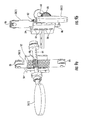
FIG. 2 is a perspective view of the rotary energy illustrated in FIG. 1.
FIG. 3 is a partial cut-away view of the rotary engine in accordance with the present invention.
FIG. 4 is a perspective view of the chamber section of the rotary energy in accordance with the present invention.
FIG. 5 is a partial cut-away view of the chamber section illustrated in FIG. 4.
FIG. 6 is a perspective sectional view of a lower half of the chamber section of the rotary engine including a portion of the rotor section in accordance with the present invention.
FIG. 7 is a perspective view of the rotor of the rotary energy in accordance with the present invention.
FIG. 8 is a perspective sectional view of the rotor of the rotary energy including the paddles and lifters in accordance with the present invention.
FIGS. 9a and 9b are side perspective views of a paddle and corresponding lifter illustrated in FIG. 8.
FIG. 10 is a perspective view of the rotor section of the rotary energy without the chamber section in accordance with the present invention.
FIG. 11 is a perspective sectional view of the rotor of the rotary energy including another embodiment of the paddles and lifters in accordance with the present invention.
FIGS. 12a and 12b are side perspective views of a paddle and corresponding lifter illustrated in FIG. 11.
DETAILED DESCRIPTION OF THE PREFERRED EMBODIMENTS
The present invention will now be described more fully hereinafter with reference to the accompanying drawings, in which preferred embodiments of the invention are shown. This invention may, however, be embodied in many different forms and should not be construed as limited to the embodiments set forth herein. Rather, these embodiments are provided so that this disclosure will be thorough and complete, and will fully convey the scope of the invention to those skilled in the art. Like numbers refer to like elements throughout, and prime notations are used to indicate similar elements in alternative embodiments.
Referring initially to FIGS. 1 and 2, a rotary energy generating system 10 includes a rotary energy generating device 30 coupled between a steam generator 20 and an electrical generator 40. The rotary energy generating device 30 may also be referred to as a rotary engine. For illustration purposes, the rotary energy generating device 30 is steam powered, and is used to operate the electrical generator 40 to generate electricity. The rotary energy generating device 30 includes a rotor section 50 and a chamber section 70 surrounding the rotor section.
As readily appreciated by those skilled in the art, alternatives to high pressure steam may be used to power the rotary engine 30, such as other types of high pressure fluids or gases. These fluids or gases may also be combustible. The rotary energy generating device 30 is not limited to operating an electrical generator, and may be used to operate other types of devices and machines.
The chamber section 70 is circular shaped and includes a pair of inlets 72 for receiving the steam from the steam generator 20, and a corresponding pair of outlets 74 for outputting the received steam. The received steam is used to turn a circular rotor within the rotor section 50 that is coupled to an output shaft 52 that interfaces with the electrical generator 40. The actual number of inlets 72 and outlets 74, as well as the size of the rotary engine 30, will vary based on the intended application.
Referring now to a partial cut-away view of the rotary energy generating device 30, as provided in FIG. 3, the rotor and chamber sections 50, 70 will be generally discussed. The rotor section 50 includes a rotor assembly comprising a rotor 54, paddles 56(1)-56(6) rotatably coupled to the rotor, lifters 58(1)-58(6) carried by the rotor for causing the paddles to move between vertical and horizontal positions, and upper and lower guide rails 60, 62 for guiding the lifters as they rotate with the rotor. The upper and lower guide rails 60, 62 are stationary since they are attached to the chamber section or housing 70. The paddles 56(1)-56(6) will be generally indicated by reference 56. Similarly, the lifters 58(1)-58(6) will be generally indicated by reference 58.
The chamber section 70 includes two different chamber areas, open chamber areas 76 and slotted chamber areas 78. The two chamber areas are alternately positioned within the chamber section 70. As steam enters the inlets 72, a portion of the paddles 56 are pushed within the open chamber areas 76. The paddles 56 move between a vertical position when in the open chamber area 76, and a horizontal position when in the slotted chamber area 78. Movement of the paddles 56 is based on position of the lifters 58 traveling along the upper and lower rails 60, 62.
The chamber section 70 will now be discussed in greater detail in reference to FIGS. 4, 5 and 6. In the illustrated chamber section 70, there are two open chamber areas 76 and two slotted chamber areas 78. The actual number of open and slotted chamber areas 76, 78 will vary depending on the intended application.
The open chamber area 76 is defined between an inlet 72 and outlet 74 since this area receives the steam. The slotted chamber area 78 is also defined between an outlet 74 and an inlet 72, but does not receive any steam.
The paddles 56 move to the vertical position when in the open chamber area 76, as indicated by paddles 56(1) and 56(4). The open chamber area 76 has a circular shape to match the shape of the paddles 56. Although the illustrated paddles 56 are circular-shaped, other shapes are readily acceptable. A tight seal is created between the outer surfaces of each paddle 56 and the interior walls of the open chamber area 76 so as to make more efficient use of the steam.
As the paddles 56 approach the outlet 74, they are moved to the horizontal position so that they are able to rotate through the slotted chamber area 78, as indicated by paddles 56(2) and 56(5). The slot within the slotted chamber area 78 is sized to match or slightly exceed a thickness or width of the paddles 56. The function of the slotted chamber area 78 is to allow the steam to exit through the outlet 74, and to allow the paddles 56 to move to the next open chamber area 76, as indicated by paddles 56(3) and 56(6). As the paddles 56 enter the open chamber area 76, they are then moved by the lifters 58 from the horizontal position to the vertical position, as indicated by paddles 56(1) and 56(4). The beginning of the slot within the slotted chamber area 78 may be wedge-shaped or tapered so as to more easily receive the paddles 56 in the horizontal position.
The rotor section 50 will now be discussed in greater detail in reference to FIGS. 7, 8, 9 a, 9 b and 10. The rotor section 50 includes the rotor 54 that is configured to carry 6 paddles 56(1)-56(6). The actual number of paddles can vary based on the intended application, as readily appreciated by those skilled in the art. Each paddle 56 is to be inserted through a side opening 57 in the rotor 54. Each paddle 56 includes a handle 64 that extends through a respective side opening 57. Roller bearings are at the end of the handles 64 to assist with movement of the paddles 56. Likewise, roller bearings surround the handle 64 adjacent the side openings 57 to also assist with movement of the paddles 56. For each handle 64, the rotor 54 has an open lift assembly area 65 for a lifter assembly that includes a lifter 58 and a corresponding backstop 59 that contacts the lifter.
Each handle 64 includes a threaded section 80 that operates as a gear in response to a corresponding threaded section 82 on the lifter 58 that also operates as a gear. When the lifter 58 moves in a downward direction, the paddle 64 is moved to the horizontal position. When the lifter 58 moves in a downward direction, the paddle 64 is moved to the vertical position. Each backstop 59 is fixably attached to the rotor 54 within the open lift assembly area 65. Each backstop 59 includes a series of rollers 84 to assist with movement of the lifter 58 between the up and down positions.
The opposing ends of each lifter 58 include a roller bearing 86. The roller bearings 86 move along the upper and lower guide rails 60 and 62, as illustrated in FIG. 10 with the chamber section not being shown. However, the upper and lower guide rails 60, 62 do not rotate, and are fixably coupled to the chamber section 50.
The upper and lower rails guide rails 60, 62 include first sections 90, 100 that cause the lifters 58 to move the paddles 56 to the horizontal position, and second sections 92, 102 that cause the lifters 58 to move the paddles 56 to the vertical position. For example, lifters 58(1) and 58(4) are positioned along the first sections 92, 102 so that the paddles 56(1) and 56(4) are in the vertical position. Lifters 58(2), 58(3), 58(5) and 58(6) are positioned along the second sections 92, 102 so that the paddles 56(2), 56(3), 56(5) and 56(6) are in the horizontal position. Between the first sections 90, 100 and the second sections 92, 102 are transition sections 94, 104.
As the steam pushes the paddles 56 within the open chamber areas 76, the rotor 54 rotates. As the rotor 54 rotates, the lifters 58 move along the upper and lower guide rails 60, 62 causing the paddles 56 to move between the vertical and horizontal position.
An alternative embodiment of the paddles 56′ and lifters 58′ will now be discussed in reference to FIGS. 11, 12 a and 12 b. In this embodiment, the corresponding threaded sections are replaced by a lever 110′ that has one end coupled to the frame 64′. The other end of the lever 110′ is coupled to a roller bearing assembly 112′ that moves up and down within a recessed pocket 114′ formed in the lifter 58′. The roller bearing assembly 112′ includes a roller bearing 118′ contacting the sidewalls of the recessed pocket 114′.
Many modifications and other embodiments of the invention will come to the mind of one skilled in the art having the benefit of the teachings presented in the foregoing descriptions and the associated drawings. Therefore, it is understood that the invention is not to be limited to the specific embodiments disclosed, and that modifications and embodiments are intended to be included within.

Claims (19)

That which is claimed is:
1. A rotary energy generating device comprising:
an output shaft;
a rotor coupled to said output shaft;
a plurality of paddles coupled to said rotor, with each paddle being moved between vertical and horizontal positions as said rotor is rotated;
a plurality of lifters carried by said rotor, with each paddle having a lifter coupled thereto, each lifter including a recessed pocket, and a roller bearing assembly that moves up and down in the recessed pocket of each lifter;
each paddle comprising a handle extending outwards therefrom, and a respective lever coupled between said handle and said roller bearing assembly of each lifter; and
a chamber housing including
a plurality of inlet and outlet pairs,
a respective open chamber area defined between each inlet and outlet pair based on a given rotation direction of said rotor, with each respective open chamber area configured to receive said plurality of paddles in the vertical position as said rotor rotates in the given rotation direction, and
a respective slotted chamber area defined between each outlet and inlet pair based on the given rotation direction of said rotor, with each respective slotted chamber area configured to receive said plurality of paddles in the horizontal position as said rotor rotates in the given rotation direction.
2. The rotary energy generating device according to claim 1 wherein each inlet is configured to receive a pressurized fluid to push a paddle through a respective open chamber area, and each outlet is configured to exhaust the pressurized fluid after the paddle has been pushed through a respective slotted chamber area.
3. The rotary energy generating device according to claim 1 wherein each lifter comprises a threaded section; and wherein each paddle comprises a handle extending outwards therefrom, with said handle comprising a threaded section for engaging said threaded section of a respective lifter.
4. The rotary energy generating device according to claim 1 further comprising a plurality of backstops carried by said rotor, with each lifter having a backstop associated therewith.
5. The rotary energy generating device according to claim 1 wherein each lifter comprises an upper bearing carried by an upper end thereof, and a lower bearing carried by an opposing lower end thereof; and further comprising:
a fixed upper guide rail contacting said upper guide bearings of said plurality of lifters; and
a fixed lower guide rail contacting said lower guide bearings of said plurality of lifters;
with said fixed upper and lower guide rails being configured to guide said plurality of lifters for moving said plurality of paddles between the vertical and horizontal positions as said rotor is rotated.
6. The rotary energy generating device according to claim 5 wherein said fixed upper and lower guide rails are coupled to said chamber housing.
7. The rotary energy generating device according to claim 1 wherein each paddle is circular shaped, and each respective open chamber area is circular.
8. A rotary energy generating system comprising:
a steam generator;
a rotary energy generating device coupled to said steam generator and comprising
an output shaft,
a rotor coupled to said output shaft,
a plurality of lifters carried by said rotor,
a plurality of backstops carried by said rotor, with each lifter having a backstop associated therewith;
a plurality of paddles coupled to said rotor, with each paddle having a lifter coupled thereto and being moved between vertical and horizontal positions as said rotor is rotated, and
a chamber housing including
a plurality of inlet and outlet pairs, with the plurality of inlet pairs configured to receive pressurized steam from said steam generator,
a respective open chamber area defined between each inlet and outlet pair based on a given rotation direction of said rotor, with each respective open chamber area configured to receive said plurality of paddles in the vertical position as said rotor rotates in the given rotation direction, and
a respective slotted chamber area defined between each outlet and inlet pair based on the given rotation direction of said rotor, with each respective slotted chamber area configured to receive said plurality of paddles in the horizontal position as said rotor rotates in the given rotation direction; and
an electrical generator coupled to said output shaft of said rotary energy generating device.
9. The rotary energy generating system according to claim 8 wherein each inlet is configured to push a paddle through a respective open chamber area based on the pressurized steam, and each outlet is configured to exhaust the pressurized steam after the paddle has been pushed through a respective slotted chamber area.
10. The rotary energy generating system according to claim 8 wherein each lifter comprises a threaded section; and wherein each paddle comprises a handle extending outwards therefrom, with said handle comprising a threaded section for engaging said threaded section of a respective lifter.
11. The rotary energy generating system according to claim 8 wherein each lifter includes a recessed pocket, and further comprising a roller bearing assembly that moves up and down in the recessed pocket of each lifter; wherein each paddle comprises a handle extending outwards therefrom, and further comprising a respective lever coupled between said handle and said roller bearing assembly of each lifter.
12. The rotary energy generating system according to claim 8 wherein each lifter comprises an upper bearing carried by an upper end thereof, and a lower bearing carried by an opposing lower end thereof; and further comprising:
a fixed upper guide rail contacting said upper guide bearings of said plurality of lifters; and
a fixed lower guide rail contacting said lower guide bearings of said plurality of lifters;
with said fixed upper and lower guide rails being configured to guide said plurality of lifters for moving said plurality of paddles between the vertical and horizontal positions as said rotor is rotated.
13. The rotary energy generating system according to claim 12 wherein said fixed upper and lower guide rails are coupled to said chamber housing.
14. The rotary energy generating system according to claim 8 wherein each paddle is circular shaped, and each respective open chamber area is circular.
15. A rotary energy generating device comprising:
an output shaft;
a rotor coupled to said output shaft;
a plurality of paddles coupled to said rotor, with each paddle being moved between vertical and horizontal positions as said rotor is rotated;
a plurality of lifters carried by said rotor, with each paddle having a lifter coupled thereto;
a plurality of backstops carried by said rotor, with each lifter having a backstop associated therewith; and
a chamber housing including
a plurality of inlet and outlet pairs,
a respective open chamber area defined between each inlet and outlet pair based on a given rotation direction of said rotor, with each respective open chamber area configured to receive said plurality of paddles in the vertical position as said rotor rotates in the given rotation direction, and
a respective slotted chamber area defined between each outlet and inlet pair based on the given rotation direction of said rotor, with each respective slotted chamber area configured to receive said plurality of paddles in the horizontal position as said rotor rotates in the given rotation direction.
16. The rotary energy generating device according to claim 15 wherein each inlet is configured to receive a pressurized fluid to push a paddle through a respective open chamber area, and each outlet is configured to exhaust the pressurized fluid after the paddle has been pushed through a respective slotted chamber area.
17. The rotary energy generating device according to claim 15 wherein each lifter comprises a threaded section; and wherein each paddle comprises a handle extending outwards therefrom, with said handle comprising a threaded section for engaging said threaded section of a respective lifter.
18. The rotary energy generating device according to claim 15 further comprising a plurality of backstops carried by said rotor, with each lifter having a backstop associated therewith.
19. The rotary energy generating device according to claim 15 wherein each lifter comprises an upper bearing carried by an upper end thereof, and a lower bearing carried by an opposing lower end thereof; and further comprising:
a fixed upper guide rail contacting said upper guide bearings of said plurality of lifters; and
a fixed lower guide rail contacting said lower guide bearings of said plurality of lifters;
with said fixed upper and lower guide rails being configured to guide said plurality of lifters for moving said plurality of paddles between the vertical and horizontal positions as said rotor is rotated.
US13/681,532 2011-11-22 2012-11-20 Rotary energy generating system and corresponding device Active 2035-06-22 US9500089B2 (en)

Priority Applications (1)

Application Number Priority Date Filing Date Title
US13/681,532 US9500089B2 (en) 2011-11-22 2012-11-20 Rotary energy generating system and corresponding device

Applications Claiming Priority (2)

Application Number Priority Date Filing Date Title
US201161562553P 2011-11-22 2011-11-22
US13/681,532 US9500089B2 (en) 2011-11-22 2012-11-20 Rotary energy generating system and corresponding device

Publications (2)

Publication Number Publication Date
US20130142635A1 US20130142635A1 (en) 2013-06-06
US9500089B2 true US9500089B2 (en) 2016-11-22

Family

ID=48470239

Family Applications (1)

Application Number Title Priority Date Filing Date
US13/681,532 Active 2035-06-22 US9500089B2 (en) 2011-11-22 2012-11-20 Rotary energy generating system and corresponding device

Country Status (3)

Country Link
US (1) US9500089B2 (en)
EP (1) EP2783074A4 (en)
WO (1) WO2013078159A1 (en)

Citations (11)

* Cited by examiner, † Cited by third party
Publication number Priority date Publication date Assignee Title
US3877677A (en) 1974-03-06 1975-04-15 Mueller Co Valve operator for butterfly valves or the like
US4007910A (en) * 1972-11-30 1977-02-15 Kubota, Ltd. Butterfly valve apparatus
US4115045A (en) 1973-11-27 1978-09-19 Wyman James C Rotary motor
US4186313A (en) * 1978-03-01 1980-01-29 Wurtz Frank R Wind generator
US4451219A (en) 1980-12-15 1984-05-29 Kurherr Motoren A.G. Valveless bi-chamber rotary steam engine with turbine effect
US4968217A (en) * 1989-09-06 1990-11-06 Rolls-Royce Plc Variable pitch arrangement for a gas turbine engine
US6543999B1 (en) * 2002-02-15 2003-04-08 James Van Polen Windmill
US6793194B1 (en) 2003-04-29 2004-09-21 Bg Tech Ltd. Rotary valve actuator
US20100028126A1 (en) 2007-07-17 2010-02-04 General Electric Company Apparatus and method for controlling a rotary machine using pressurized gas
US20100215484A1 (en) 2005-02-22 2010-08-26 Imad Mahawili Turbine energy generating system
US20140037450A1 (en) * 2011-04-14 2014-02-06 Abdullah Amirian Hydraulic device of reversible type for the conversion of energy

Patent Citations (11)

* Cited by examiner, † Cited by third party
Publication number Priority date Publication date Assignee Title
US4007910A (en) * 1972-11-30 1977-02-15 Kubota, Ltd. Butterfly valve apparatus
US4115045A (en) 1973-11-27 1978-09-19 Wyman James C Rotary motor
US3877677A (en) 1974-03-06 1975-04-15 Mueller Co Valve operator for butterfly valves or the like
US4186313A (en) * 1978-03-01 1980-01-29 Wurtz Frank R Wind generator
US4451219A (en) 1980-12-15 1984-05-29 Kurherr Motoren A.G. Valveless bi-chamber rotary steam engine with turbine effect
US4968217A (en) * 1989-09-06 1990-11-06 Rolls-Royce Plc Variable pitch arrangement for a gas turbine engine
US6543999B1 (en) * 2002-02-15 2003-04-08 James Van Polen Windmill
US6793194B1 (en) 2003-04-29 2004-09-21 Bg Tech Ltd. Rotary valve actuator
US20100215484A1 (en) 2005-02-22 2010-08-26 Imad Mahawili Turbine energy generating system
US20100028126A1 (en) 2007-07-17 2010-02-04 General Electric Company Apparatus and method for controlling a rotary machine using pressurized gas
US20140037450A1 (en) * 2011-04-14 2014-02-06 Abdullah Amirian Hydraulic device of reversible type for the conversion of energy

Non-Patent Citations (1)

* Cited by examiner, † Cited by third party
Title
Armstron, W.G. "On Hydraulic Power-New Hydraulic Machine" Machanic's Magazine; Dec. 29, 1838, No. 803.

Also Published As

Publication number Publication date
US20130142635A1 (en) 2013-06-06
EP2783074A1 (en) 2014-10-01
WO2013078159A1 (en) 2013-05-30
EP2783074A4 (en) 2015-06-10

Similar Documents

Publication Publication Date Title
US8013465B2 (en) Energy recovery system and method for exhaust energy capture and electrical generation
WO2012046969A3 (en) Wind power generating tower
KR20090076158A (en) The steam turbine
WO2011102746A2 (en) Turbine with radial inlet and outlet rotor for use in bidirectional flows
TW201250111A (en) Water wheel impeller blade type electric power generating apparatus
KR101559047B1 (en) Wind power generator
US9500089B2 (en) Rotary energy generating system and corresponding device
RU132141U1 (en) WIND POWER PLANT
RU2383775C1 (en) Rotor-type windmill
RU2539244C1 (en) Wind-driven power-plant
Podergajs The tesla turbine
CN102852728A (en) Tower tube type narrow-pipe wind-collecting wind turbine generator
KR20130120146A (en) Apparatus for generating of wind power for exhaust port
KR20100133532A (en) Turbine device for generator using wind and tidal power
KR101455378B1 (en) Rotary device of turbine for wind power generation using compressed air
US9803480B2 (en) Liquid ring turbine and method of use
KR101601257B1 (en) Turbine apparatus for power generating using compressed fluid
KR101822978B1 (en) Apparatus for generating by wind power
KR20110034629A (en) Reaction type turbine
RU59747U1 (en) WIND INSTALLATION
RU93470U1 (en) WIND ENGINE
RU177800U1 (en) WIND ENGINE
JP3120021U (en) Underwater water turbine for power generation using water flow
JP6526483B2 (en) Water wheel equipment
NL2016675B1 (en) Displacement machine.

Legal Events

Date Code Title Description
STCF Information on status: patent grant

Free format text: PATENTED CASE

FEPP Fee payment procedure

Free format text: MAINTENANCE FEE REMINDER MAILED (ORIGINAL EVENT CODE: REM.); ENTITY STATUS OF PATENT OWNER: SMALL ENTITY

FEPP Fee payment procedure

Free format text: SURCHARGE FOR LATE PAYMENT, SMALL ENTITY (ORIGINAL EVENT CODE: M2554); ENTITY STATUS OF PATENT OWNER: SMALL ENTITY

MAFP Maintenance fee payment

Free format text: PAYMENT OF MAINTENANCE FEE, 4TH YR, SMALL ENTITY (ORIGINAL EVENT CODE: M2551); ENTITY STATUS OF PATENT OWNER: SMALL ENTITY

Year of fee payment: 4

FEPP Fee payment procedure

Free format text: MAINTENANCE FEE REMINDER MAILED (ORIGINAL EVENT CODE: REM.); ENTITY STATUS OF PATENT OWNER: SMALL ENTITY