US949976A - Apparatus for molding undercut lugs on bath-tubs. - Google Patents
Apparatus for molding undercut lugs on bath-tubs. Download PDFInfo
- Publication number
- US949976A US949976A US52109109A US1909521091A US949976A US 949976 A US949976 A US 949976A US 52109109 A US52109109 A US 52109109A US 1909521091 A US1909521091 A US 1909521091A US 949976 A US949976 A US 949976A
- Authority
- US
- United States
- Prior art keywords
- pattern
- prongs
- slides
- lugs
- apertures
- Prior art date
- Legal status (The legal status is an assumption and is not a legal conclusion. Google has not performed a legal analysis and makes no representation as to the accuracy of the status listed.)
- Expired - Lifetime
Links
- 238000000465 moulding Methods 0.000 title description 5
- 239000004576 sand Substances 0.000 description 4
- 241000124879 Grus leucogeranus Species 0.000 description 1
- 238000010276 construction Methods 0.000 description 1
- 239000002184 metal Substances 0.000 description 1
- 238000005058 metal casting Methods 0.000 description 1
- 239000003110 molding sand Substances 0.000 description 1
Images
Classifications
-
- B—PERFORMING OPERATIONS; TRANSPORTING
- B22—CASTING; POWDER METALLURGY
- B22C—FOUNDRY MOULDING
- B22C7/00—Patterns; Manufacture thereof so far as not provided for in other classes
- B22C7/005—Adjustable, sectional, expandable or flexible patterns
Definitions
- the object of the present invention is to facilitate the molding of such undercut lugs, and the invention consists of slides mounted within the pattern to move at right angles to its surface and connected each with two prongs to mold one pair of the lugs, an eccentric shaft journaled upon the pattern and connections from such eccentric shaft to all of the slides, to move them simultaneously in retracting or projecting the prongs.
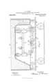
- FIG. 1 is a longitudinal section of the bathtub pattern provided with the fixtures;
- Fig. 2 is a cross section of the same on line 22 in Fig. 1;
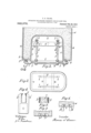
- Fig. 3 is a plan of the pattern;
- Fig. 4 is a side View of one of the forks carrying two prongs with loose tins thereon;
- Fig. 5 is a plan of such fork, and
- Fig. 6 illustrates the retraction of the said prongs from the sand.
- Fig. 7 is a section of the sand with recesses having rectangular undercut.
- a designates the metal flask with flange Z) around the bottom edge to support the sand w adjacent to the outer side of the bathtub pattern which has sides 0 and bottom (Z.
- the pattern and flask are shown supported by blocks A upon a truck B, thus leaving an open space beneath the bottom of the pattern-body. Into this open space, bearings c are projected from the opposite lower edges of the pattern, and an eccentric shaft 7 is journaled therein and formed with an eccentric portion g.
- Bars h are extended across the pattern, at a suitable distance below the bottom surface (Z of the pattern, in which the aper- Specification of Letters Patent.
- tures i are formed to project the lug-molding prongs 7'. Four pairs of such apertures are formed in the bottom of the pattern, to mold the lugs required for four feet.
- Two beams 71 are secured longitudinally upon the crossbars hand formed upon their opposite ends with guides 70 at right angles to the surface of the pattern and in a line with the center of each pair of apertures, and slides Z are fitted to such guides and connected at one end to the prongs in one pair of apertures.
- Each of the guides is formed, upon the same side of the slide, with a pivotbearing an, and a bell-crank n is pivoted thereon and one arm connected to the adj acent slide.
- a link 0 connects the two bellcranks under each of the beams 71?, and such link has a transverse slot 79 at the middle fitted to the eccentric portions 9 of the cocentric shaft
- a crank g is attached to the end of the shaft, and stops 7) are formed upon the pattern to restrict it to a movement of ninety degrees.
- Such movement indicated by the dotted arcg in Fig. 1, may turn the eccentric lengthwise of the link 0 or transversely thereto, and operates to move the slides a sufficient distance to project the prongs when in one position of the crank and to retract them in the other position.
- the turning of the eccentric shaft thus operates both the links and all four of the slides simultaneously.
- Fig. 1 the prongs are shown jointed by pivots r to a shank s which is secured movably upon the upper end of the slide by a set-screw t, thus permitting the prongs to project more or less in the same movement of the slide.
- the prongs are oppositely inclined toward one another and the apertures i made loose enough for them to move freely through the same, and their upper ends when projected into the molding sand form inclined lugs, which are indicated by the dotted lines a in Fig. 1, and produce the inclination of the lugs without the use of any tins or loose pieces upon the prongs.
- the shank s and the prongs may be termed a fork, and such fork may be made with rigid parallel prongs, as shown in Fig. 4, if it be desired to use beveled or rectangular tins in forming the lugs.
- the integral prongs are marked 7" in Fig. 4, and are shown in Fig. 4 provided with beveled tins o; and in Fig. 7 the sand 3 is shown with recesses having rectangular undercut 3 as when formed with rectangular tins.
- the portions of the eccentric shaft f which engage the slots 79 of the two links 0 operate as two independent eccentrics, and it is immaterial whether the shaft be made with one bent portion forming two eccentrics a;
- eccentric-shaft applies equally to both constructions.
Landscapes
- Engineering & Computer Science (AREA)
- Mechanical Engineering (AREA)
- Bathtub Accessories (AREA)
Description
2 SHEETS-SHEET 1.
Patented Feb. 22, 1910.
T. S. CRANE.
APPARATUS FOR MOLDING UNDERCUT LUGS 0N BATH .IUBS.
APPLICATION FILED OCT. 5, 1909.
@2223: g (A) v ANDREW a, GRAHAM co. FHOTO-LIIHOGRAPMERS,WASHNGTON. I:v c.
T. S. CRANE.
APPARATUS FOR MOLDING UNDEROUT LUGS ON BATH TUBS.
APPLICATION FILED OCT. 5, 1909.
Patented Feb. 22, 1910.
2 SHEETS-SHEET 2.
UNITED STATES PATENT CFFICE.
THOMAS S. CRANE, OF EAST ORANGE, NEW JERSEY, ASSIGNOR TO MoCRUlVI-HOWELL COMPANY, A CORPORATION OF CONNECTICUT.
APPARATUS FOR MOLDING UNDERCUT LUGS ON BATH-TUBS.
T 0 all whom it may concern:
Be it known that I, THOMAS S. CRANE, a citizen of the United States, residing at 3 University Place, East Orange, county of Essex, and State of New Jersey, have invented certain new and useful Improvements in Apparatus for Molding Undercut Lugs on Bath-Tubs, fully described and represented in the following specification and the accompanying drawings, forming a part of the same.
In the casting of metal bathtubs it is common to form undercut lugs or ribs in pairs upon the bottom of the bathtub between which ribs the shanks of the feet may be held.
The object of the present invention is to facilitate the molding of such undercut lugs, and the invention consists of slides mounted within the pattern to move at right angles to its surface and connected each with two prongs to mold one pair of the lugs, an eccentric shaft journaled upon the pattern and connections from such eccentric shaft to all of the slides, to move them simultaneously in retracting or projecting the prongs.
The invention will be understood by reference to the annexed drawing, in which- Figure 1 is a longitudinal section of the bathtub pattern provided with the fixtures; Fig. 2 is a cross section of the same on line 22 in Fig. 1; Fig. 3 is a plan of the pattern; Fig. 4: is a side View of one of the forks carrying two prongs with loose tins thereon; Fig. 5 is a plan of such fork, and Fig. 6 illustrates the retraction of the said prongs from the sand. Fig. 7 is a section of the sand with recesses having rectangular undercut.
a designates the metal flask with flange Z) around the bottom edge to support the sand w adjacent to the outer side of the bathtub pattern which has sides 0 and bottom (Z.
The pattern and flask are shown supported by blocks A upon a truck B, thus leaving an open space beneath the bottom of the pattern-body. Into this open space, bearings c are projected from the opposite lower edges of the pattern, and an eccentric shaft 7 is journaled therein and formed with an eccentric portion g.
Bars h are extended across the pattern, at a suitable distance below the bottom surface (Z of the pattern, in which the aper- Specification of Letters Patent.
Application filed October 5, 1909.
Patented Feb. 22, 1910.
Serial No. 521,091.
tures i are formed to project the lug-molding prongs 7'. Four pairs of such apertures are formed in the bottom of the pattern, to mold the lugs required for four feet.
Two beams 71; are secured longitudinally upon the crossbars hand formed upon their opposite ends with guides 70 at right angles to the surface of the pattern and in a line with the center of each pair of apertures, and slides Z are fitted to such guides and connected at one end to the prongs in one pair of apertures. Each of the guides is formed, upon the same side of the slide, with a pivotbearing an, and a bell-crank n is pivoted thereon and one arm connected to the adj acent slide. A link 0 connects the two bellcranks under each of the beams 71?, and such link has a transverse slot 79 at the middle fitted to the eccentric portions 9 of the cocentric shaft A crank g is attached to the end of the shaft, and stops 7) are formed upon the pattern to restrict it to a movement of ninety degrees. Such movement, indicated by the dotted arcg in Fig. 1, may turn the eccentric lengthwise of the link 0 or transversely thereto, and operates to move the slides a sufficient distance to project the prongs when in one position of the crank and to retract them in the other position. The turning of the eccentric shaft thus operates both the links and all four of the slides simultaneously.
In Fig. 1, the prongs are shown jointed by pivots r to a shank s which is secured movably upon the upper end of the slide by a set-screw t, thus permitting the prongs to project more or less in the same movement of the slide. The prongs are oppositely inclined toward one another and the apertures i made loose enough for them to move freely through the same, and their upper ends when projected into the molding sand form inclined lugs, which are indicated by the dotted lines a in Fig. 1, and produce the inclination of the lugs without the use of any tins or loose pieces upon the prongs. The shank s and the prongs may be termed a fork, and such fork may be made with rigid parallel prongs, as shown in Fig. 4, if it be desired to use beveled or rectangular tins in forming the lugs. The integral prongs are marked 7" in Fig. 4, and are shown in Fig. 4 provided with beveled tins o; and in Fig. 7 the sand 3 is shown with recesses having rectangular undercut 3 as when formed with rectangular tins.
The operation of the slides and their reciprocating mechanism is the same whatever form of fork or prongs be used.
The portions of the eccentric shaft f which engage the slots 79 of the two links 0 operate as two independent eccentrics, and it is immaterial whether the shaft be made with one bent portion forming two eccentrics a;
operate the links 0, as shown in the drawing, or be made straight as is common in such cases, and the eccentrics made larger than the shaft at two different points.
The term eccentric-shaft applies equally to both constructions.
Having thus set forth the nature of the invention what is claimed herein is:
l. The combination, with a bathtub pattern, of two apertures through the surface of the pattern near each of its opposite ends at the location of the desired lugs, prongs projected through each pair of the apertures, guides within the pattern at right angles to the apertured surface and slides fitted to the same and engaged each with one pair of the prongs, an eccentric shaft journaled upon the pattern, and bell-cranks and connections from such eccentric shaft to the two slides for projecting or retracting the four prongs simultaneously.
2. The combination, with a bathtub pattern, of two apertures through the surface of the pattern near each of its opposite ends at the location of the desired lugs, prongs projected through each pair of the apertures, two slides at right angles to the surface of the pattern connected each to one pair of the prongs, two crossbars extended across the pattern, a beam attached to such crossbars and provided at the ends with guides for the two slides, an eccentric shaft journaled upon the pattern, and bell-cranks and connections from such eccentric shaft to the two slides for retracting them simultaneously.
3. The combination, with a bathtub pattern, of two apertures through the surface of the pattern near each of its opposite ends at the location of the desired lugs, prongs projected through each pair of the apertures, two slides supported within the pattern at right angles to its surface, and engaged each to one pair of the prongs, .a beam supported longitudinally within the pattern with guides at its opposite ends for the said slides, and
slides, and an eccentric shaft ournaled upon the pattern and connected to the two bellcranks for retracting the slides simulta neously.
4. The combination, with a bathtub pattern, of four apertures through the surface of the pattern near each end of the same at the location desired for the lugs, inclined prongs projected at opposite inclinations through each pair of the apertures, four slides at right angles to the surface of the pattern jointed to the pairs of inclined prongs, crossbars within the pattern, two beams supported longitudinally upon such crossbars having a guide at each of its ends fitted to one of the slides, a shaft j ournaled upon the pattern with eccentric thereon, and connections from the eccentric to the four slides for retracting them simultaneously.
5. The combination, with a bathtub pattern, of four apertures through the surface of the pattern near each end of the same at the location desired for the lugs, two inclined prongs projected at opposite inclinations through each pair of the apertures, four slides at right angles to the surface of the pattern jointed to the pairs of inclined prongs, crossbars within the pattern and two beams supported longitudinally upon such crossbars having a guide at each of its ends fitted to one of the slides, bearings upon the bottom of the pattern at opposite sides, an eccentric shaft extended across the same with handle for oscillating it, the shaft having an eccentric portion, bell-cranks pivoted adjacent to the bottoms of the four slides, and two links connecting the bell-cranks in pairs and connected also with the eccentric portion of the shaft, and operating to retract all the slides when the shaft is oscillated.
6. The combination, with a bathtub pattern, of two apertures through the surface of the pattern near its opposite ends at the location of the desired lugs, forks having each a pair of prongs projected through each pair of the apertures, guides within the pattern at right angles to the apertured surface, slides fitted to the said guides and connected adjustably to the said forks, and means for reciprocating the slides simultaneously during the molding operation.
In testimony whereof I have hereunto set my hand in the presence of two subscribing J. VALTER GREENBAUM.
Priority Applications (1)
| Application Number | Priority Date | Filing Date | Title |
|---|---|---|---|
| US52109109A US949976A (en) | 1909-10-05 | 1909-10-05 | Apparatus for molding undercut lugs on bath-tubs. |
Applications Claiming Priority (1)
| Application Number | Priority Date | Filing Date | Title |
|---|---|---|---|
| US52109109A US949976A (en) | 1909-10-05 | 1909-10-05 | Apparatus for molding undercut lugs on bath-tubs. |
Publications (1)
| Publication Number | Publication Date |
|---|---|
| US949976A true US949976A (en) | 1910-02-22 |
Family
ID=3018390
Family Applications (1)
| Application Number | Title | Priority Date | Filing Date |
|---|---|---|---|
| US52109109A Expired - Lifetime US949976A (en) | 1909-10-05 | 1909-10-05 | Apparatus for molding undercut lugs on bath-tubs. |
Country Status (1)
| Country | Link |
|---|---|
| US (1) | US949976A (en) |
-
1909
- 1909-10-05 US US52109109A patent/US949976A/en not_active Expired - Lifetime
Similar Documents
| Publication | Publication Date | Title |
|---|---|---|
| US784781A (en) | Combined ironing-board and table. | |
| US949977A (en) | Bath-tub-molding apparatus. | |
| US962192A (en) | Adjustable concave. | |
| US173062A (en) | William | |
| US1487196A (en) | Material-handling device | |
| US1333971A (en) | Molding-flask | |
| US516610A (en) | Charles f | |
| US1071445A (en) | Buttonhole measuring and cutting machine. | |
| US943052A (en) | Coupling. | |
| US823871A (en) | Apparatus for cutting girders. | |
| US821642A (en) | Concrete-block machine. | |
| US971907A (en) | Molding apparatus. | |
| US782081A (en) | Planer-tool. | |
| US715288A (en) | Device for cutting glass. | |
| US746800A (en) | Shears for bars of structural shapes. | |
| US957308A (en) | Wagon-jack. | |
| US690074A (en) | Clamping mechanism. | |
| US1233075A (en) | Safety-jack. | |
| US118303A (en) | Improvement in lap-boards | |
| US558121A (en) | Trestle-liner or power-jack | |
| CN309550058S (en) | Shaver (TD6019) | |
| US417237A (en) | Plate-glass carrier | |
| US1204581A (en) | Molding-machine. | |
| US1033050A (en) | Combined arbor-press and punching-machine. | |
| US283905A (en) | latshaw |